Week 6 - CHT Analysis on a Graphics card
Aim
Perform Conjugate Heat Transfer (CHT) simulation on a real-like graphic card model kept in the way of air with inlet velocity renging from 1m/s to 5m/s.
Introduction
Conjugate heat transfer is a type of heat transfer analysis between solids and fluid(s). This type of heat transfer includes both convection (between fluids) and conductive (between solids) heat transfer, and could be both forced and by natural convection.
Graphic card is an electronic device comprises of many parts to work together to serve the purpose of processing input and giving the best expected output. A processor is the main component of it and creates the most heat which needs to be dissipiated into envirenment for the optimal working of the system.
The heat dissipiation is done with the help of fins present on it's top increasing the surface area for interaction with free air.
Solving & Modelling approach
I have soved through the stages mentioned above with the help of videos shown and guidance of the technical staff.
The process fluesnt fluid flow will be done in following these 5 steps:-
1) Geometry - The geometry of the model will be formed where the actual flow will flow/interfere
2)Mesh - The meshing of the volume is done whoose parameters are set by default with help of 'Boundary Box'
3)Setup - The initial and boundary conditions or parameters and the model choosen are given to the model.
4) Solutions - Based on conditions and requirements the result is calculated with the help of model choosen
5) Results - The final results are appeared here from where the investigation of simulation is done.
| Pre-processing and solver setting |
Step 0) Download and import the model
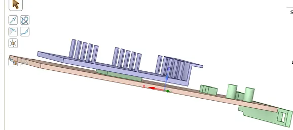
Step 1) Prepare the geometry of model
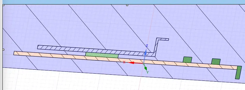
1.1) Share the topo of the model
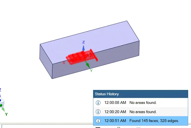

Step 2) mesh the system
2.1) Assign names to the components
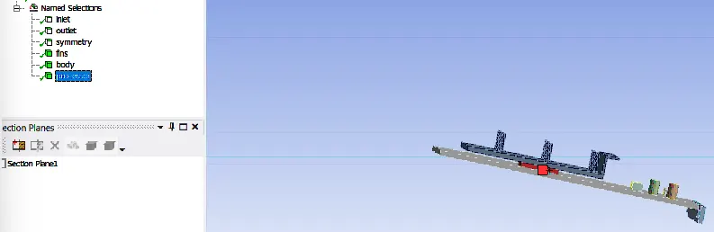
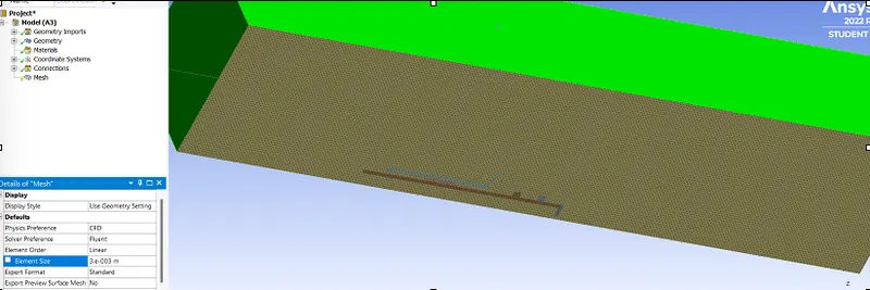
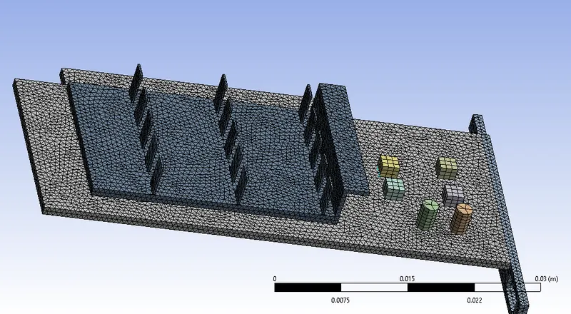
2.2) Give element size to enclosure and graphic card components.
Enclosure = 3mm
Graphic card = 0.5mm

2.3) Give sizing to the mesh
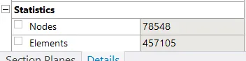
Base condition
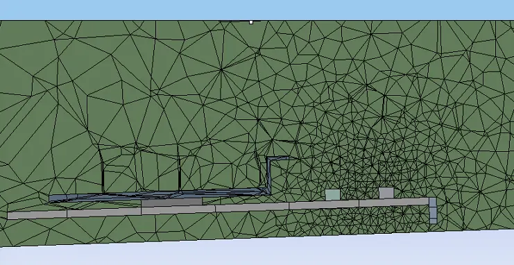
Refined Condition
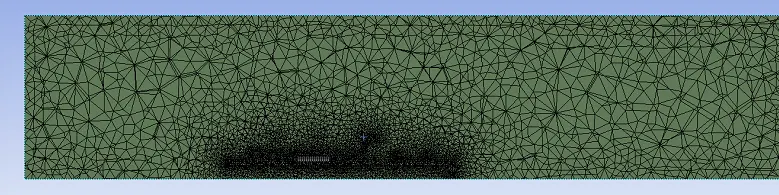
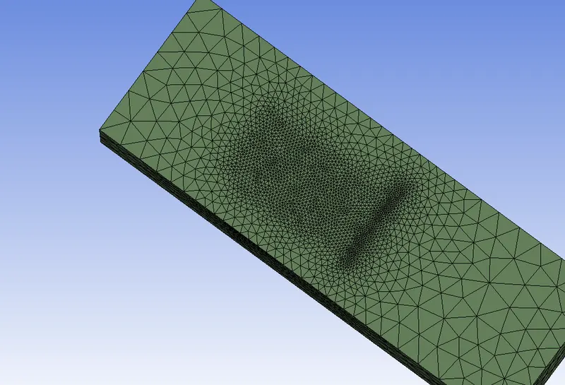
Step 3) Setup the system's conditions and parameters
3.1) Set the physics as mentioned below
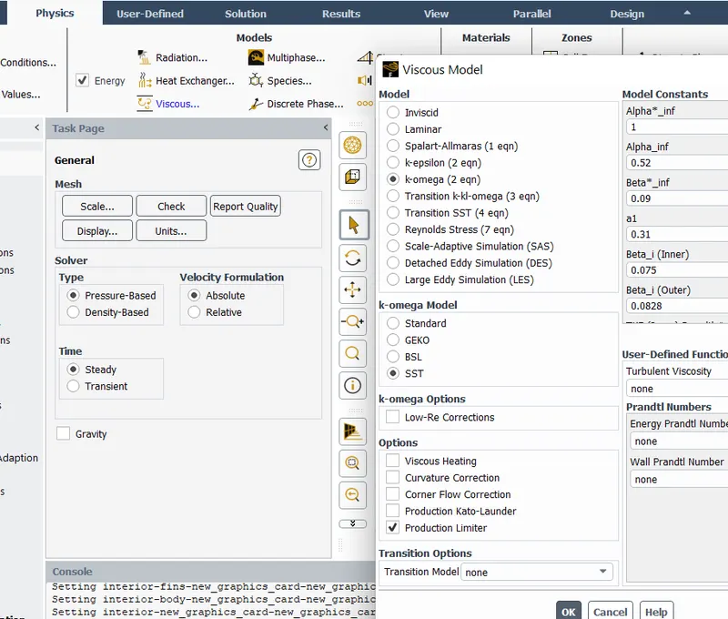
3.2) Create solid materials for graphic component components
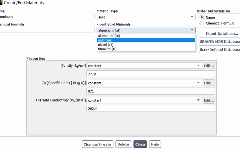
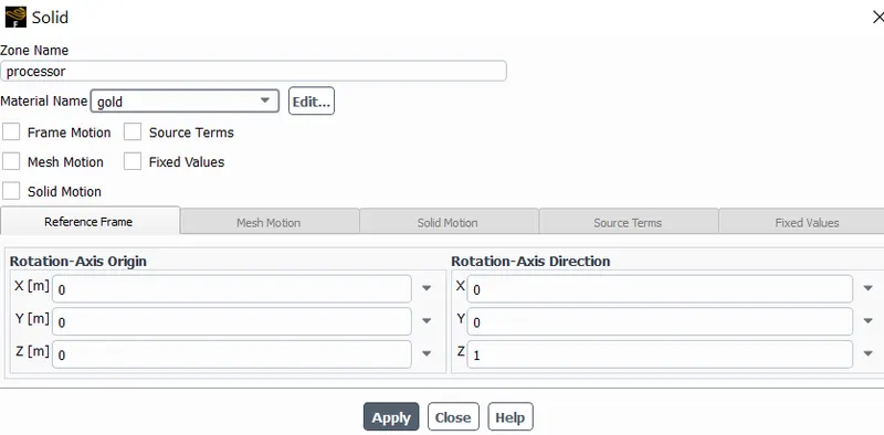
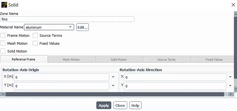
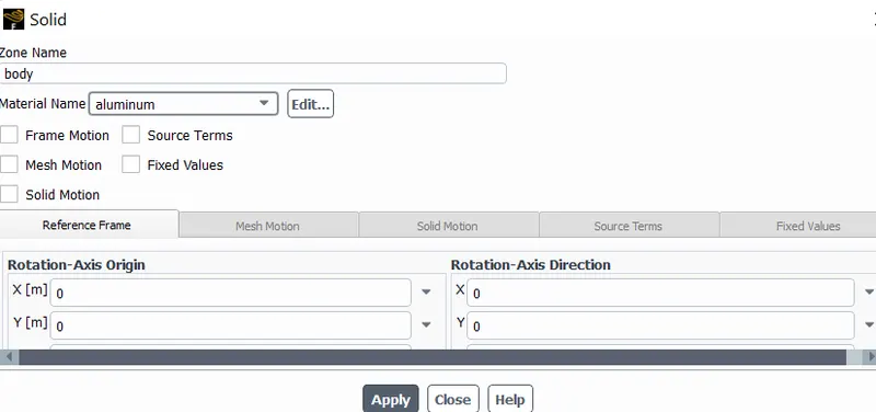
3.3) Assign material to solid components from cell zones
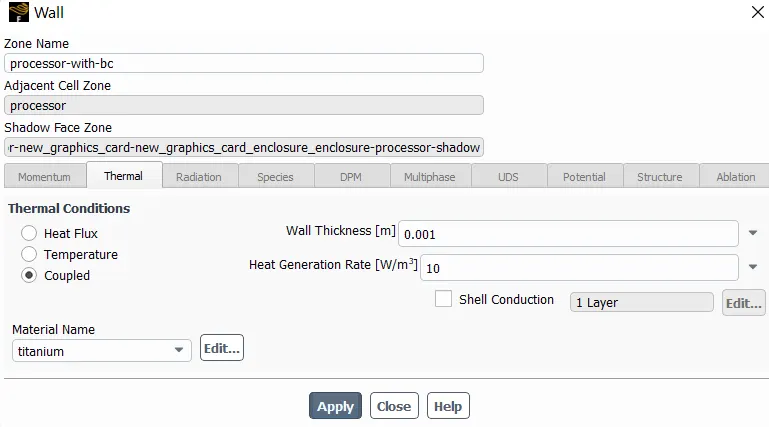
3.4) Give boundary conditions
3.5) Standard initialise the system
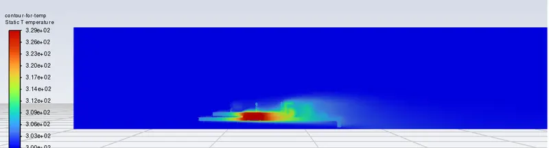
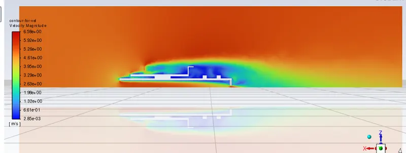
3.6) Create plane and contour for velocity and temperature of system.
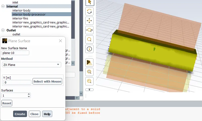
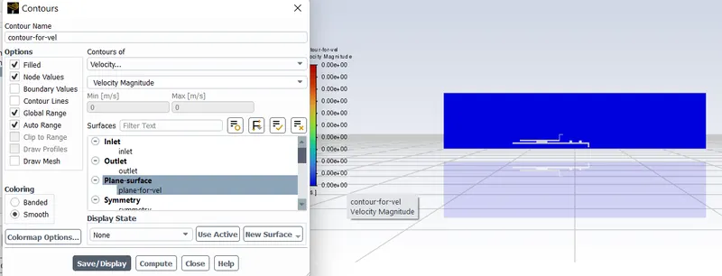
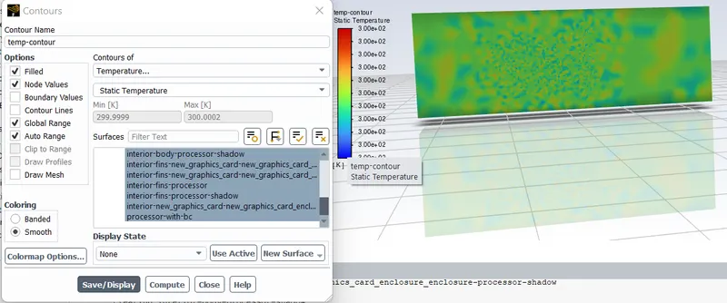
3.7) Provide setup of animation to the system
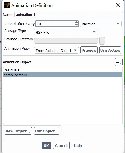
3.8) Calculate the result.
Time Step = 0.01s
No. of Iteration = 250
Step 4) Manupilate the result appearance as per our convinience
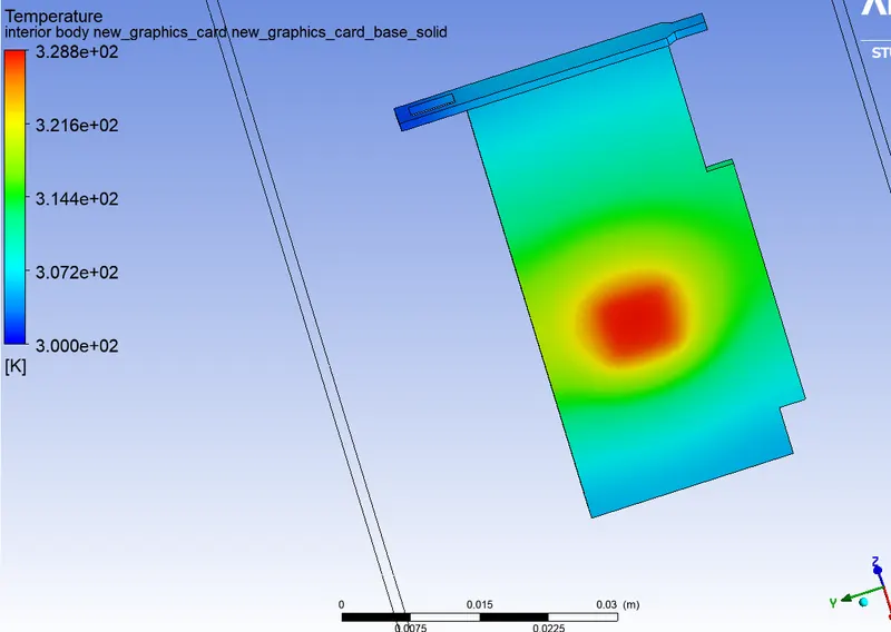
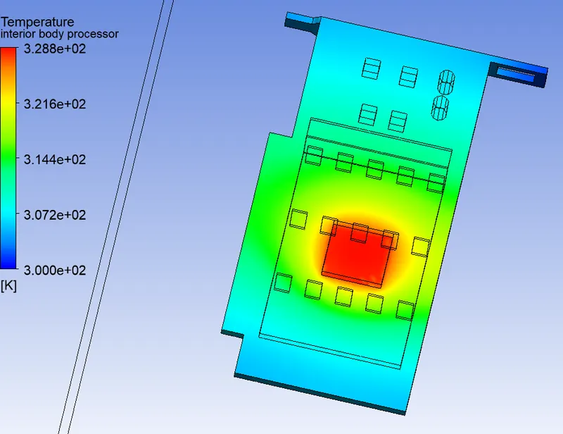
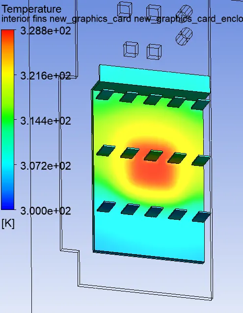
4.1) Show only the graphic card parts and give them variable color settings with temperature as variable
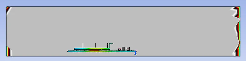
4.2) Insert a plane in XZ plane name it 'Mid-plane'
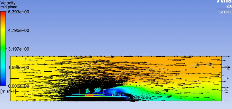
4.3) Under color give it the velocity dependent color and heat transfer co-efficient dependent color with vector representation to it.

Result
The simulation gives the following results:-
1. Velocity Contour
2. Temperature contour
3. Temperature in model
4. Velocity vector plane appearance
5. Heat transfer coefficient
Conclusion
The following points can be concluded from this simulation:-
1. The cooling effent increases with increase in air velocity
2. System gives more acuraate results for smaller element size
3. The potential hotspot region is identified near the processor region.
4. From vector representation ,we can noteice the presence of recirculation region.
Glink for animation
https://drive.google.com/file/d/1CPGTb5ar4TPuCmRXq4gP7K6_T3b2E4b1/view?usp=sharing