Week 6 - CHT Analysis on a Graphics card
Aim : To simulate steady state Conjugate Heat Transfer (CHT) analysis on a 3-d model of graphics card and run simulations with different inlet velocities and discuss the result.
Objective :
- Run the simulation by varying the velocity from 1m/sec to 5m/sec for at least 3 velocities and discuss the results.
- Find out the maximum temperature and heat transfer coefficient attained by the processor.
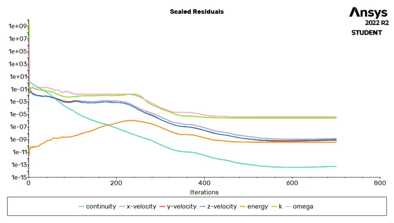
- Prove that the simulation has achieved convergence with appropriate images and plots.
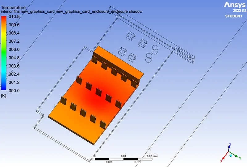
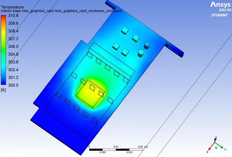
- Identify potential hotspots on the model
Theory : 1. Conjugate Heat Transfer
Conjugate Heat Transfer is defines as the heat transfer between two domains by exchange of thermal energy.For a system the thermal energy available is defined by its temperature and the movement of thermal energy is defined by its heat flux through the walls.There are 3 modes of Heat Transfer they are Conduction,Convection and Radiation. Heat transfer in solid happens due to conduction process, where the heat transfer in fluid happens through convection process.
CHT provides the temperature prediction and the hotspot regions at the solid-liquid interface and also we can also predict the heat transfer accurately. It also provides the velocity and pressure distribution of fluid moving inside the solid. We can also use the CHT in design optimization for improvement for heat transfer and cooling capacity.
2. Graphic Card :
A graphic card is a type of display adapter or video card installed within most computing devices to display the graphical data with high clarity,colour definaition and overall appearance. A graphic card provides high quality visual display by processing and executing graphical data using advanced graphical techniques,features and function.
A graphic card is primarily designed to remove the graphical processing task from the processor or RAM. It includes a dedicated graphical processing unit (GPU) and a dedicated RAM that help it to process graphical data quickly. Graphic card also has a dedicated heat sink to keep the heat out of the GPU.
Procedure :1. Spaceclaim Geometry
Download the geometry of the graphic card from the given link.
The geometry of the graphic card is already enclosed in a enclosure we have to make sure that the geometry is shared otherwise we will not have a conformal mesh and the information will not be shared. So do make the topology shared to do :
Workbench> Share > select the body > share > Ok.
The parts of the graphic card is shown below :
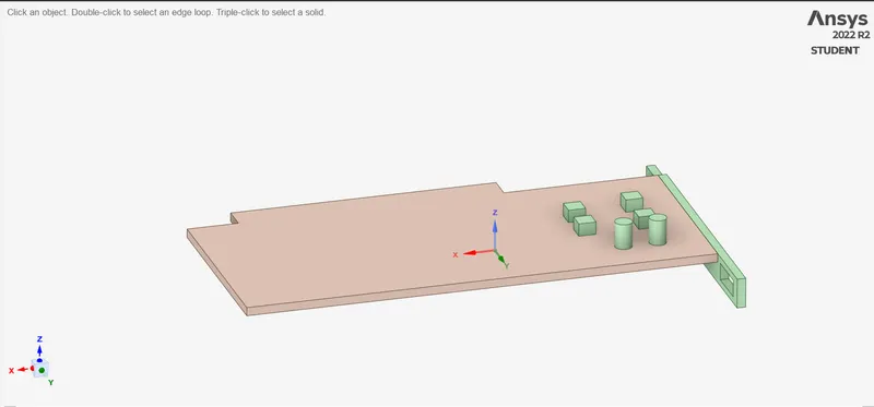 Base of the graphic card
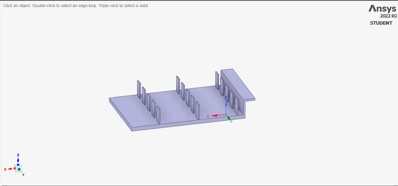 Fins or the sink of the graphic card
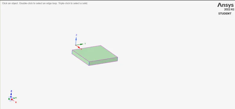 Processor
The whole graphic card will look like this
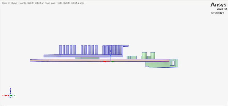 the heat sink is sitauted over the graphic card all the heat generated from the processor will be conducted to the Fins and the inlet velocity will convect the heat from the sink to outlet.
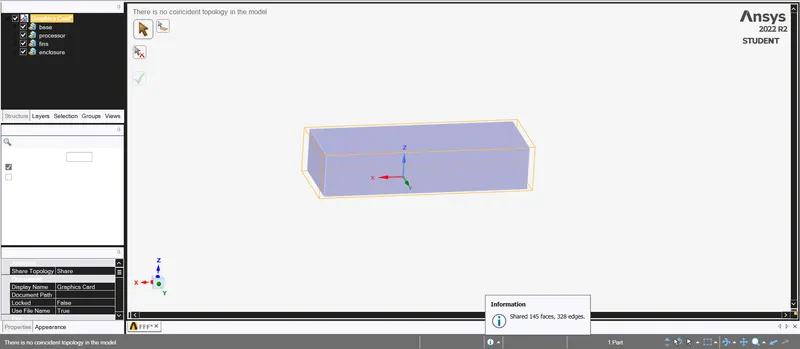 the topology is shared and we can move on to the meshing of the geometry.
2. Meshing
First we will provide names to the geometry, the name selections are
Processor
Base
Fins
Four side symmetry walls and inlet and outlet.
We will run two different meshes for the challange, first will be the coarse mesh and other will be the refined mesh.
(a). Default mesh:
Mesh size = 5.0mm
Number of elements = 97624
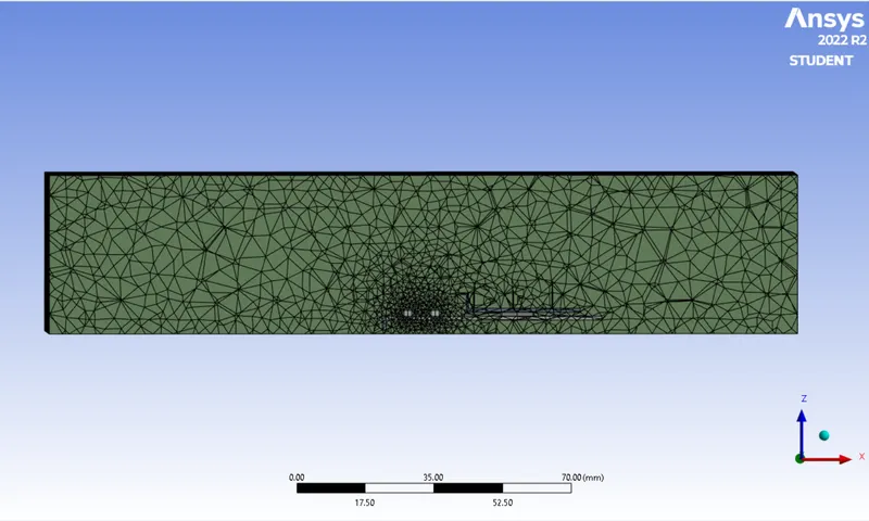
(b) Refined Mesh :To refine the mesh we will use the Body sizing option and mesh the named selection parts the main corncern of the simulation is is the heat transfer from the the fins and the processor so the mesh size will be fine over these parts.
mesh size ;
for Base plate = 1mm
Processor = 0.8mm
Fins = 0.8mm
Enclosure = 2 mm
No. of elemnts = 340352
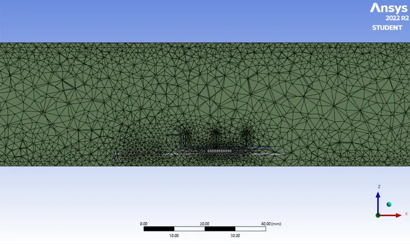
3. Fluent Setup :
Solver type : Pressure based
Steady state solver
Check the Energy equation
Turblent Model : K-Omega SST Model
Material for the parts of the graphic card
Base : FR-4 : density = 1850kg/m^3 , Cp = 1300J/kg k , k = 0.27
Fins : Aluminium : density = 2719kg/m^3 , Cp = 871J/kg k , k = 202.4
Processor : Silicon : density = 2330kg/m^3 , Cp = 710J/kg k , k = 148
Boundary Condition :
Inlet Velocity = 1, 3 and 5 m/s
Initial temperature = 300k
Cell zone conditions :
set Processor / core as source term as heat is generated by it in the graphic card.
Consider ,
Power supplied to Core (P) = 1W
We have,
Volume of processor (V) = 64 mm^3 = 64e-9 m^3
Therefore , Heat generated = P/V = 15625000 W/m^3
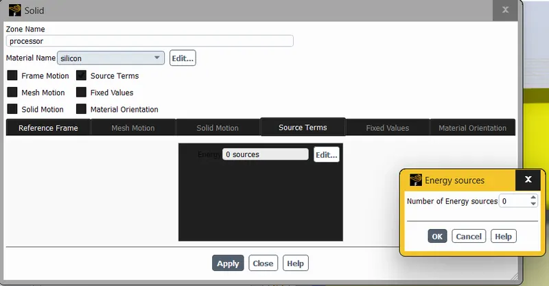
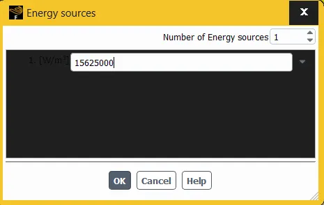
Assign the cell zones properly for solids to solids and fluid to fluid.
Refernce Value to calculate the temperature and the heat transfer coefficient at the processor
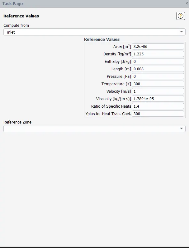
Results :
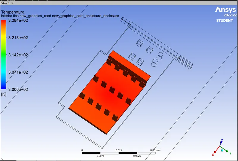
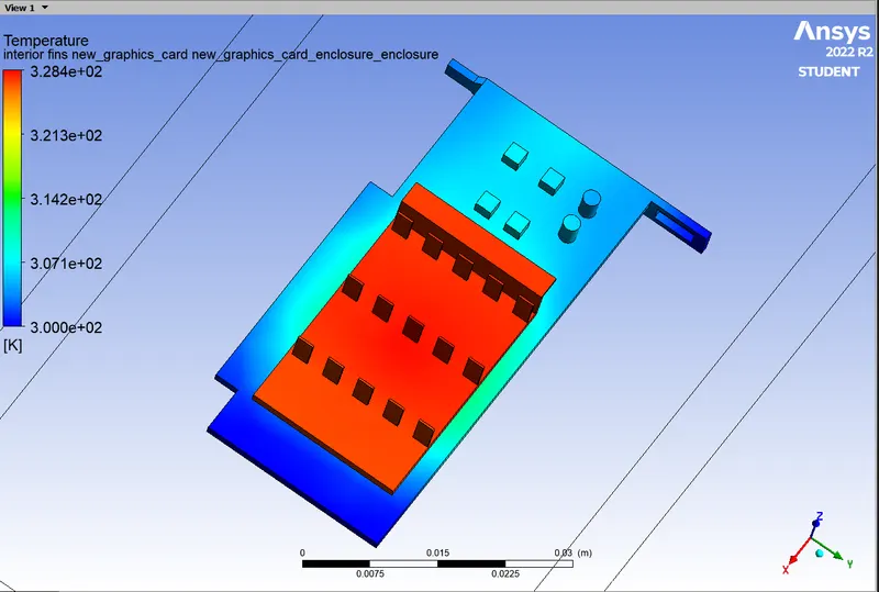
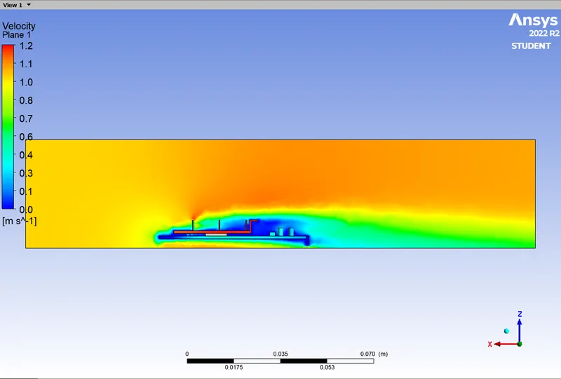
For Inlet velocity of 1m/s
Global Hotspot
Velocity contour
(2) for Inlet velocity of 3m/s
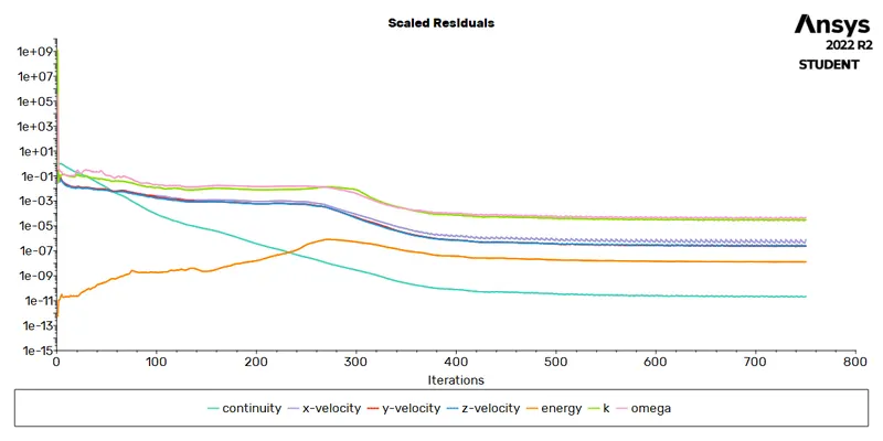
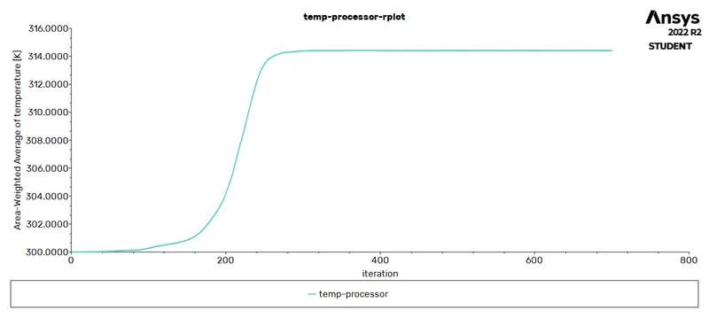
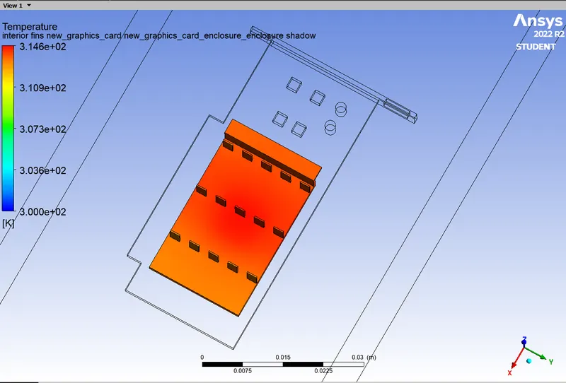
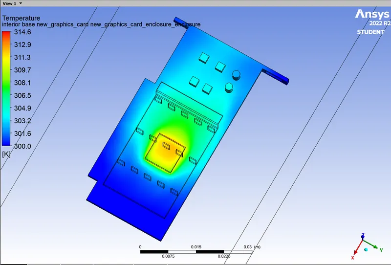
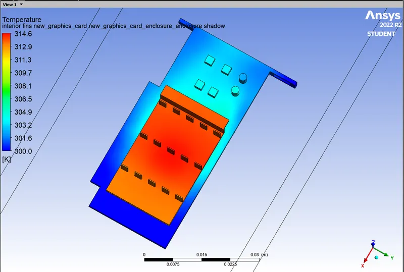
Global Hotspot
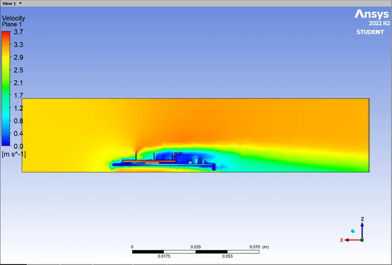 Velocity profile
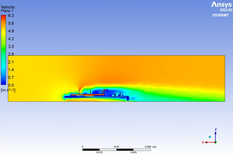
(c) for Inlet velocity of 5m/s
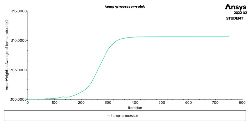
Global Hotspots
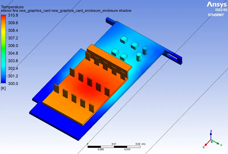
Velocity contour
Inlet Velocities Temperature at processor HTC at processor
(m/s) K (W/mk)
1 328.42 -6.06
3 314.41 -13.61
5 310.64 -19.17
Conclusion : 1. As the mesh gets refined the accuracy of the result increases and we get a more accurate result of heat transfer coefficient.
2. From the obtained results we can say that the values of the temperature at the processor decreases as the inlet velocity increases as mentioned in the above table.Hence it can be say that at higher inlet velocity results better cooling.
3. Furthermore, the temperature values at the fins when calculated we see drop of temperature values at fins getting low too.
4. The value of the Heat Transfer Coefficient at the processor gets increasing that shows that more heat gets transfferd at the outlet as the inlet velocity increases and that increses the component life and and keep the processor cool.