Week 6 - CHT Analysis on a Graphics card
Aim :
- to Perform a steady-state conjugate heat transfer analysis on a model of a graphics card.
- to use appropriate materials of your choice for the simulation. Make sure to properly define the correct solid and fluid zones.
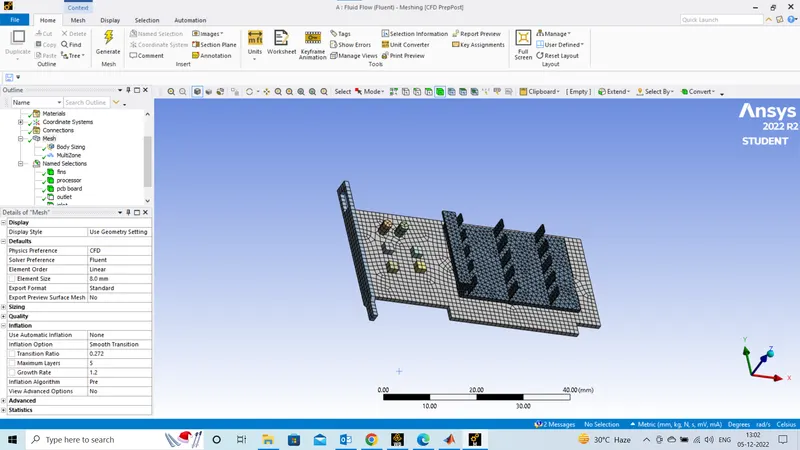
- toRun the simulation for best possible mesh with combination of coarse and refined mesh in different regions. Explain the reason for choosing the particular mesh settings.
Objectives:
- Run the simulation by varying the velocity from 1m/sec to 5m/sec for at least 3 velocities and discuss the results.
- Find out the maximum temperature and heat transfer coefficient attained by the processor.
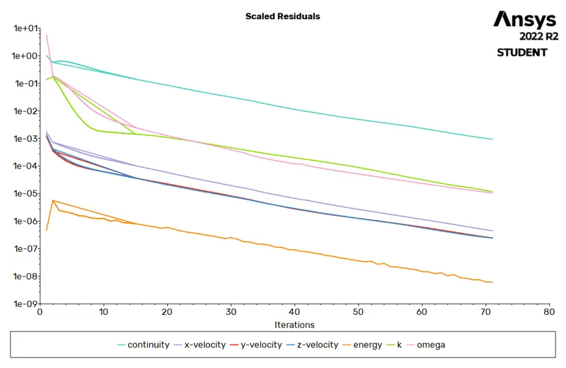
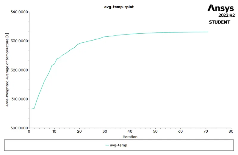
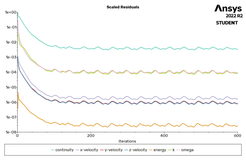
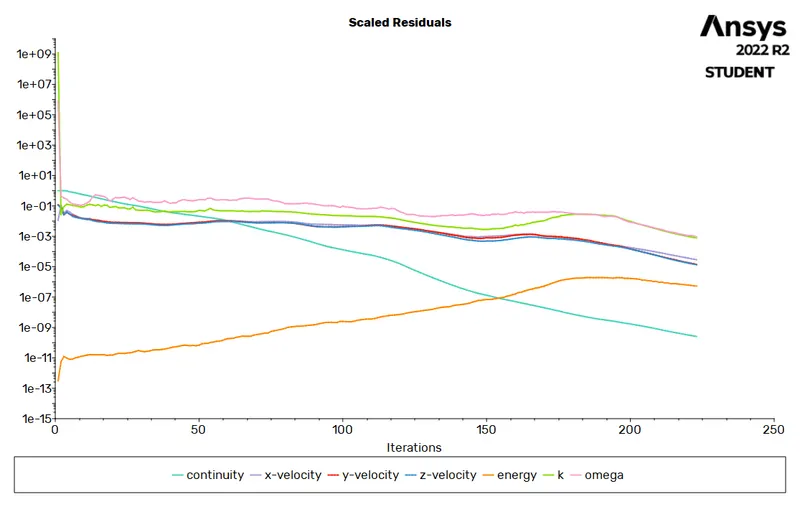
- Prove that the simulation has achieved convergence with appropriate images and plots.
- Identify potential hotspots on the model.
I. Introduction :
In this project, A steady state conjugate heat transfer analysis on a Graphic card model is done. Graphic card has become an everyday used object and a very importat part of any computer system, laptops etc. This product is mass produced daily in millions and has made computers exceptionally efficient. As they consume electricity to operate and running a heavy software or graphically challenging task on computer takes a toll on its graphics card, because of which it generates a large amount of heat. There is a limit to which any system can entertain heat to keep its parts under safe operating condition. We cannot go past these limits as it will damage the system, Cause failure of the product & system etc. But what we can do is find measures to cool this system, cool the graphic card so the system keeps running at optimum speed & condition.
There are various methods of cooling electrical components, through fan, thermal pastes / gels, double fanning, using materials that help dissipating the heat in the fans direction, arrangements of components etc. We have a graphic card model here which we will simulate in ansys fluent by applying heat on the processor/gpu of the graphic card while its contained in an enclosure. The air is passed at a certain velocity through the enclosure and we observe the heat dissipation through the fins by conduction from the processor, then observe how the flowing air cools the fin & observe the heat transfer taking place through it.
II. Parts & Materials of Graphic card :
There are many parts in a graphic card namely, Gpu/processor, fins, heat sinks, pcbs, connecting copper coiled wires, memory modules,pci connection port, connector pins etc.
The model used here is simplified to 3-4 important parts and isnt heavily detailed to save computational time & prove the point through analysis.
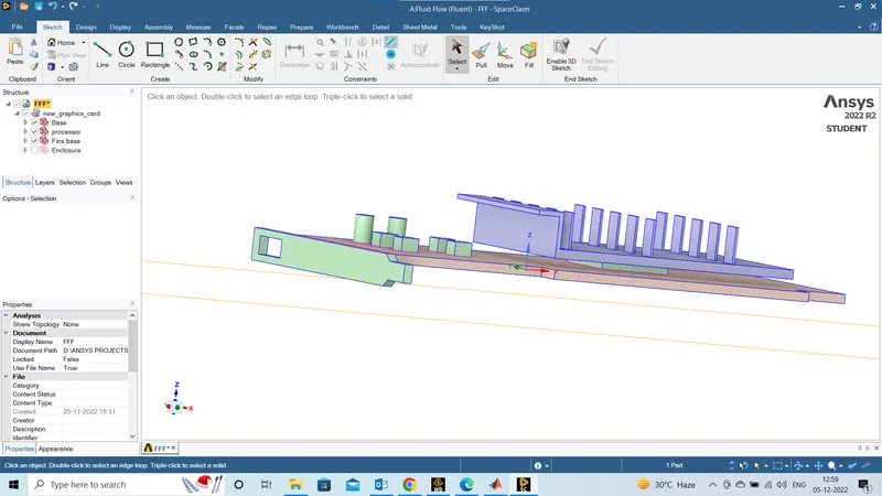
The parts of simplified model are - Processor, Fin & base. small memory modules are attached in as base.
Materials Considered for the analysis .
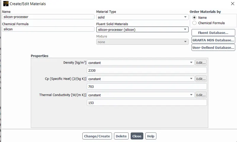
For processor - Silicon is choosen for this. Silicon is not the only material of the processor, its a very complex part made of mixtures of materials, for convenience, knowing silicon forms one of the major part of it its choosen.
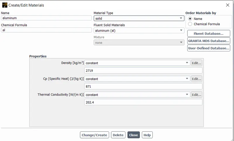
Fin - Aluminium .
processor -Silicon
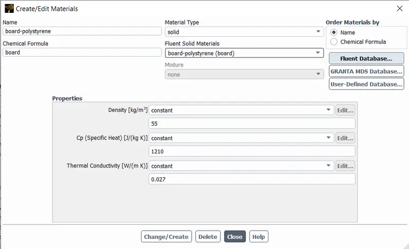
board - polystyrene
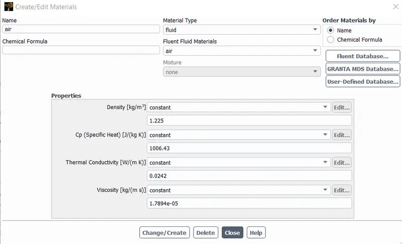
Fluid - air
Geometry :
Meshing :
Case Setup :
1. Pressure Based Solver.
2. Energy eqn on
3. Viscous model - k eps 2 eqn.
4. Time : Steady
5. Cell zone - Material set.
6. B.C -
Case 1 - inlet : 1m/s
Case 2- inlet : 3 m/s
Case 3- inlet : 5 m/s
Case 4 - inlet : 5m/s [Refined]
Inlet & outlet temp : 293.15 k
Pressure outlet 0 pascal.
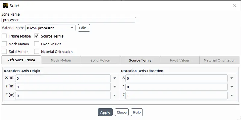
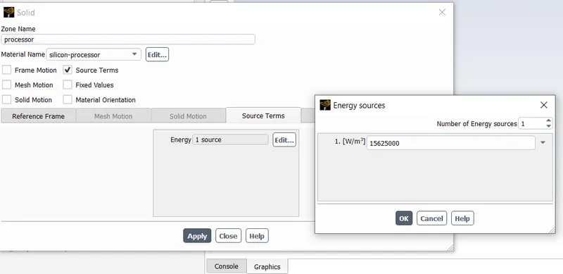
7. Source Term in Processor : 15625000 w/m^3.
To consider for heat generation in the processor many standard values were referred to from the internet & catelogues of Graphic card manufacturing companies like Nvidia. The power consumption lies anywhere between 40 to 120 watts from low end to high. However our gpu model's size is a little smaller than standard ( refer in the reference) . So the power Consumption considered is 9.9 watts.
The volume of model processor is 64 mm^3.
Hence calculating the Source Term as such :
Source Term = 9.964⋅10−9=154687500Wm39.964⋅10-9=154687500Wm3
Fluent setup :
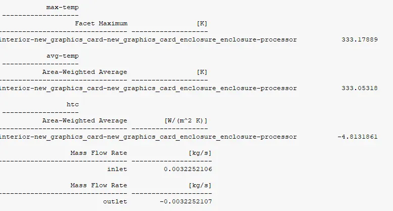
(velocity=1)
Avg temp:
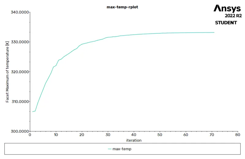
Max temp :
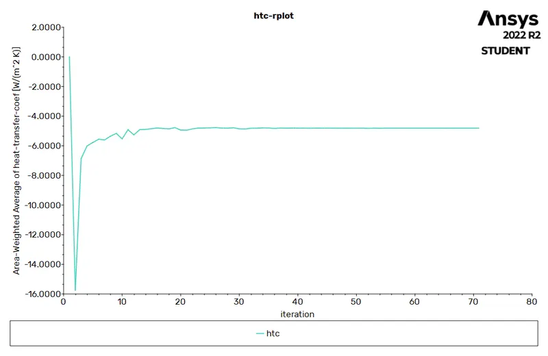
Heat transfer coefficient :
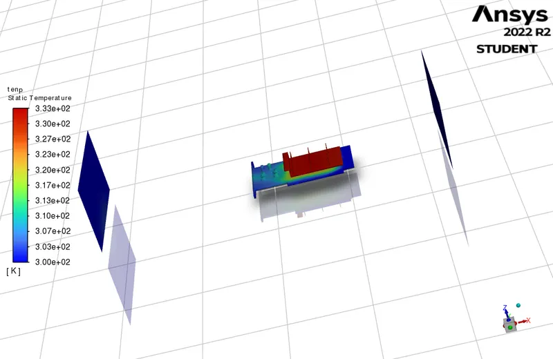
Temperature coontour :
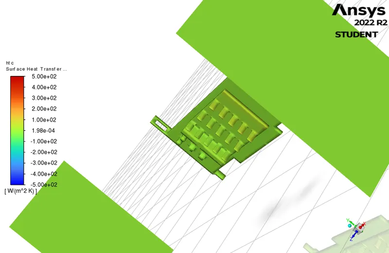
Heat tranfer coefficient contour :
Fluent setup :
velocity = 3m/s
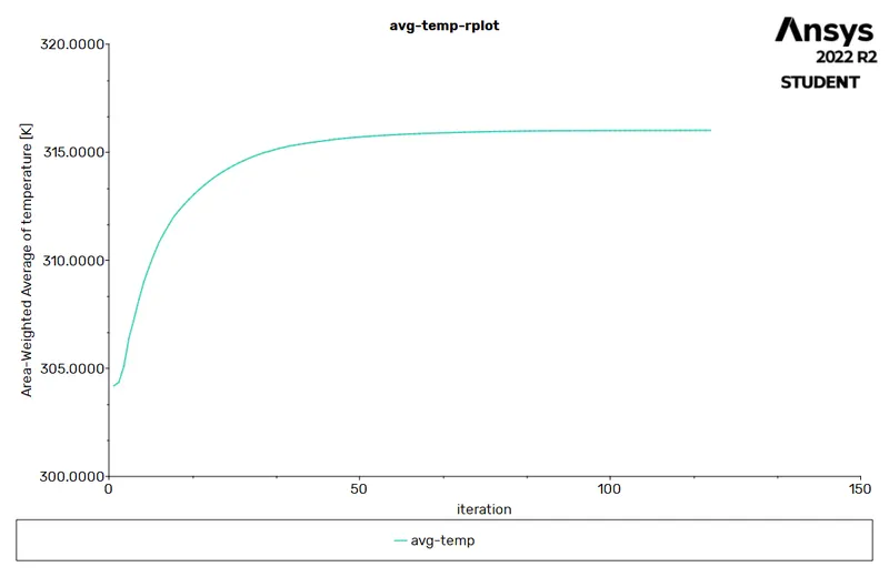
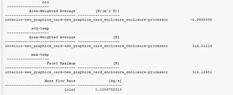
avg temp
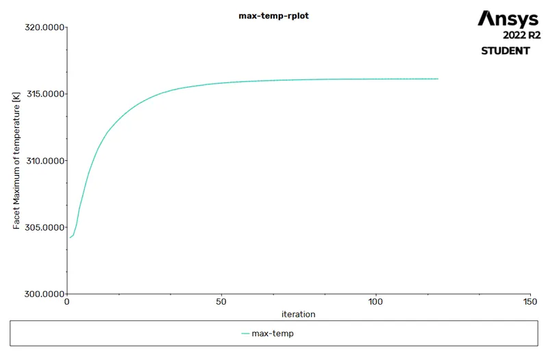
max temp :
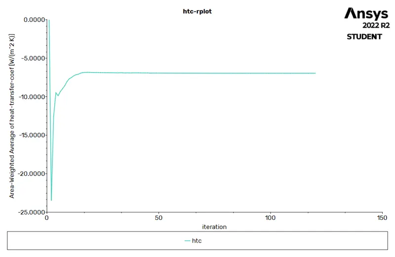
Htc :
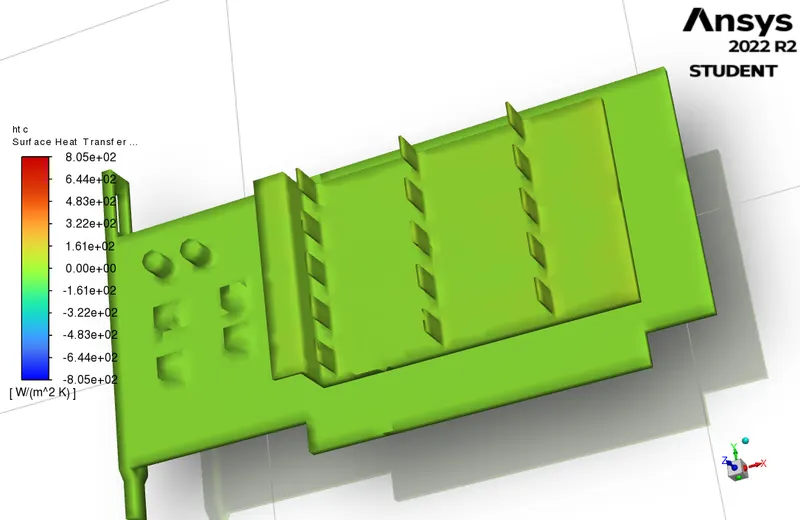
htc contour :
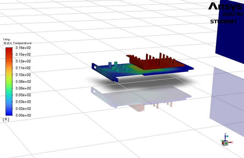
temp contour :
values :
Fluent setup :
Velocity - 5 m/s
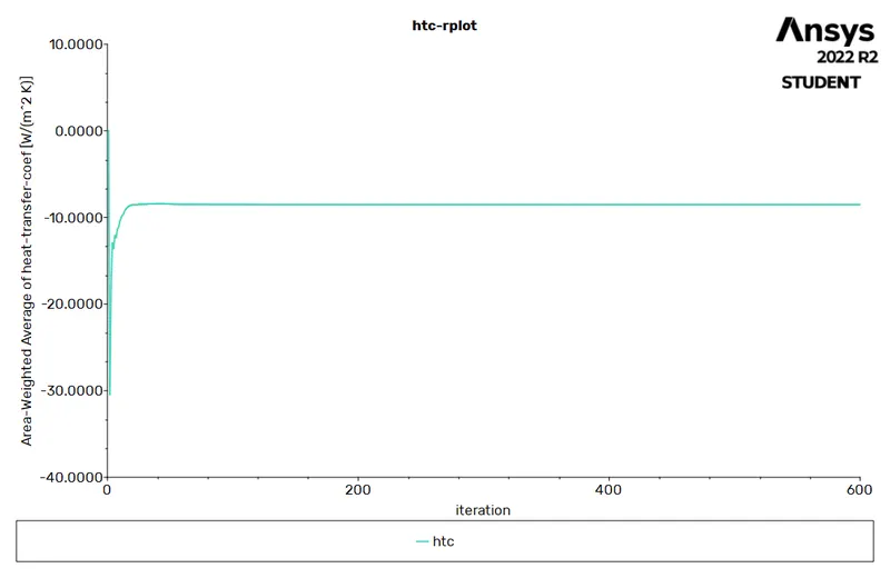
htc plot :
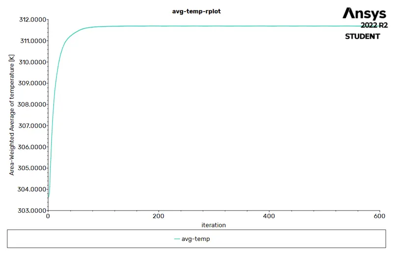
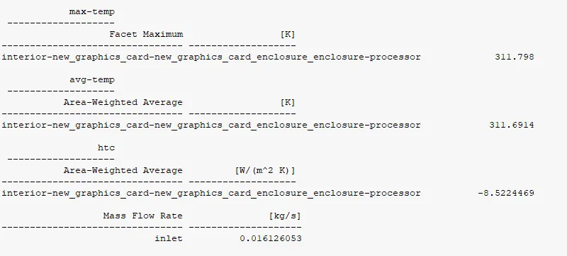
Avg temp :
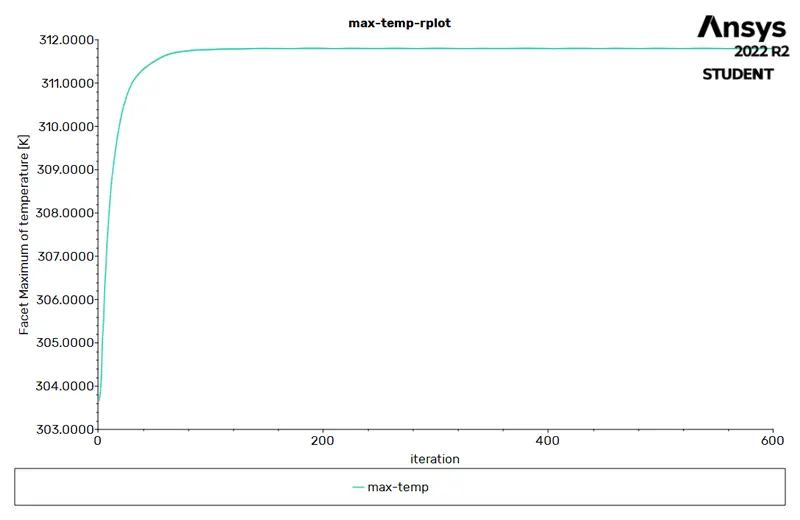
Max temp :
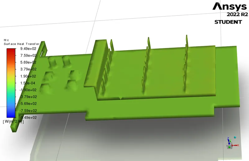
Htc contour :
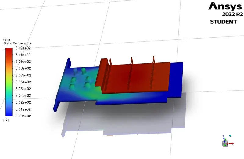
Temp contour :
Values :
fluent setup :
velocity - 5m/s(refined mesh )
Avg temp :
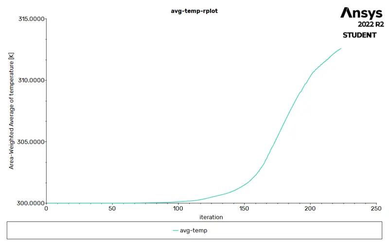
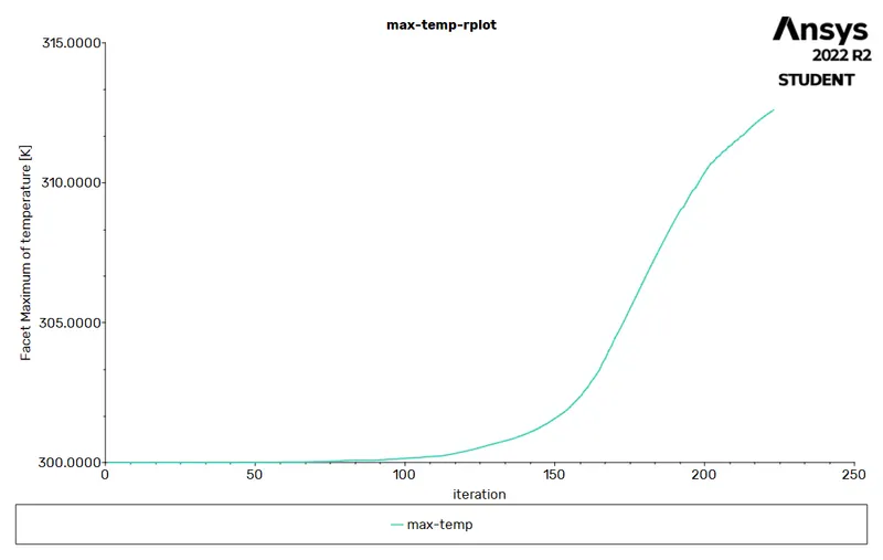
max temp :
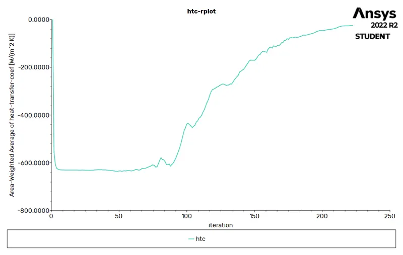
HTC :
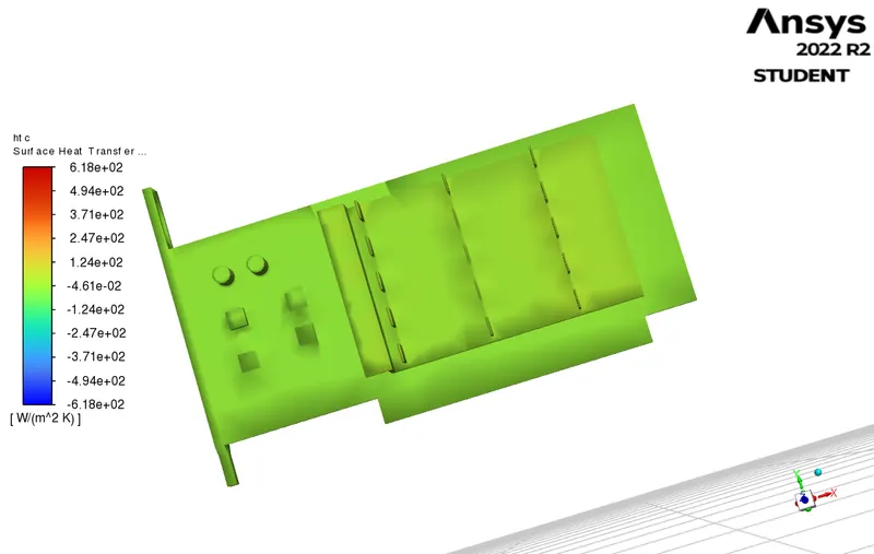
HTC CONTOUR :
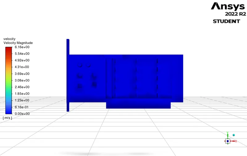
Velocity magnitude :
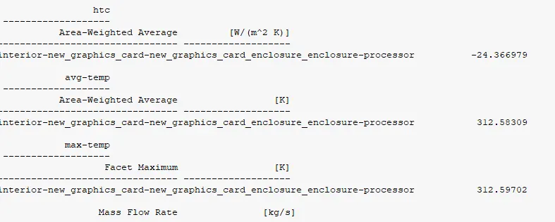
Values :
Cell zone and Material property conditions :
Difference :
| max temperature | avg temperature | HTC |
| v=1 m/s | 333.17 | 333.05 | -4.81 |
| v=3m/s | 316.011 | 316.12 | -6.9598 |
| v=5m/s | 311.6914 | 311.768 | -8.522 |
| v=5 m/s refined | 312 | 312 | -24 |
XI. Conclusions :
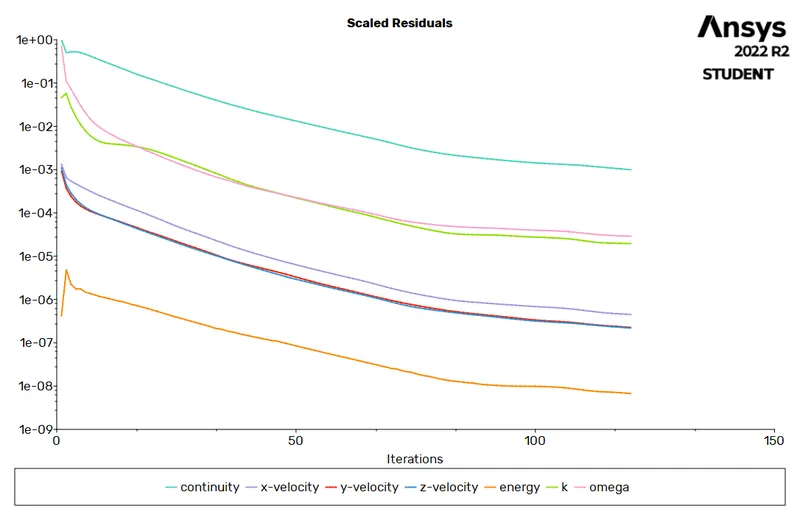
1. We conclude the solution convergence by first observing the residuals where all the equations converged . Secondly the desired results where achieved as we expected it. i.e the idea in mind of what the cht simulation results would prove was infact observed in every iteration of the solution which leads us to conclude a fully converged solution.
2. The max temperature attained by the processor will always vary, like it increased when the air flow was less and decreased when it was more. hence proper cooling of such electronic devices is necessary for efficient functioning.
3. The conjugate heat transfer study allowed us to peak into electronics heat distribution, working and many conceptual clearance which are before theoretically verified in hand calculations or text book principals.
4. Heat transfer coefficient is something which changes with materials used, hence engineers are very picky about the materials used in these cards as they are so compact, the need to provide higher heat dissipation and improving performance directly results in earning more from customers. Thus heat sinks like fins, other shorter heat extending devices etc are carefully manufactured for this very purpose.
5 CHT study helps in identifying hotspots of the model in thermal analysis, these hotspots once discovered, gives the engineer the ability to make changes in the model where necessary and improve its thermal efficiency and performance.
6. Proper meshing has extremely important advantages as we observed from case 2a and B having significant differences in terms of maximum temperature.
7. Hence having an expertise in software simulations, meshing in particular and knowledge of models required to perform these simulations can help develop a better product.