Week 6 - CHT Analysis on a Graphics card
- CHT Analysis on a Graphics card
- Aim - To conduct conjugate heat transfer analysis on graphics card.
- Objective - To Perform a steady-state conjugate heat transfer analysis on a model of a graphics card.
- To find the effect of different velocities on the temperature.
- Simulate by varying the velocity from 1m/sec to 5m/sec for at least 3 velocities.
- Find out the max temperature and heat transfer coefficient attained by the processor.
- It is a heat transfer analysis between solids and fluids.
- This type of heat transfer includes both convective (liquid-to-liquid) and conductive (solid-to-solid) heat transfer, and both forced and natural convection.
- The heat transfer simulation type allows you to calculate temperature distribution and heat flow in solids subjected to thermal stresses (such as convection and radiation).
- A convective heat transfer analysis can be used when the temperature of a liquid changes its density.
- Typical applications for this type of analysis include heat exchanger simulation and electronic device cooling,Purpose cooling and heating system.
- Conductive heat transfer is heat transfer due to molecular excitation within a material without bulk mass transfer.
- A video card (also known as a graphics card, display card, graphics adapter, or display adapter) is an add-on card that produces a feed of output images for a display device (such as a computer monitor).
- Most graphics cards are not limited to a simple 6 inch output. The onboard graphics processor can perform additional processing and offload this task from the computer's central processing unit.
- Dittus Boelter equation
- This correlation is the so-called Dittus–Boelter correlation given as. Nu DB = 0.023 Re 0.8 Pr 0.4.
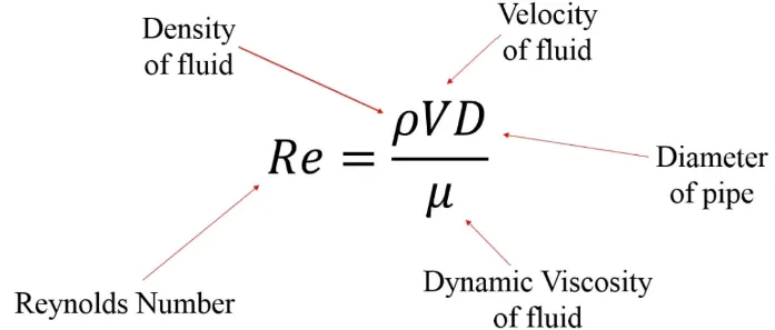
- Reynolds number
- Prandtl number

where,  = Prandtl number
 = momentum diffusivity
 = thermal diffusivity
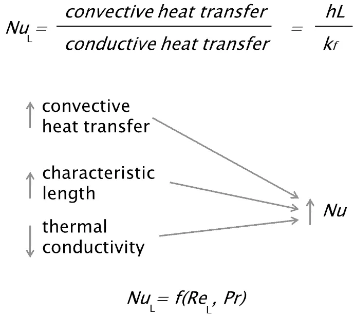
- Nusselt number
- Heat transfer coefficient
 where , h = heat transfer coefficient
 = Heat flux
 = difference in temperature between a solid surface and surrounding fluid
- Procedure
- Spaceclaim geometry
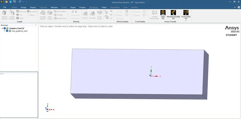
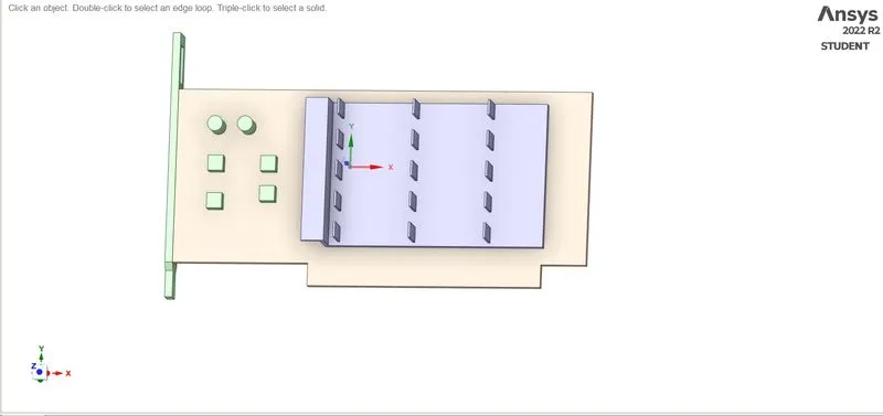
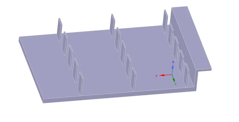
Fins
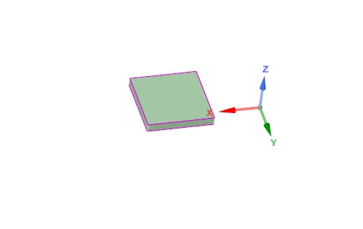
Processor
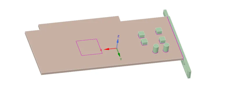
Base
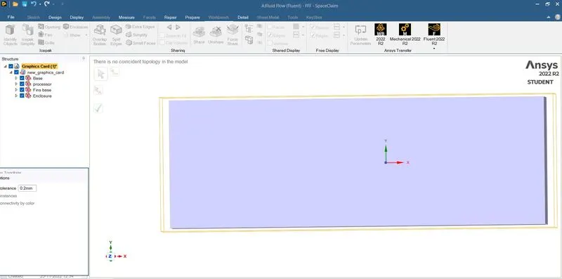
- Share topology
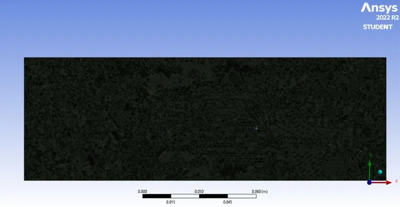
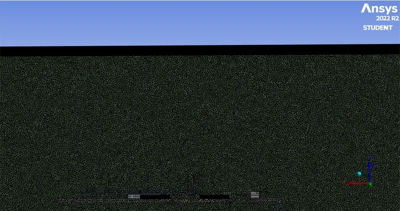
- Meshing
- Element size =0.003mm
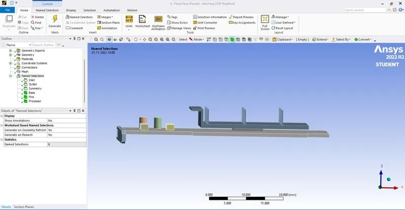
- Name selection
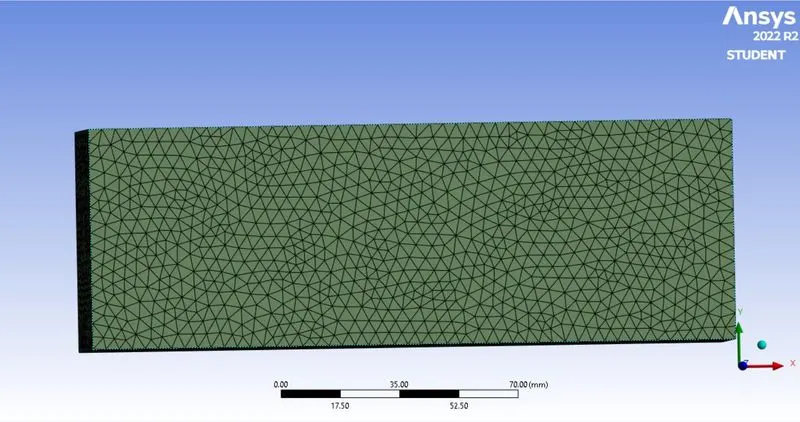
- Element size = 3.9 mm
-
Simulation Setup
1.Solver: Steady
2.Type: Pressure Based
3.Turbulence Model: k-Omega(SST)
4.Materials: Different materials are used for each part, some of which are custom created
Parts Material
Base Wood
Fins Aluminium
processor Silicon
-
Boundaries:
- Inlet:
Type: Velocity Inlet
Velocity: 1m/s
Temperature: 300 K
- Outlet:
Type: Pressure Outlet
Pressure: 0 Pa(Gauge Pressure)
Temperature: 300 K
-
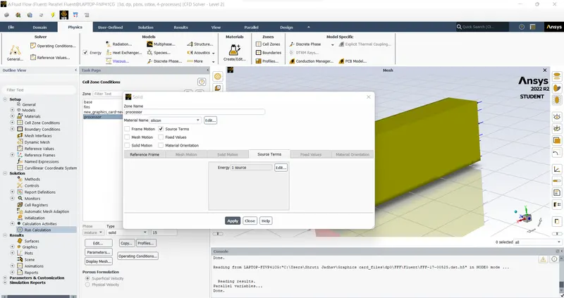
The processor is assumed as the only source of heat. The heat generated by the processor is calculated as:-
Graphics Card Power = 1 W
Volume of the card = 8 x 8 x 1
= 64mm3
Heat Generated = P/V=1 / 64e−9
= 15625000W /m^3
-
Solution
- Method: Standard
- Number of Iterations: 800
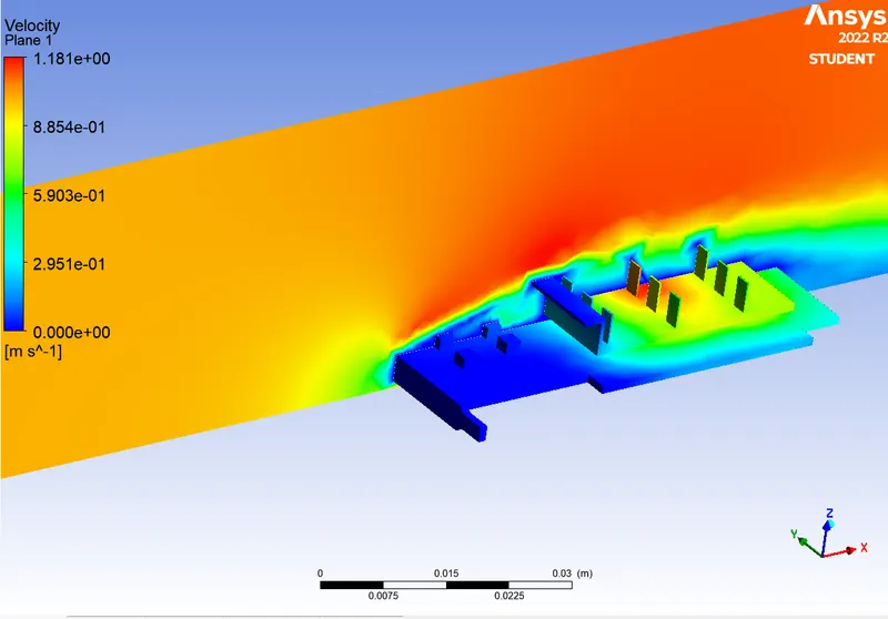
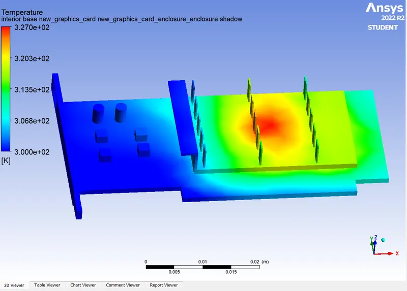
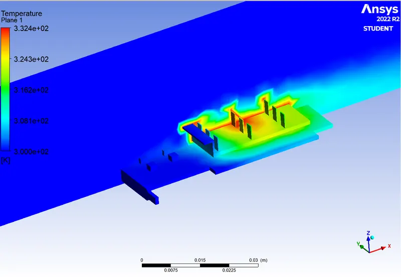
- Velocity = 1 m/s
- Velocity contour
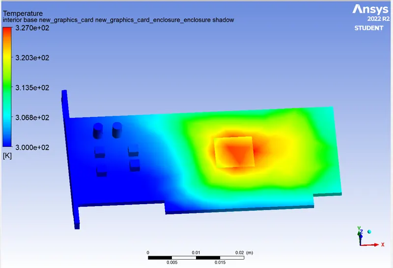
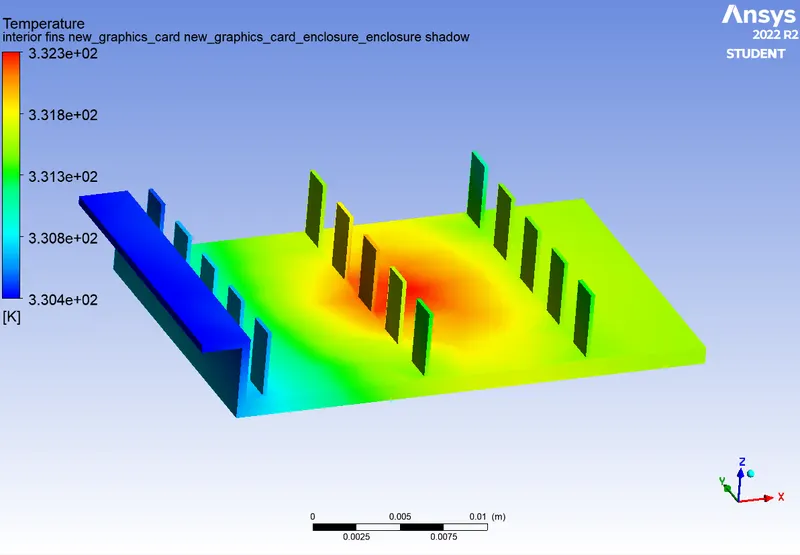
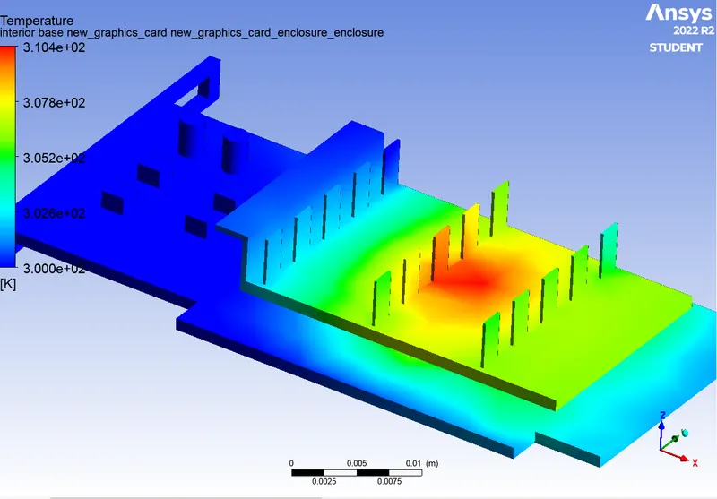
- Temperature contour
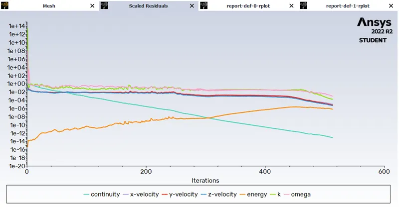
- Residuals
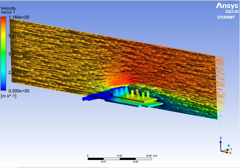
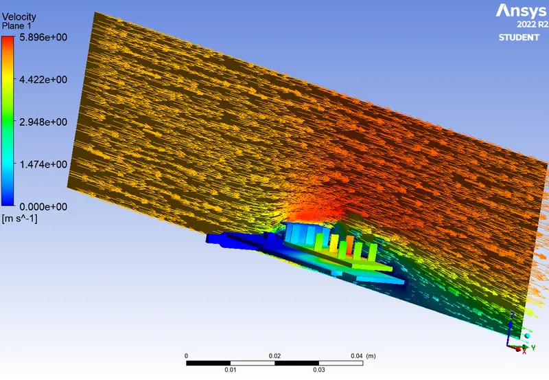
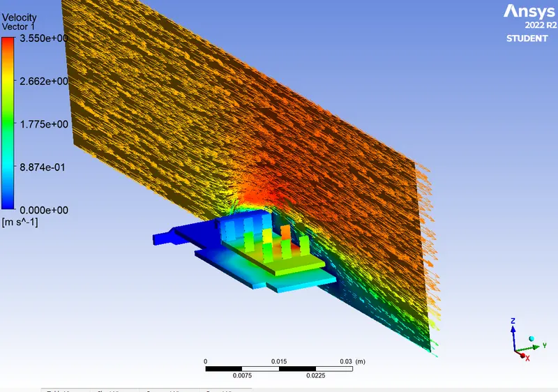
- Velocity vector plot
- Base
- Fins
- Processor
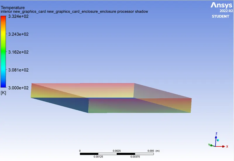
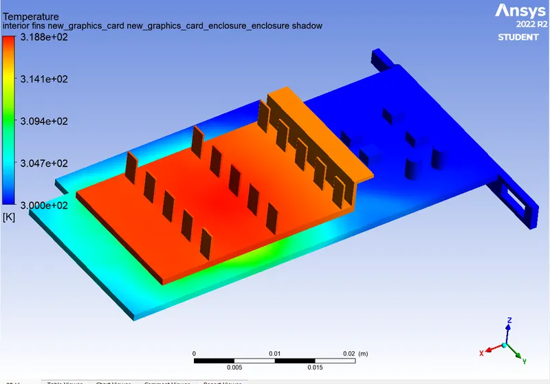
- Hotspot region - Region of Maximum temperature
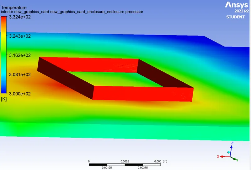
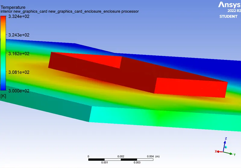
- Velocity = 5 m/s
- Results
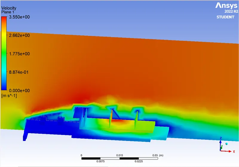
- Velocity contour
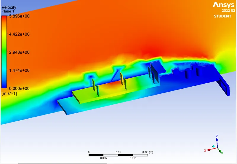
- Processor hotspot Region
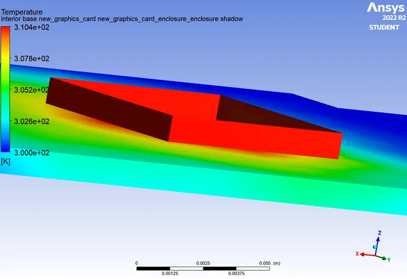
- Temperature contour
- Vector plot
- Velocity = 3 m/s
- Results
- Velocity contour
- Temperature contour
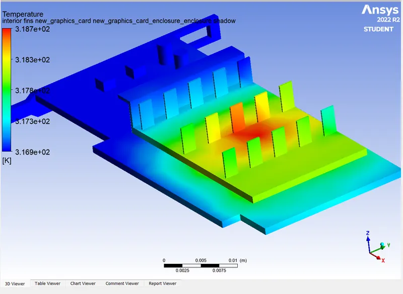
- Hotspot Region
- Vector plot
- Results
- Stepwise explaination
- CHT analysis requires the both the solid and the liquid volume under consideration spaceclaim gives an option of volume extract for selecting the edges for fluid volume.
- Both solid and liquid components are copied into one component.
- Creating shared topology.
- Spaceclaim now provides an option to split the match topology when you choose to split match topology. The meshes of the fluid and solid volumes should match each other. This is a prerequisite for CHT analysis.
- Loads the correct geometry into the outlet port and simulates it for the computer-generated base mesh.
- To study the effects of liquid-to-wall convection, named selections such as inlet, outlet, outlet, and wall convection are used to remove heat from the wall by conduction methods.
- A baseline mesh created from the original geometry without modification.
- Then import it into the Fluent solver to run a CHT flux heat transfer analysis.
- The velocity at the inlet is v = 5 m/s, 1mls and 3 mls are given for various conditions and the temperature of the fluid is 300 Kelvin.
- The boundary condition applied to the inlet is Velocity Inlet.
- 3 different materials are given for fins ,base and processor.
- A steady pressure-based solver is used in the SIMPLE algorithm and the turbulence model used in the k-ε turbulence model is used at the outlet.
- Contours are plotted for temperature , velocity and heat transfer coefficient.
- Cell Zones condition
- Conclusion
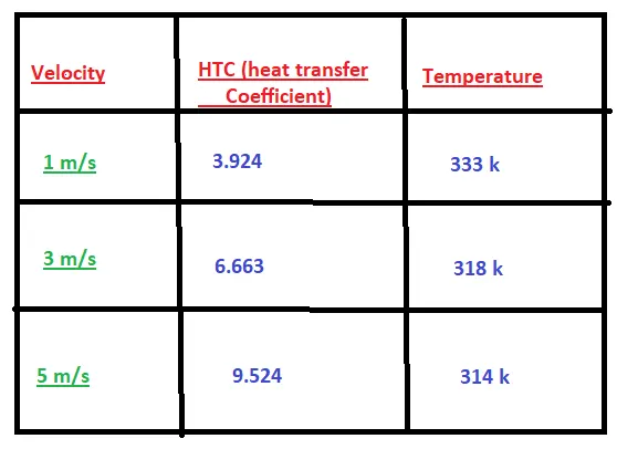
- From the table above, it is very noticeable that the net temperature of the graphics card components decreases with increasing air intake speed.
- It can be concluded that higher inflow velocities provide better cooling, lower average temperatures, and protect components from damage.
- Furthermore, it can be observed that the temperature of the components increases when the inlet velocity is decreased from 5 m/s to 1 m/s. This also proves that the higher the speed, the better the cooling.