Week 6 - CHT Analysis on a Graphics card
Aim: Analysis of steady-state conjugate heat transfer using a graphics card model
Objectives :
- Run the simulation by varying the velocity from 1m/sec to 5m/sec for at least 3 velocities and discuss the results.
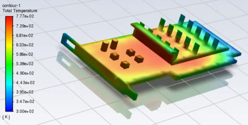
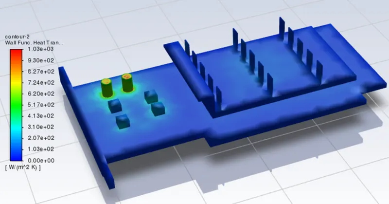
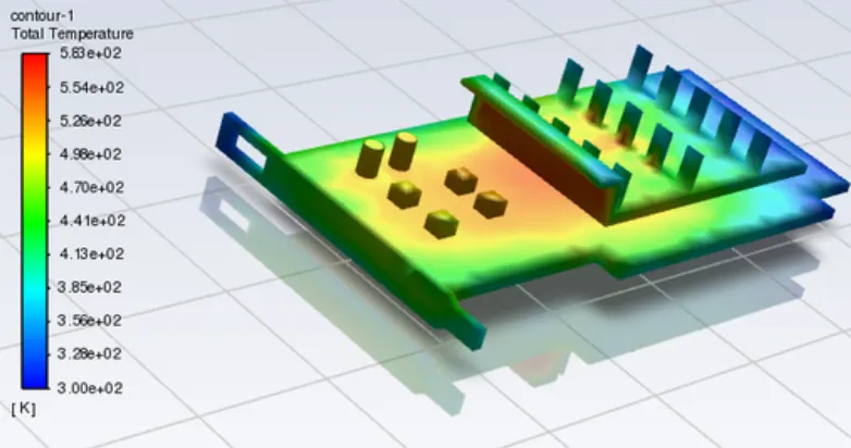
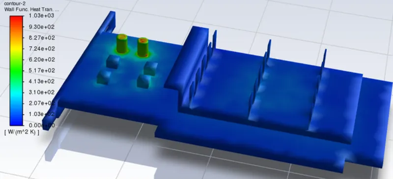
- Find out the maximum temperature and heat transfer coefficient attained by the processor.
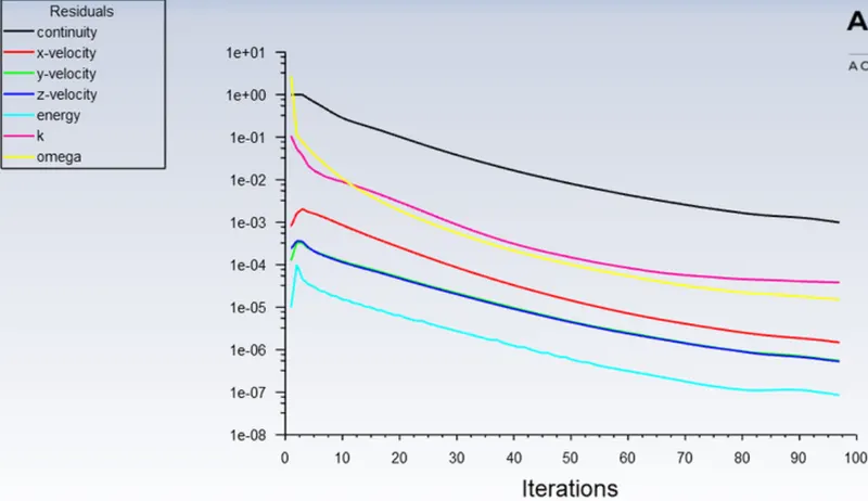
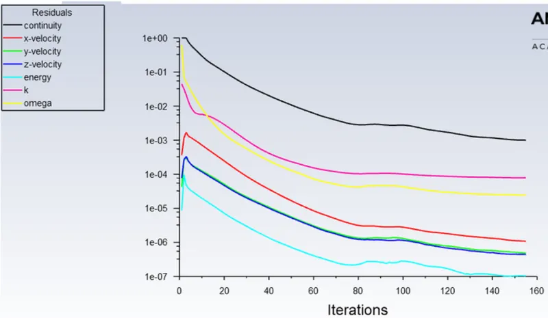
- Prove that the simulation has achieved convergence with appropriate images and plots.
- Identify potential hotspots on the model.
Solving & Modelling approach
- Graphic card file is loaded into the spaceclaim
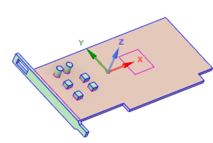
- The graphics card consists of a processor, PCB base, aluminum fin base, memory cards, and capacitors.
- The solid and liquid volume under consideration are both necessary for CHT analysis, and Spaceclaim offers a volume extract option for choosing edges for fluid volume. In this case, the solid and liquid volume under consideration are air and the components of the graphics card.
- the underlying theory of how air carries away the heat produced by the CPU. The aluminium fin is utilised to increase the heat transfer surface area.
- The share topology is configured to make the mesh conformal and to lower interpolation error.
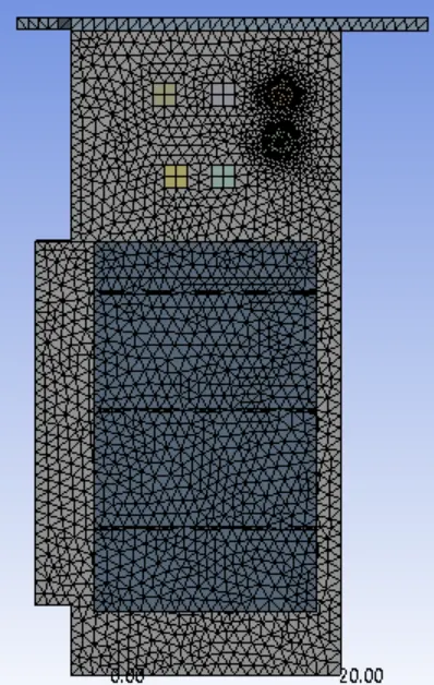
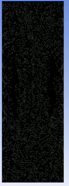
- The meshing window is then loaded, where the named selection is made and the baseline mesh and refined mesh are set.
- The construction of the material is chosen with the fluid material and the solid material separated.
- To comprehend the behaviour of temperature, velocity, and surface heat transfer coefficient at the interface, the relevant contour images and graphs are reviewed.
Geometry:
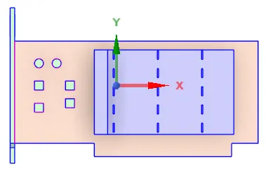
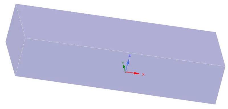
Processor-
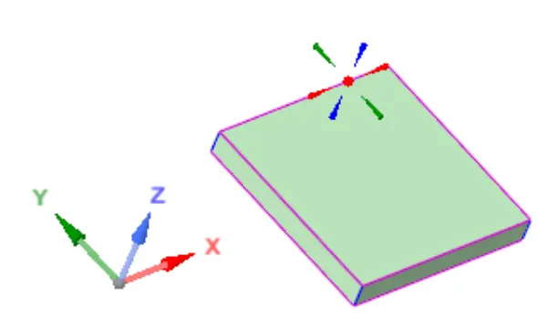
Fins:
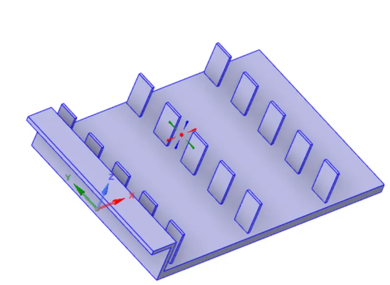
Base-
Meshing:
We start the mesh by naming the parts
1. Inlet
2. outlet
3. Wall symmetry
4. components
5. Fins
6. Base
7. Processor
Setup:
|
Solver Type |
Pressure-Based |
|
|
Velocity Formulation |
Absolute |
|
|
Time |
|
|
|
Models |
Viscous model: K-omega SST Energy model: On |
|
|
Material |
Fluid type: Air Solid-type: Aluminium : gold : copper |
|
|
Cell zones |
Fluid type: Air Solid: Al, Au, Cu |
|
|
Boundaries |
Inlet : inlet velocity: 2m/s : temperature = 300K Outlet: outlet pressure = 0 |
|
|
Reference values |
Standard |
|
|
Initialization |
Standard |
Usually, the power consumed by a processor is converted into heat energy. To calculate the heat generated on the processor which is = Power consumed divided by the total volume of the processor
"The power consumption of today's graphics cards has increased a lot. The top models demand between 110 and 270 watts from the power supply; in fact, a powerful graphics card under full load requires as much power as the rest of the components of a PC system combined"
Taking this fact we will assume the power consumed to be 55 (being half of the upgraded graphic card)
Heat generated = 55/(64⋅10^−9)W/m3=859375000 W/m3
Results:
Residuals:
Temperature:
Wall heat transfer coefficient:
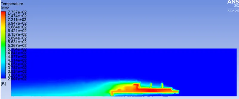
Temperature contours:
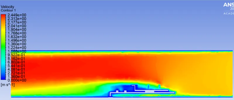
Velocity contours:
CASE 2:
SIMULATIONS
|
SETUP |
||
|
Solver Type |
Pressure-Based |
|
|
Velocity Formulation |
Absolute |
|
|
Time |
|
|
|
Models |
Viscous model: K-omega SST Energy model: On |
|
|
Material |
Fluid type: Air Solid-type: Aluminium : gold : copper |
|
|
Cell zones |
Fluid type: Air Solid: Al, Au, Cu |
|
|
Boundaries |
Inlet : inlet velocity: 5m/s : temperature = 300K Outlet: outlet pressure = 0 |
|
|
Reference values |
Standard |
|
|
Initialization |
Hybrid |
Residuals:
Temperature on Graphic card:
Wall heat transfer coefficient:
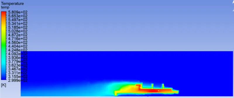
Temperature contour:
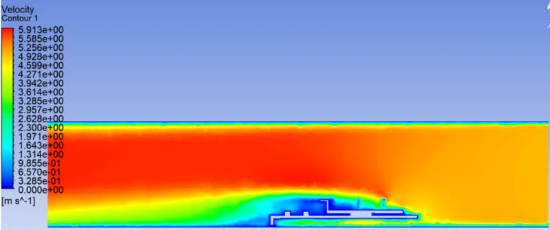
Velocity contour:
Conclusion:
- Higher velocity in a particular region means a higher Reynolds number. That’s why the heat transfer coefficient in that area is highest, which means the maximum amount of heat transfer is taking place from fluid to the solid in that region. This also results in a higher temperature of solid in that location.
- Heat transfer coefficient is a function of properties of the fluid at film temperature, temperature difference, temperature coefficient, buoyance force et, hence, mesh resolution near walls usually has the biggest impact on numerical results.
- For the turbulent models, we have to take care of the assumptions and the boundary conditions you put in the program. The mesh is a very important parameter to get nice results so we have to refine it in the important place of our drawing.
- Some factors that should be considered which the most significant is the turbulent boundary layer. If we are using any kind of low Reynolds turbulence model considering enhanced wall treatment (as your K-w SST model), so we need to make sure that we stay in the laminar sub-layer region where velocity profiles are assumed to be laminar and viscous stress dominates the wall shear which means
- Mesh/ grid dependency test is very important to get confidence over results