Week 6 - CHT Analysis on a Graphics card
AIM :
To simulate a steady state flow over a given graphic card model by varying the inlet velocity of air as 1 m/s, 3 m/s and 5 m/s and perform the conjugate heat transfer analysis on the given graphic card model.
OBJECTIVES :
- To import the given model into spaceclaim and perform share topology.
- To generate mesh for the given model by selecting different mesh element size for different cases to perform the mesh independency study.
- To setup the simulation by assigning required materials for different cell zone regions of the model and providing the heat generation rate from the processor as the heat source.
- To provide the required boundary conditions for all the regions of the model and vary its inlet velocity for different cases of simulations.
- To post process the results.
INTRODUCTION :
We are going to simulate the flow over a given graphic card model and perform the CHT analysis on the graphic card. In real world application, the processor in the graphic card generates heat which is reduced by the flow of air over the processor by use of the cooling fan present in some computers. Also, In order to increase the heat transfer rate of the processor with the surrounding air flowing over it, fins are placed above the processor. Fins are nothing but a extended surface which increase the heat transfer rate by means of convection. So, we are going to provide the heat source to the processor from which the heat is dissipated to the air flowing around it and also perform the CHT analysis for different cases by varying the inlet velocity of air as 1m/s, 3m/s and 5m/s and compare the results.
CHT means Conjugate Heat Transfer. It is the analysis done for finding heat transfer which occurs by means of both conduction( due to direct molecular interactions ) and convection( due to fluid bulk motion ). It is a analysis of heat transfer between a solid and fluid domain by exchanging the thermal energy at the interface between them.
Power density :
Power density is the amount of heat generation rate per unit volume.
It can be written as,
Power density of the processor = Heat generation rate by the processor / Total volume of the processor
CASE SETUP :
- Here, we run the simulation for four different cases. The first two cases is for performing the mesh independency study with base line mesh and refined mesh for inlet velocity of 3m/s . Then, choose the refined mesh for performing the simulation by varying the inlet velocity as 1 m/s and 5 m/s.
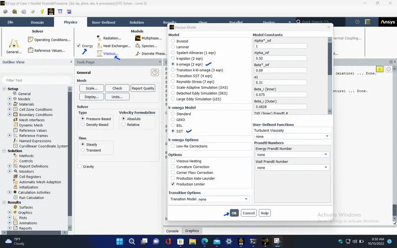
- The K-omega SST turbulence model is selected for this simulation, since the CHT analysis is mainly focussed over the graphic card region for which the K- omega SST will give more accurate results for the near wall conditions
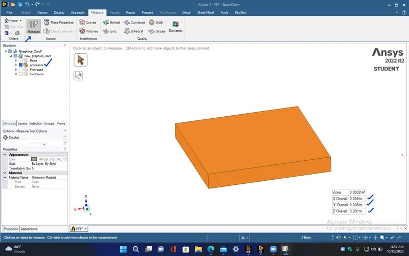
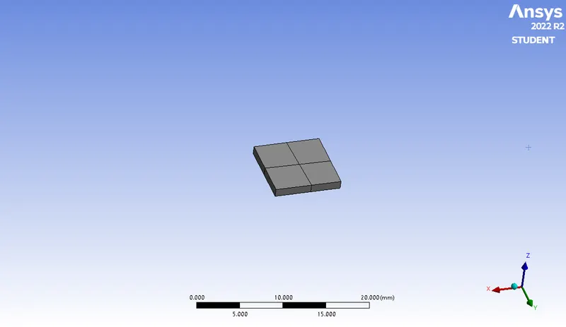
- We take the processor as the haet source. Assume the heat generation rate by the processor as 2 Watts, and the volume of the processor can be determined by measuring its dimensions in spaceclaim,
Hence the power density of the processor can be written as,
`q^. = 2 / (0.008 * 0.008 * 0.001)`
`q^. = 31250000 " W/m^3"`
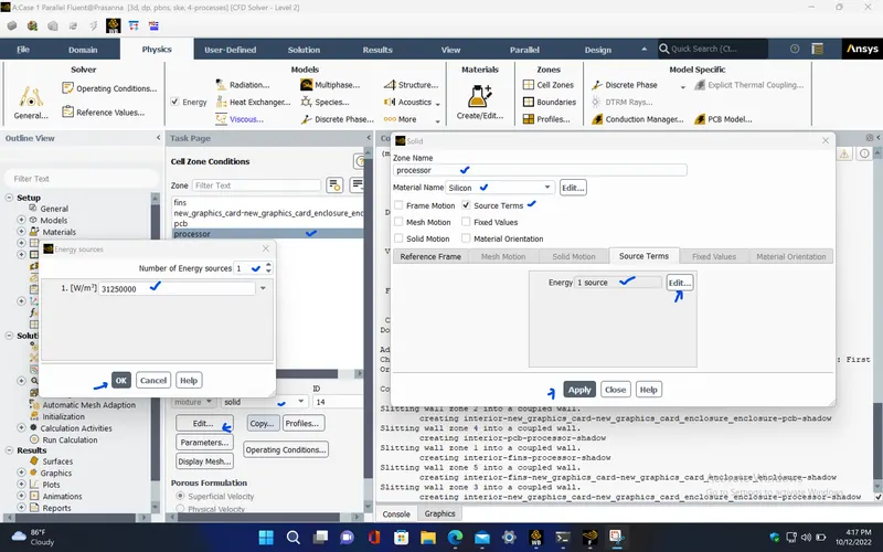
This value should be given under cell zone conditions of the processor which is taken as the heat source for this simulation.
Materials and its properties for different components of the graphic card :
For Fins, the material chosen is aluminium
Density = 2719 kg/m^3
Cp (Specific Heat) = 871 J/(kg K)
Thermal Conductivity = 202.4 W/(m K)
For Processor, the material is taken as silicon
Density = 2330 kg/m^3
Cp (Specific Heat) = 703 J/(kg K)
Thermal Conductivity = 153 W/(m K)
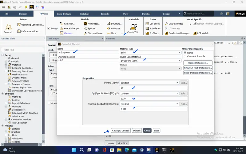
For PCB(Printed circuit board), the material is polystyrene
Density = 55 kg/m^3
Cp (Specific Heat) = 1210 J/(kg K)
Thermal Conductivity = 0.027 W/(m K)
PROCEDURE :
CASE - 1 (Base line mesh, V = 3 m/s) :
PRE-PROCESSING :
- Open spaceclaim from the Ansys fluent flow system in workbench. Import the given graphic card model into spaceclaim and measure the dimensions of the processor using measure tool. This dimensions can be used to find the volume of the processor which can be used in determining the power density of the processor.
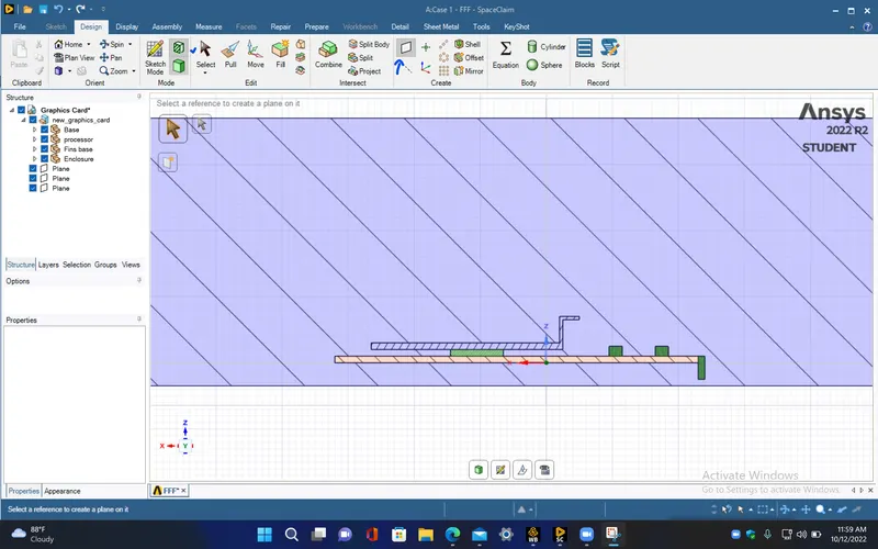
- Cross sectional view of the graphic card model which is enclosed within its fluid domain.
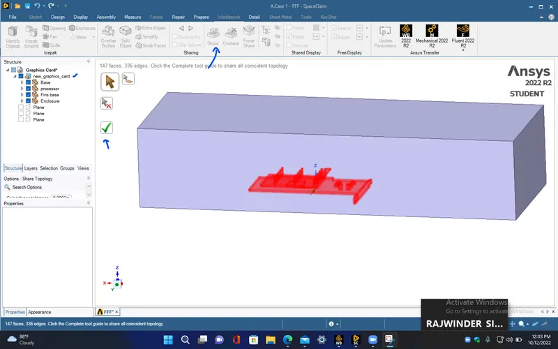
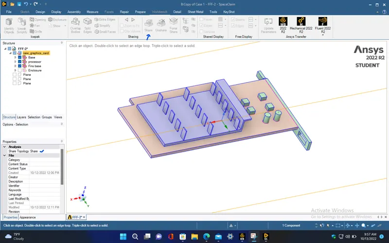
- Use share topology option under workbench menu bar. This will help to create the conformal mesh by sharing common node points between any intermediate surfaces.
- Open the mesh window from Ansys fluent flow and give necessary names to different components of the model.
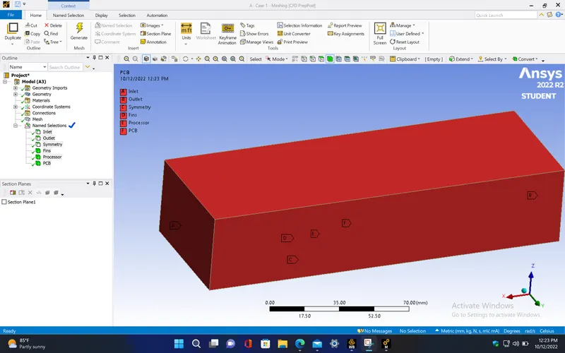
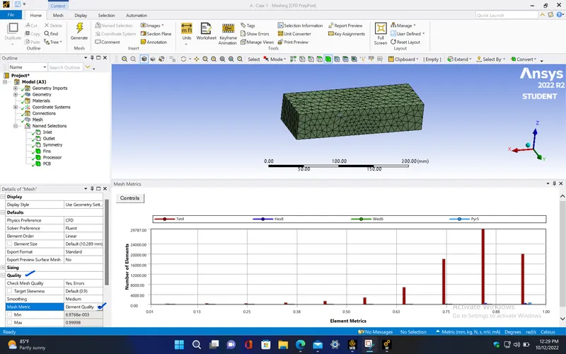
- Now, generate the mesh. This will generate the base line mesh for the model with default mesh element size which is chosen automatically by the fluent software depending upon the bounding box created for different components by the fluent software.
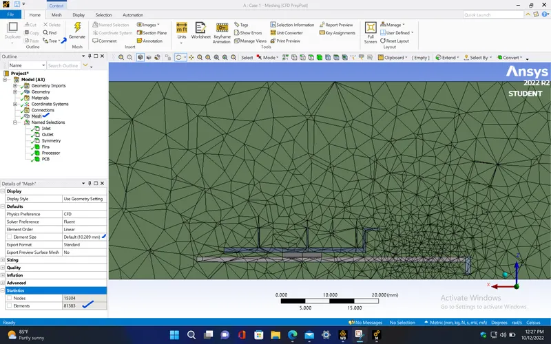
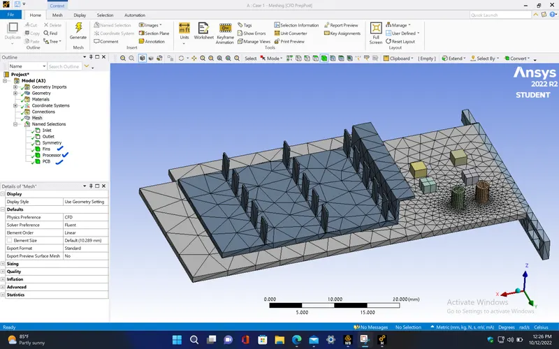
- Processor
|
Cells |
Faces |
Nodes |
|
81383 |
168984 |
17471 |
- Here, most number of mesh elements have about 88% of the element quality and so the model can be proceeded for setup.
SETUP AND SOLVING :
- Setup the problem by selecting the required solver and boundary conditions for this simulation. The selected solver models and boundary conditions for running this simulation are as follows,
|
Model |
Settings |
|
Space |
3D |
|
Time |
Steady |
|
Viscous |
SST k-omega turbulence model |
|
Heat Transfer |
Enabled |
Materials properties :
|
Fluid |
air |
|
Density |
1.225 kg/m^3 |
|
Cp (Specific Heat) |
1006.43 J/(kg K) |
|
Thermal Conductivity |
0.0242 W/(m K) |
|
Viscosity |
1.7894e-05 kg/(m s) |
|
Molecular Weight |
28.966 kg/kmol |
|
Solid |
polystyrene |
|
Density |
55 kg/m^3 |
|
Cp (Specific Heat) |
1210 J/(kg K) |
|
Thermal Conductivity |
0.027 W/(m K) |
|
Solid |
silicon |
|
Density |
2330 kg/m^3 |
|
Cp (Specific Heat) |
703 J/(kg K) |
|
Thermal Conductivity |
153 W/(m K) |
|
Solid |
aluminum |
|
Density |
2719 kg/m^3 |
|
Cp (Specific Heat) |
871 J/(kg K) |
|
Thermal Conductivity |
202.4 W/(m K) |
Cell zone conditions :
|
Fluid |
|
|
new_graphics_card-new_graphics_card_enclosure_enclosure |
|
|
Material Name |
air |
|
Solid |
|
|
processor |
|
|
Material Name |
silicon |
|
Source Terms |
|
|
energy |
31250000 |
|
fins |
|
|
Material Name |
aluminum |
|
pcb |
|
|
Material Name |
polystyrene |
Boundary conditions :
|
Inlet |
|
|
inlet |
|
|
Reference Frame |
Absolute |
|
Velocity Magnitude [m/s] |
3 |
|
Temperature [K] |
300 |
|
Outlet |
|
|
outlet |
|
|
Gauge Pressure [Pa] |
0 |
|
Backflow Total Temperature [K] |
300 |
|
Symmetry |
|
|
symmetry |
symmetry |
|
Wall |
|
|
interior-fins-processor-shadow |
|
|
Material Name |
silicon |
|
Thermal BC Type |
Coupled |
|
interior-fins-processor |
|
|
Material Name |
silicon |
|
Thermal BC Type |
Coupled |
|
interior-pcb-processor-shadow |
|
|
Material Name |
silicon |
|
Thermal BC Type |
Coupled |
|
interior-pcb-processor |
|
|
Material Name |
silicon |
|
Thermal BC Type |
Coupled |
|
interior-fins-new_graphics_card-new_graphics_card_enclosure_enclosure-shadow |
|
|
Material Name |
aluminum |
|
Thermal BC Type |
Coupled |
|
interior-fins-new_graphics_card-new_graphics_card_enclosure_enclosure |
|
|
Material Name |
aluminum |
|
Thermal BC Type |
Coupled |
|
Wall Motion |
Stationary Wall |
|
Shear Boundary Condition |
No Slip |
|
interior-new_graphics_card-new_graphics_card_enclosure_enclosure-processor-shadow |
|
|
Material Name |
silicon |
|
Thermal BC Type |
Coupled |
|
Wall Motion |
Stationary Wall |
|
Shear Boundary Condition |
No Slip |
|
interior-new_graphics_card-new_graphics_card_enclosure_enclosure-processor |
|
|
Material Name |
silicon |
|
Thermal BC Type |
Coupled |
|
interior-new_graphics_card-new_graphics_card_enclosure_enclosure-pcb-shadow |
|
|
Material Name |
polystyrene |
|
Thermal BC Type |
Coupled |
|
interior-new_graphics_card-new_graphics_card_enclosure_enclosure-pcb |
|
|
Material Name |
polystyrene |
|
Thermal BC Type |
Coupled |
|
Wall Motion |
Stationary Wall |
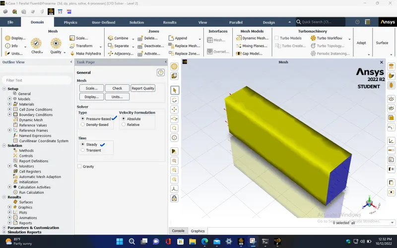
- For this simulation, K omega SST turbulence model is preferred since the CHT analysis is done near to the wall surface area of the graphic card model.
- Since the chosen materials for different components of the graphic card were not available in the fluent database, those materials need to be created. This can be done by copying any of the existing material present in fluent database and giving the new material name with its properties to it.
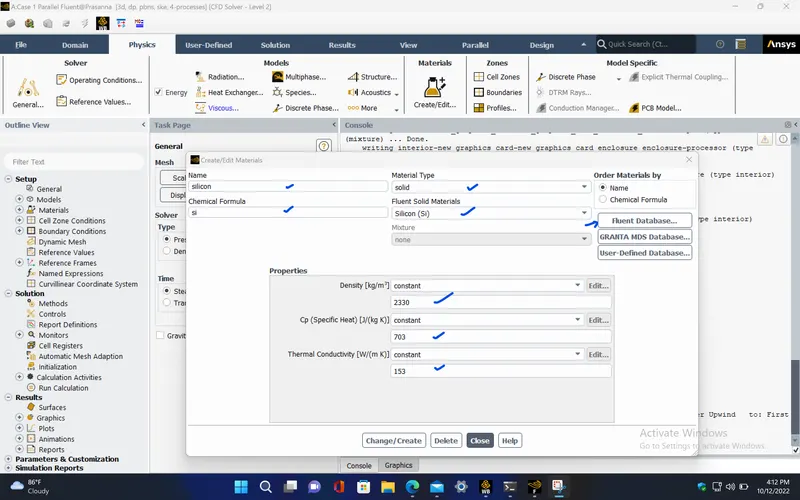
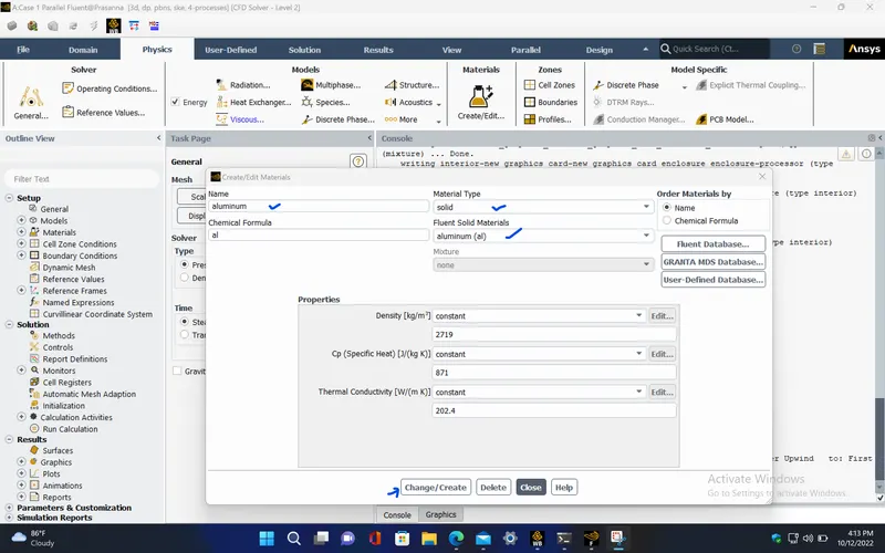
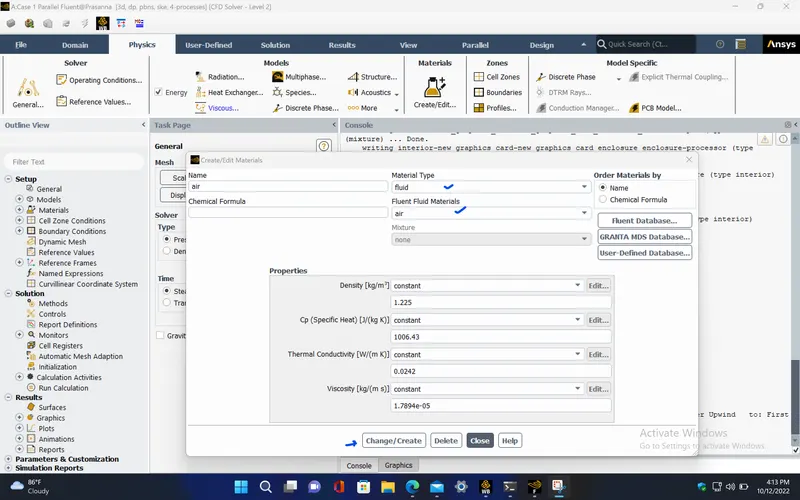
- Now, assigning required cell zone conditions for the components.
- For PCB (Printed circuit boards), polystyrene (C8H8) is selected.
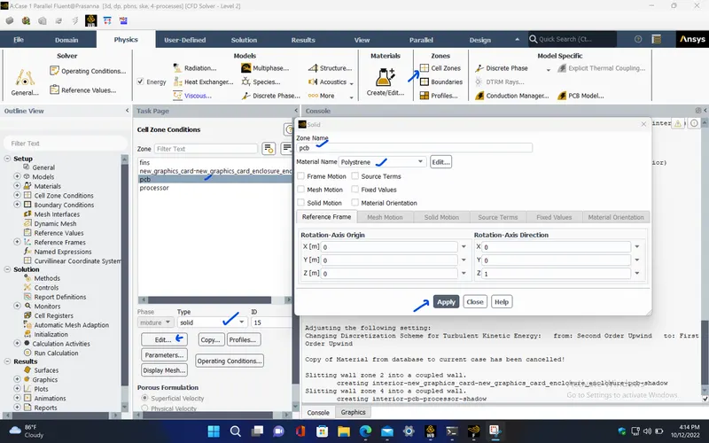
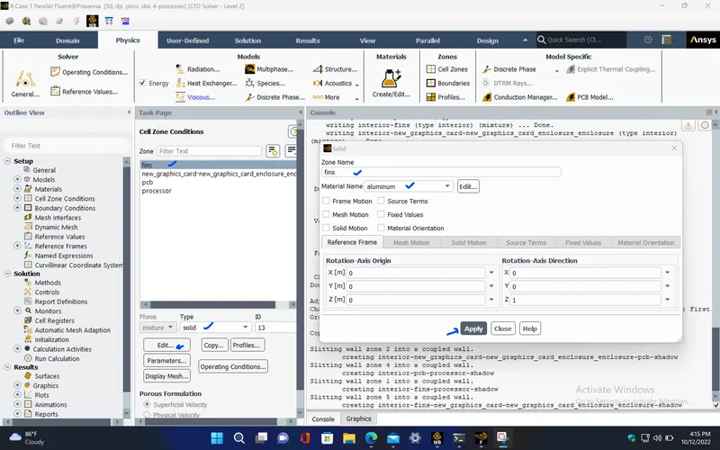
- For Fins, aluminium is selected.
- For Processor, Silicon is selected. Here, the processor is the heat source from where the heat is being generated. So, select the processor as the source term and give the required value for power density which was calculated before.
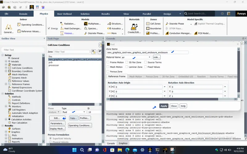
- The fluid domain is set as fluid type with air as the fluid.
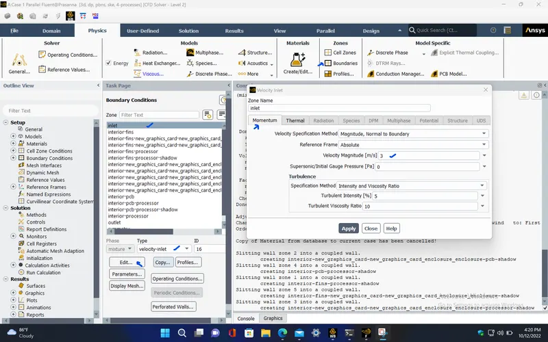
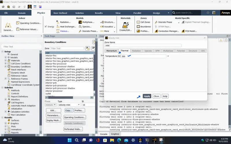
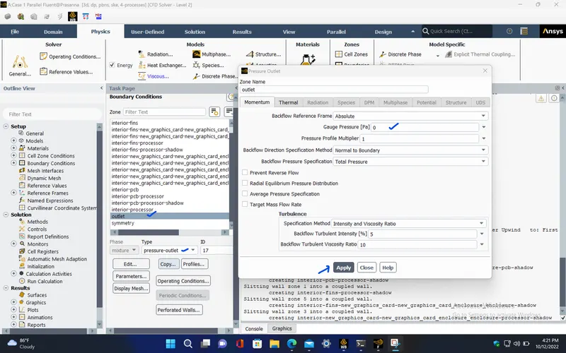
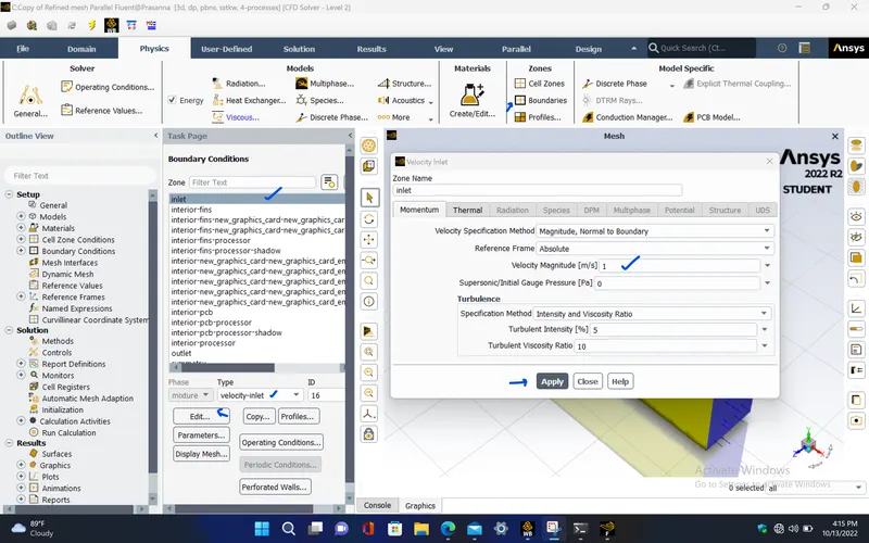
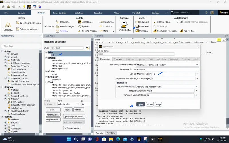
- For the inlet boundary condition, select velocity inlet and give the velocity as 3 m/s and also provide the temperature as 300K.
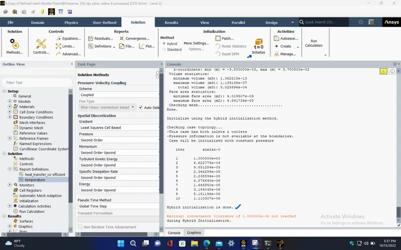
- Initializing the simulation.
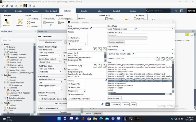
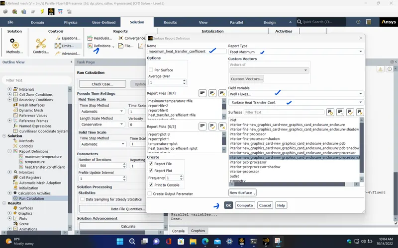
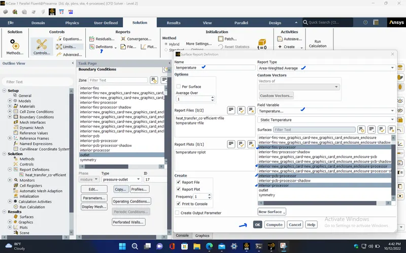
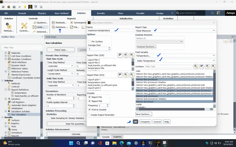
- Creating required report definitions for the simulaion.
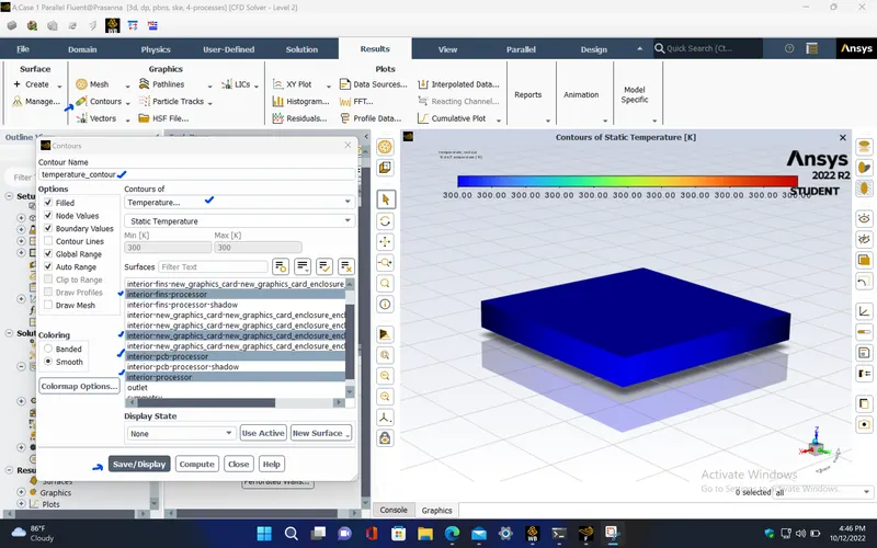
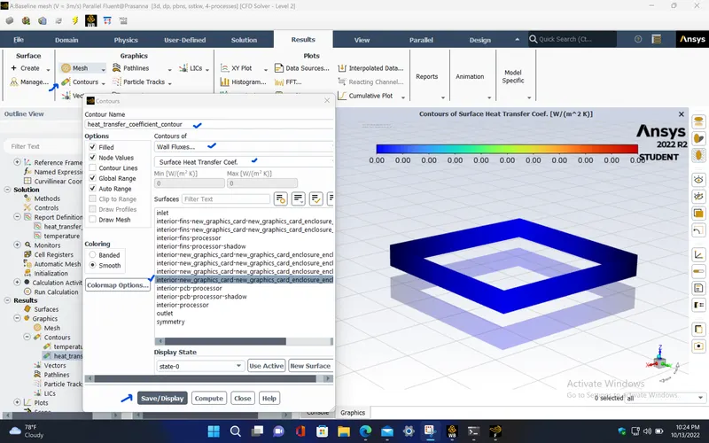
- Creating the contours.
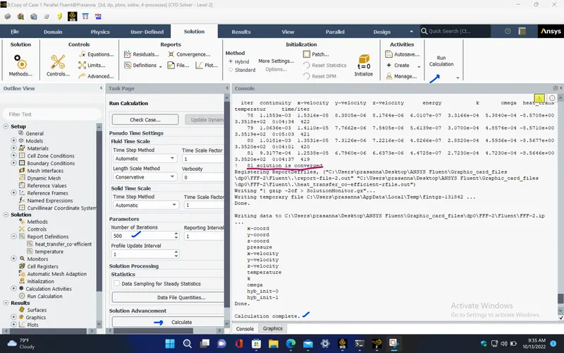
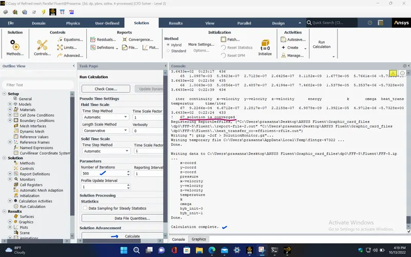
- Running the simulation for 500 iterations.
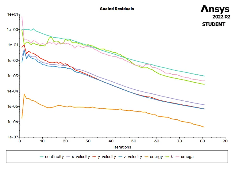
RESIDUALS PLOT :
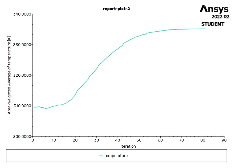
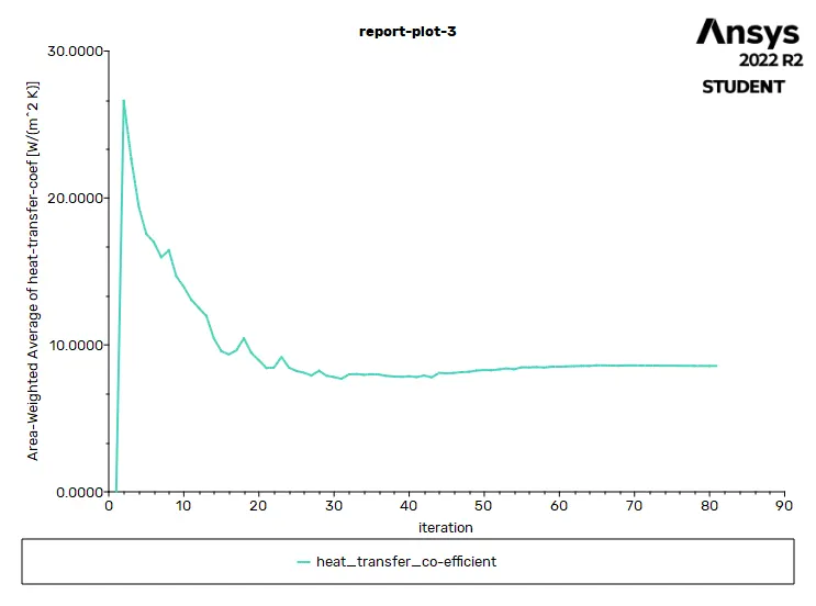
AVERAGE TEMPERATURE PLOT (Processor) :
AVERAGE HEAT TRANSFER COEFFICIENT PLOT (Processor) :
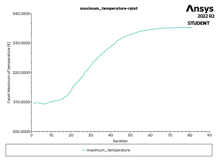
MAXIMUM TEMPERATURE PLOT (Processor) :
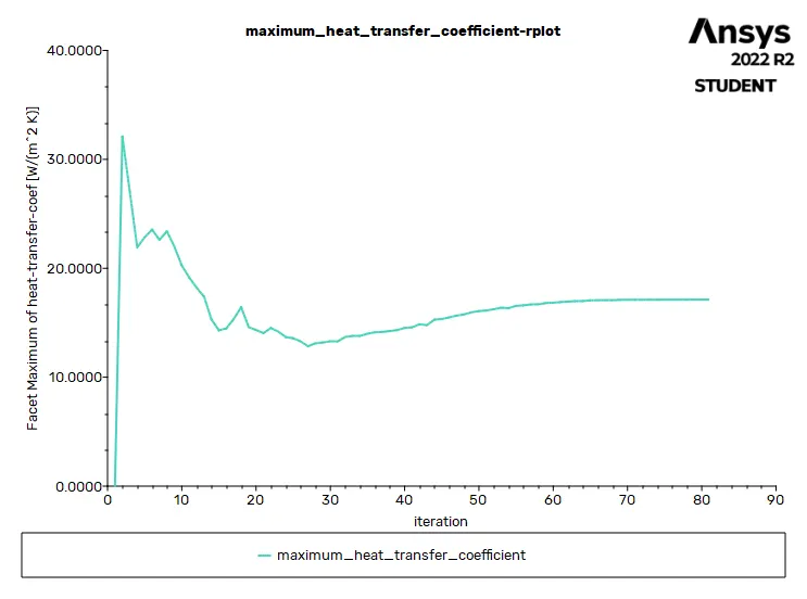
MAXIMUM HEAT TRANSFER COEFFICIENT PLOT (PROCESSOR) :
Solution status :
- From the above plots, we see that the solution got converged at 81th iteration since the rate at which residuals, velocity, drag co-efficient and lift co-efficient changes becomes constant over iteration.
Number of iteration - 81
|
Value |
Absolute Criteria |
Convergence Status |
|
|
continuity |
0.0009317724 |
0.001 |
Converged |
|
x-velocity |
1.253753e-05 |
0.001 |
Converged |
|
y-velocity |
6.795998e-06 |
0.001 |
Converged |
|
z-velocity |
6.637334e-06 |
0.001 |
Converged |
|
energy |
4.472833e-07 |
1e-06 |
Converged |
|
k |
0.0002723018 |
0.001 |
Converged |
|
omega |
0.0004723034 |
0.001 |
Converged |
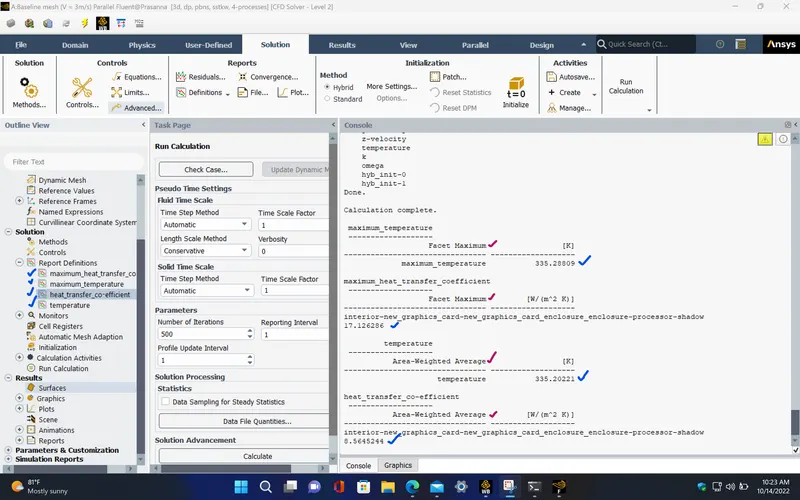
Report definitions :
|
temperature |
335.2022 |
K |
|
heat_transfer_co-efficient |
8.564524 |
W/(m^2 K) |
|
maximum_temperature |
335.28809 |
K |
| maximum_heat_transfer_coefficient | 17.126286 | W/(m^2 K) |
POST PROCESSING :
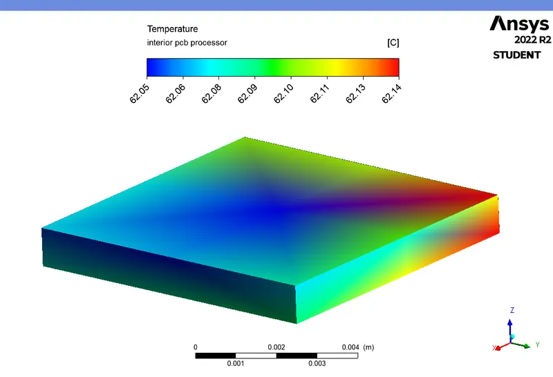
TEMPERATURE CONTOUR (Processor) :
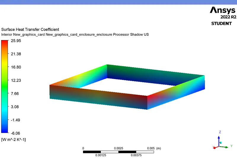
HEAT TRANSFER COEFFICIENT CONTOUR (Processor) :
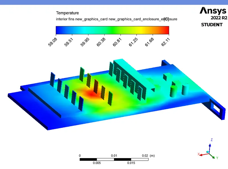
TEMPERATURE CONTOUR (Fins, PCB, Processor) :
TEMPERATURE CONTOUR (XZ plane) :
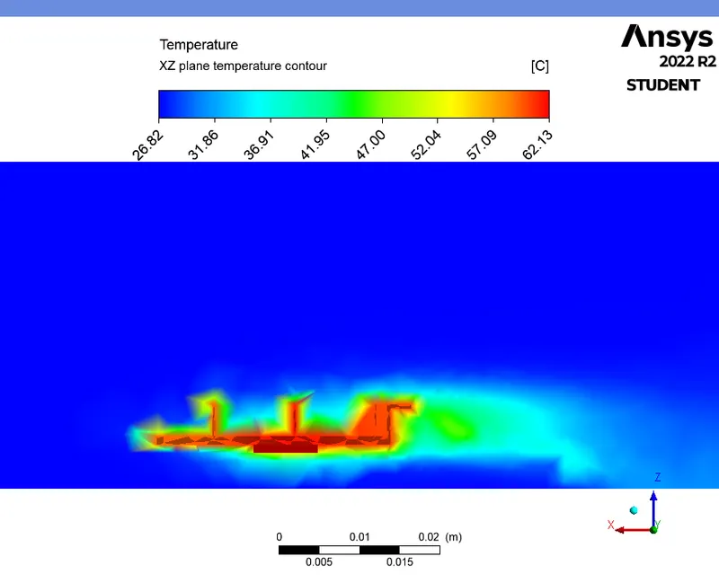
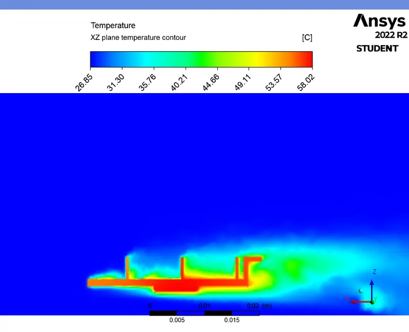
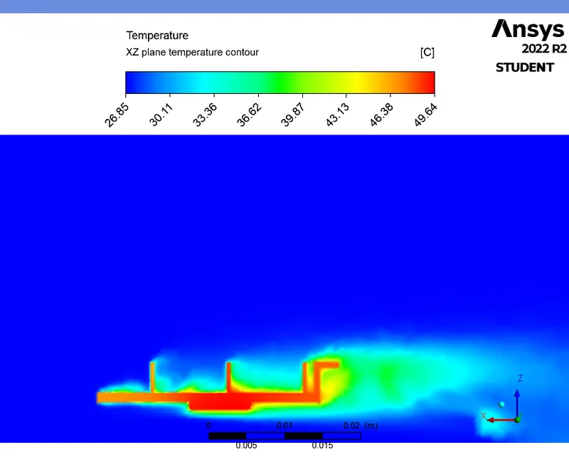
- From the above temperature contour, we can see that, the contour is more distorted since it is a base line mesh which has fewer number of mesh elements. Hence, the temperature is not captured properly at that regions.
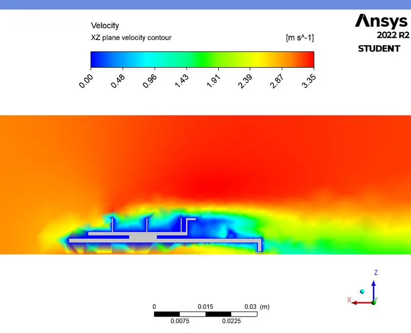
VELOCITY CONTOUR (XZ plane) :
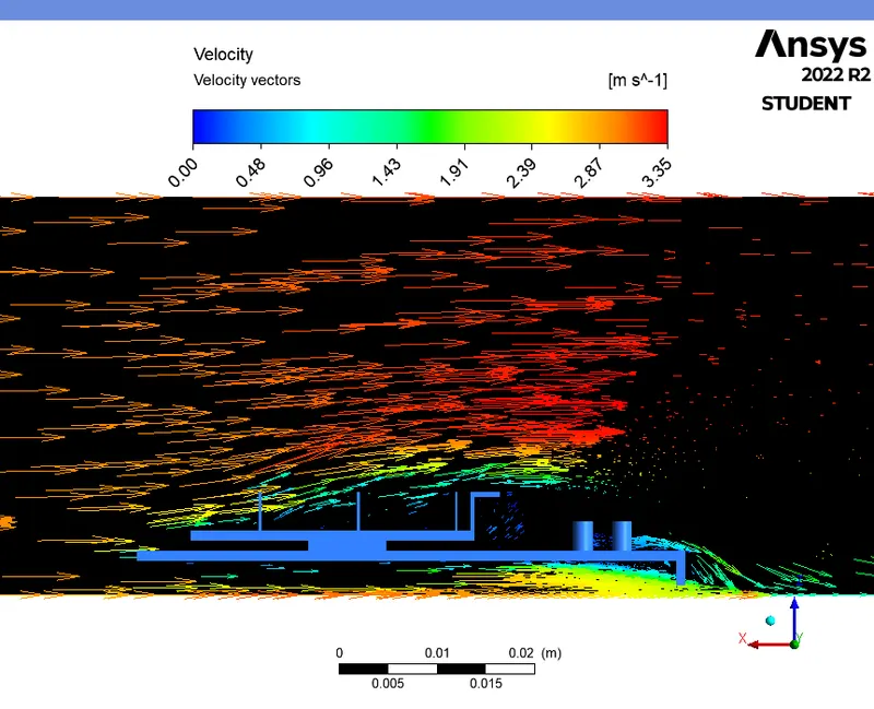
VELOCITY VECTORS (XZ plane) :
CASE - 2 (Refined mesh, V = 3 m/s) :
PRE-PROCESSING :
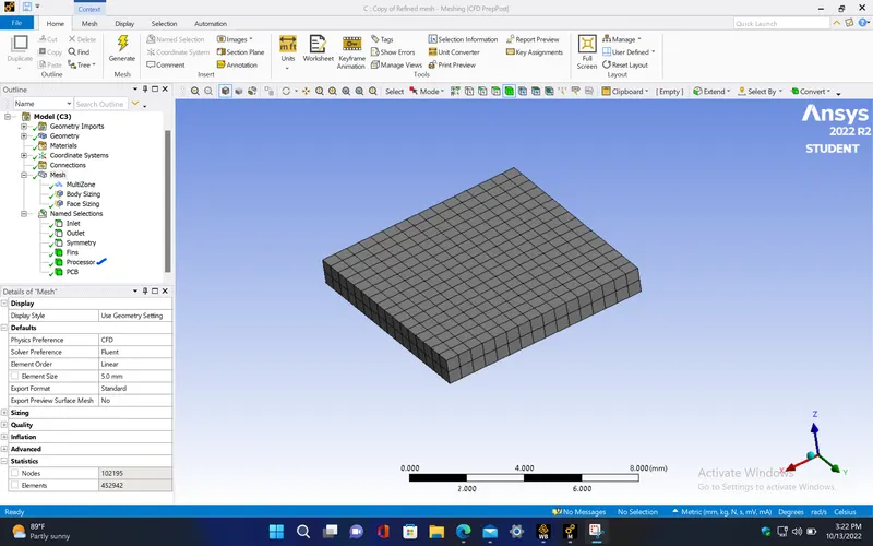
- For this case, to create a refined mesh, insert sizing option for the graphic card components with the element size of 0.5 mm.
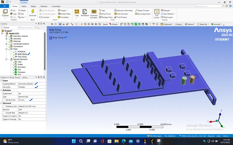
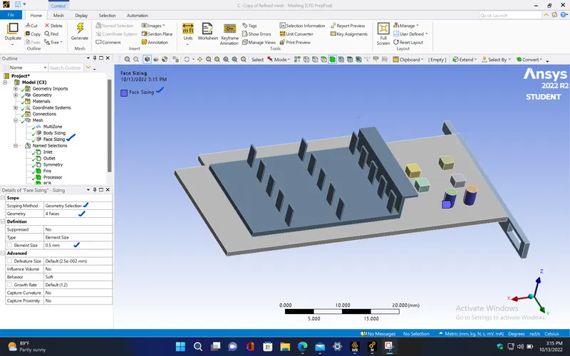
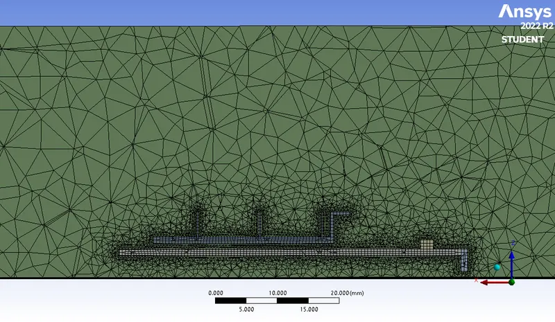
- Since the given model doesn't contain any complex geometry regions, the hexahedral mesh element type can be used in the given model in order to get more accurate results. So, Here, we use Multizone method which will create hexahedral mesh over the graphic card region and tetrahedral mesh in the fluid domain.
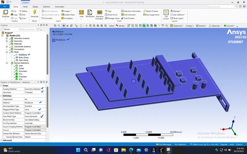
- The base element size for the model is taken as 5 mm and the mesh is generated.
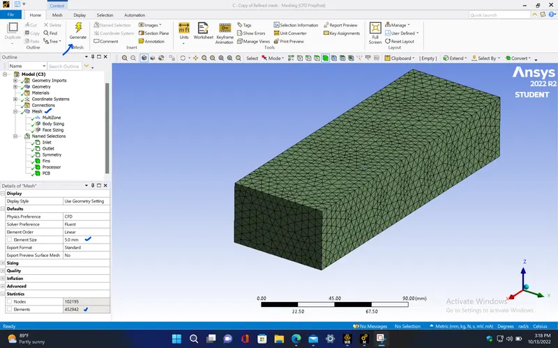
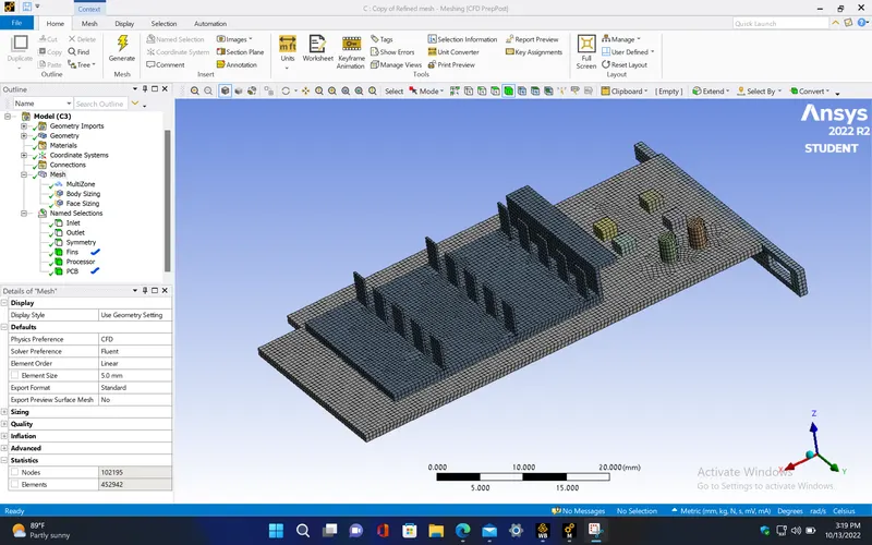
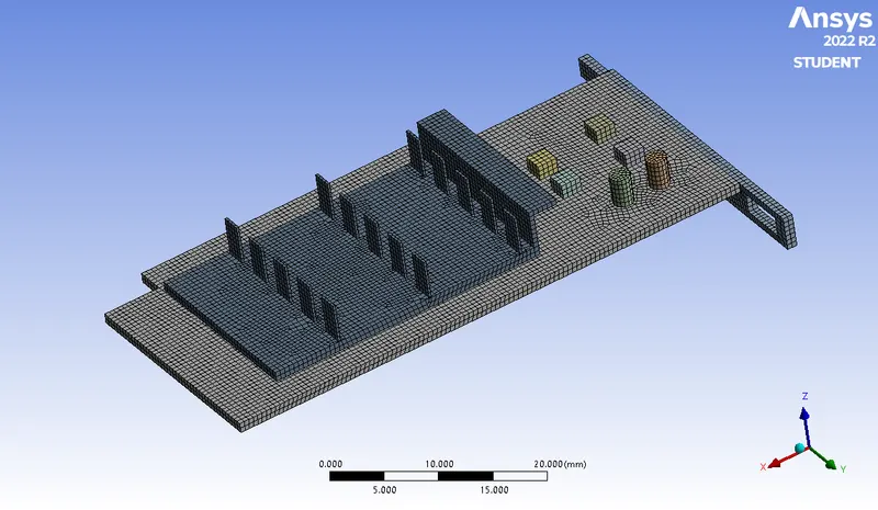
- Processor
|
Cells |
Faces |
Nodes |
|
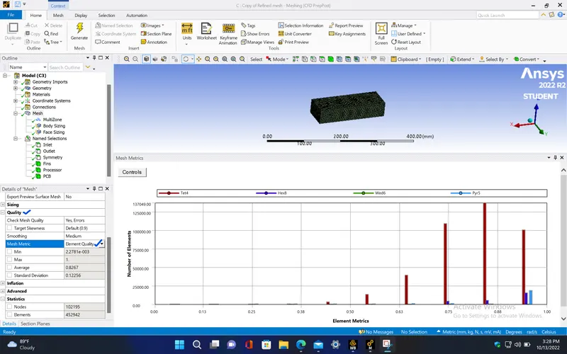
452942 |
966609 |
123286 |
- Since, most number of mesh elements have about 88% element quality, the model can be proceeded for setup.
SETUP AND SOLVING :
- Setup the problem by selecting the required solver and boundary conditions for this simulation. The selected solver models and boundary conditions for running this simulation are as follows,
|
Model |
Settings |
|
Space |
3D |
|
Time |
Steady |
|
Viscous |
SST k-omega turbulence model |
|
Heat Transfer |
Enabled |
Materials properties :
|
Fluid |
air |
|
Density |
1.225 kg/m^3 |
|
Cp (Specific Heat) |
1006.43 J/(kg K) |
|
Thermal Conductivity |
0.0242 W/(m K) |
|
Viscosity |
1.7894e-05 kg/(m s) |
|
Molecular Weight |
28.966 kg/kmol |
|
Solid |
polystyrene |
|
Density |
55 kg/m^3 |
|
Cp (Specific Heat) |
1210 J/(kg K) |
|
Thermal Conductivity |
0.027 W/(m K) |
|
Solid |
silicon |
|
Density |
2330 kg/m^3 |
|
Cp (Specific Heat) |
703 J/(kg K) |
|
Thermal Conductivity |
153 W/(m K) |
|
Solid |
aluminum |
|
Density |
2719 kg/m^3 |
|
Cp (Specific Heat) |
871 J/(kg K) |
|
Thermal Conductivity |
202.4 W/(m K) |
Cell zone conditions :
|
Fluid |
|
|
new_graphics_card-new_graphics_card_enclosure_enclosure |
|
|
Material Name |
air |
|
Solid |
|
|
processor |
|
|
Material Name |
silicon |
|
Source Terms |
|
|
energy |
31250000 |
|
fins |
|
|
Material Name |
aluminum |
|
pcb |
|
|
Material Name |
polystyrene |
Boundary conditions :
|
Inlet |
|
|
inlet |
|
|
Velocity Specification Method |
Magnitude, Normal to Bou |
|
Reference Frame |
Absolute |
|
Velocity Magnitude [m/s] |
3 |
|
Supersonic/Initial Gauge Pressure [Pa] |
0 |
|
Temperature [K] |
300 |
|
Turbulent Specification Method |
Intensity and Viscosity Ra |
|
Turbulent Intensity [%] |
5 |
|
Turbulent Viscosity Ratio |
10 |
|
Outlet |
|
|
outlet |
|
|
Backflow Reference Frame |
Absolute |
|
Gauge Pressure [Pa] |
0 |
|
Pressure Profile Multiplier |
1 |
|
Backflow Total Temperature [K] |
300 |
|
Backflow Direction Specification Method |
Normal to Boundary |
|
Turbulent Specification Method |
Intensity and Viscosity Ra |
|
Backflow Turbulent Intensity [%] |
5 |
|
Backflow Turbulent Viscosity Ratio |
10 |
|
Backflow Pressure Specification |
Total Pressure |
|
Build artificial walls to prevent reverse flow? |
no |
|
Radial Equilibrium Pressure Distribution |
no |
|
Average Pressure Specification? |
no |
|
Specify targeted mass flow rate |
no |
|
Symmetry |
|
|
symmetry |
symmetry |
|
Wall |
|
interior-fins-processor-shadow |
|
|
Wall Thickness [m] |
0 |
|
Heat Generation Rate [W/m^3] |
0 |
|
Material Name |
silicon |
|
Thermal BC Type |
Coupled |
|
Enable shell conduction? |
no |
|
Convective Augmentation Factor |
1 |
|
interior-fins-processor |
|
|
Wall Thickness [m] |
0 |
|
Heat Generation Rate [W/m^3] |
0 |
|
Material Name |
silicon |
|
Thermal BC Type |
Coupled |
|
Enable shell conduction? |
no |
|
Convective Augmentation Factor |
1 |
|
interior-pcb-processor-shadow |
|
|
Wall Thickness [m] |
0 |
|
Heat Generation Rate [W/m^3] |
0 |
|
Material Name |
silicon |
|
Thermal BC Type |
Coupled |
|
Enable shell conduction? |
no |
|
Convective Augmentation Factor |
1 |
|
interior-pcb-processor |
|
|
Wall Thickness [m] |
0 |
|
Heat Generation Rate [W/m^3] |
0 |
|
Material Name |
silicon |
|
Thermal BC Type |
Coupled |
|
Enable shell conduction? |
no |
|
Convective Augmentation Factor |
1 |
|
interior-new_graphics_card-new_graphics_card_enclosure_enclosure-processor-shadow |
|
|
Wall Thickness [m] |
0 |
|
Heat Generation Rate [W/m^3] |
0 |
|
Material Name |
silicon |
|
Thermal BC Type |
Coupled |
|
Enable shell conduction? |
no |
|
Wall Motion |
Stationary Wall |
|
Shear Boundary Condition |
No Slip |
|
Wall Surface Roughness |
0 |
|
Wall Roughness Height [m] |
0 |
|
Wall Roughness Constant |
0.5 |
|
Convective Augmentation Factor |
1 |
|
interior-new_graphics_card-new_graphics_card_enclosure_enclosure-processor |
|
|
Wall Thickness [m] |
0 |
|
Heat Generation Rate [W/m^3] |
0 |
|
Material Name |
silicon |
|
Thermal BC Type |
Coupled |
|
Enable shell conduction? |
no |
|
Convective Augmentation Factor |
1 |
|
interior-fins-new_graphics_card-new_graphics_card_enclosure_enclosure-shadow |
|
|
Wall Thickness [m] |
0 |
|
Heat Generation Rate [W/m^3] |
0 |
|
Material Name |
aluminum |
|
Thermal BC Type |
Coupled |
|
Enable shell conduction? |
no |
|
Wall Motion |
Stationary Wall |
|
Shear Boundary Condition |
No Slip |
|
Wall Surface Roughness |
0 |
|
Wall Roughness Height [m] |
0 |
|
Wall Roughness Constant |
0.5 |
|
Convective Augmentation Factor |
1 |
|
interior-fins-new_graphics_card-new_graphics_card_enclosure_enclosure |
|
|
Wall Thickness [m] |
0 |
|
Heat Generation Rate [W/m^3] |
0 |
|
Material Name |
aluminum |
|
Thermal BC Type |
Coupled |
|
Enable shell conduction? |
no |
|
Convective Augmentation Factor |
1 |
|
interior-new_graphics_card-new_graphics_card_enclosure_enclosure-pcb-shadow |
|
|
Wall Thickness [m] |
0 |
|
Heat Generation Rate [W/m^3] |
0 |
|
Material Name |
polystyrene |
|
Thermal BC Type |
Coupled |
|
Enable shell conduction? |
no |
|
Convective Augmentation Factor |
1 |
|
interior-new_graphics_card-new_graphics_card_enclosure_enclosure-pcb |
|
|
Wall Thickness [m] |
0 |
|
Heat Generation Rate [W/m^3] |
0 |
|
Material Name |
polystyrene |
|
Thermal BC Type |
Coupled |
|
Enable shell conduction? |
no |
|
Wall Motion |
Stationary Wall |
|
Shear Boundary Condition |
No Slip |
|
Wall Surface Roughness |
0 |
|
Wall Roughness Height [m] |
0 |
|
Wall Roughness Constant |
0.5 |
|
Convective Augmentation Factor |
1 |
RESIDUALS PLOT :
AVERAGE TEMPERATURE PLOT (Processor) :
AVERAGE HEAT TRANSFER COEFFICIENT PLOT (Processor) :
MAXIMUM TEMPERATURE PLOT (Processor) :
MAXIMUM HEAT TRANSFER COEFFICIENT PLOT (PROCESSOR) :
Solution status :
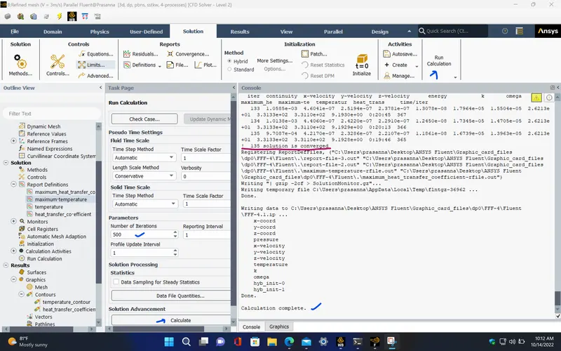
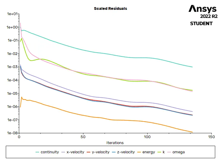
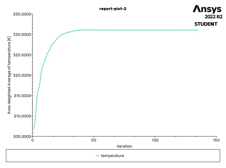
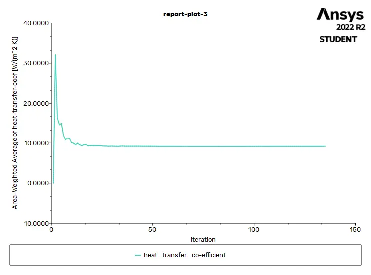
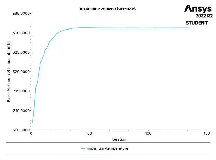
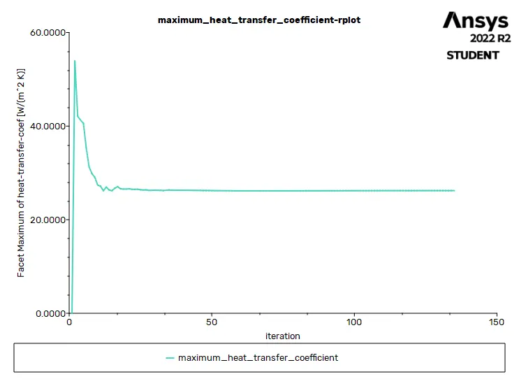
- From the above plots, we see that the solution got converged at 135th iteration since the rate at which residuals, velocity, drag co-efficient and lift co-efficient changes becomes constant over iteration.
Number of iteration - 135
|
Value |
Absolute Criteria |
Convergence Status |
|
|
continuity |
0.000970866 |
0.001 |
Converged |
|
x-velocity |
4.217e-07 |
0.001 |
Converged |
|
y-velocity |
2.328643e-07 |
0.001 |
Converged |
|
z-velocity |
2.210721e-07 |
0.001 |
Converged |
|
energy |
1.186095e-08 |
1e-06 |
Converged |
|
k |
1.673949e-05 |
0.001 |
Converged |
|
omega |
1.396328e-05 |
0.001 |
Converged |
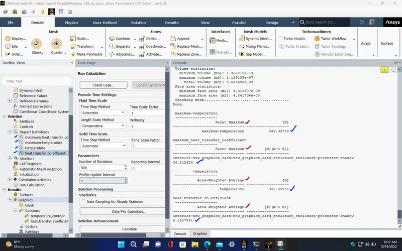
Report definitions :
|
temperature |
331.0973 |
K |
|
heat_transfer_co-efficient |
9.192799 |
W/(m^2 K) |
|
maximum_temperature |
331.32718 |
K |
| maximum_heat_transfer_co-efficient | 26.212624 | W/(m^2 K) |
POST PROCESSING :
TEMPERATURE CONTOUR (Processor) :
HEAT TRANSFER COEFFICIENT CONTOUR (Processor) :
TEMPERATURE CONTOUR (Fins, PCB, Processor) :
TEMPERATURE CONTOUR (XZ plane) :
VELOCITY CONTOUR (XZ plane) :
VELOCITY VECTORS (XZ plane) :
CASE - 3 (Refined mesh, V = 1 m/s) :
- Now, Change the inlet velocity to 1 m/s and repeat the same steps as discussed before.
SETUP AND SOLVING :
- Setup the problem by selecting the required solver and boundary conditions for this simulation. The selected solver models and boundary conditions for running this simulation are as follows,
RESIDUALS PLOT :
AVERAGE TEMPERATURE PLOT (Processor) :
AVERAGE HEAT TRANSFER COEFFICIENT PLOT (Processor) :
MAXIMUM TEMPERATURE PLOT (Processor) :
MAXIMUM HEAT TRANSFER COEFFICIENT PLOT (PROCESSOR) :
Solution status :
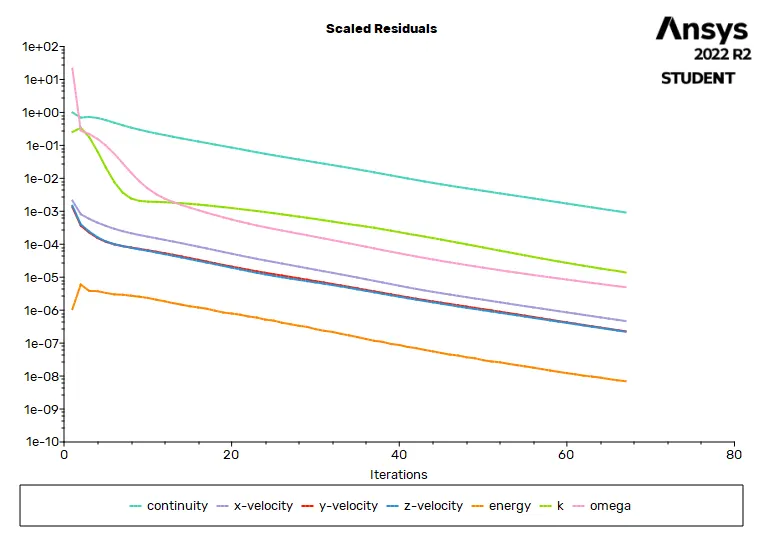
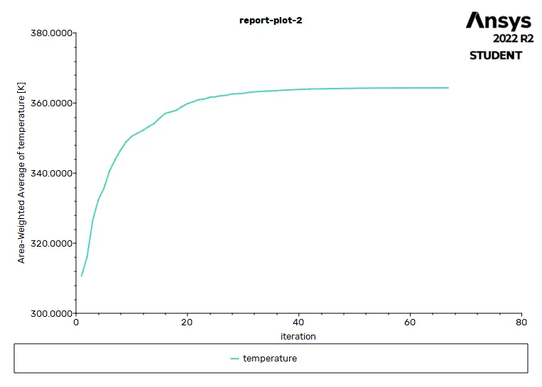
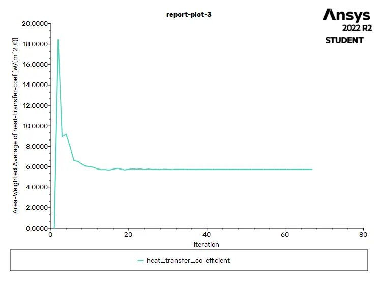
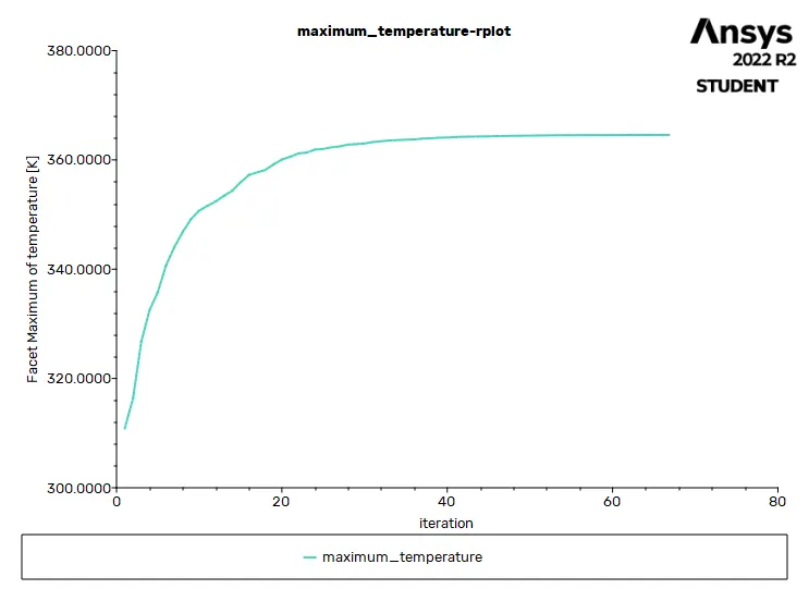
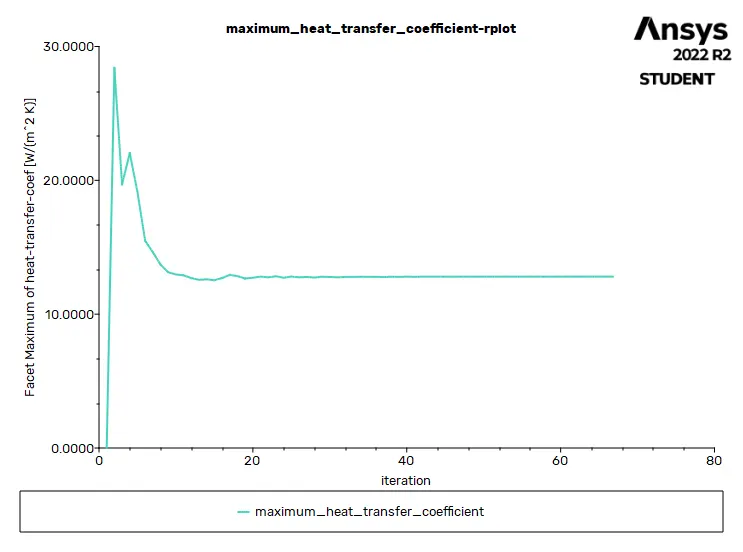
- From the above plots, we see that the solution got converged at 67th iteration since the rate at which residuals, velocity, drag co-efficient and lift co-efficient changes becomes constant over iteration.
Number of iteration - 67
|
Value |
Absolute Criteria |
Convergence Status |
|
|
continuity |
0.0009226624 |
0.001 |
Converged |
|
x-velocity |
4.67117e-07 |
0.001 |
Converged |
|
y-velocity |
2.281747e-07 |
0.001 |
Converged |
|
z-velocity |
2.21585e-07 |
0.001 |
Converged |
|
energy |
6.987759e-09 |
1e-06 |
Converged |
|
k |
1.392127e-05 |
0.001 |
Converged |
|
omega |
4.971202e-06 |
0.001 |
Converged |
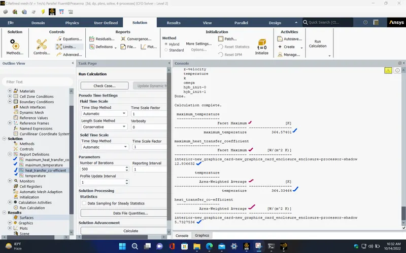
Report definitions :
|
heat_transfer_co-efficient |
5.732754 |
W/(m^2 K) |
|
temperature |
364.3346 |
K |
|
maximum_heat_transfer_co-efficient |
12.8066332 |
W/(m^2 K) |
| maximum_temperature | 364.57401 | K |
POST PROCESSING :
TEMPERATURE CONTOUR (Processor) :
HEAT TRANSFER COEFFICIENT CONTOUR (Processor) :
TEMPERATURE CONTOUR (Fins, PCB, Processor) :
TEMPERATURE CONTOUR (XZ plane) :
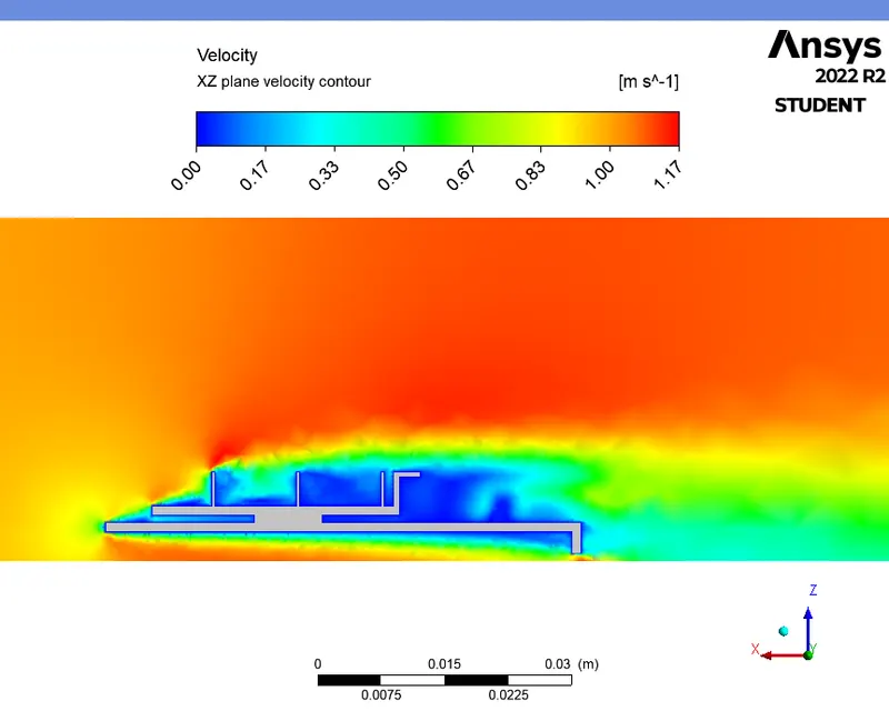
VELOCITY CONTOUR (XZ plane) :
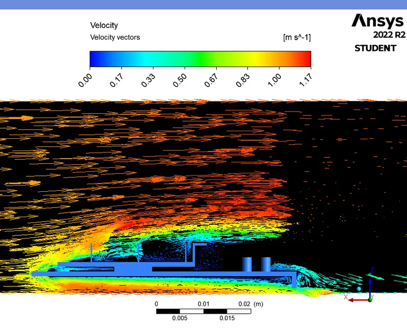
VELOCITY VECTORS (XZ plane) :
CASE - 4 (Refined mesh, V = 5 m/s) :
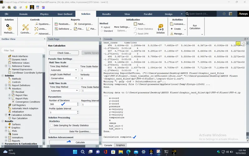
- Here, Change the inlet velocity to 5 m/s and repeat the same steps followed in previous cases.
SETUP AND SOLVING :
- Setup the problem by selecting the required solver and boundary conditions for this simulation. The selected solver models and boundary conditions for running this simulation are as follows,
RESIDUALS PLOT :
AVERAGE TEMPERATURE PLOT (Processor) :
AVERAGE HEAT TRANSFER COEFFICIENT PLOT (Processor) :
MAXIMUM TEMPERATURE PLOT (Processor) :
MAXIMUM HEAT TRANSFER COEFFICIENT PLOT (PROCESSOR) :
Solution status :
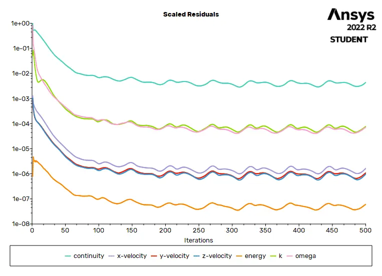
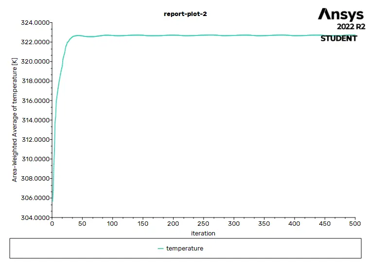
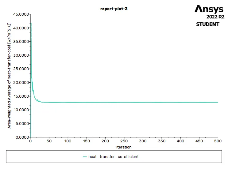
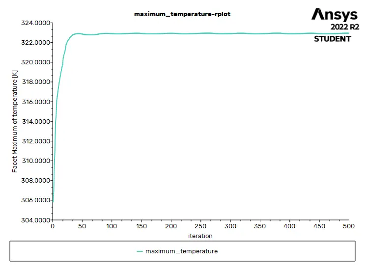
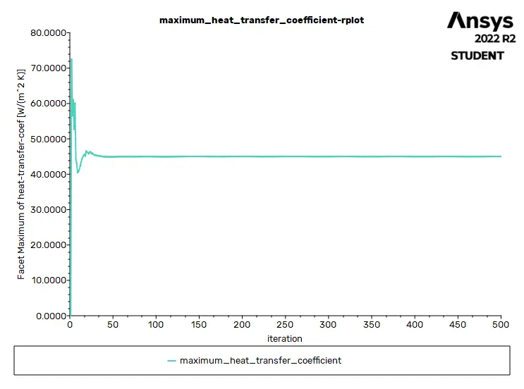
- From the above plots, we see that the solution got converged at 250th iteration since the rate at which residuals, velocity, drag co-efficient and lift co-efficient changes becomes constant over iteration.
Number of iteration - 500
|
Value |
Absolute Criteria |
Convergence Status |
|
|
continuity |
0.004386565 |
0.001 |
Not Converged |
|
x-velocity |
1.637741e-06 |
0.001 |
Converged |
|
y-velocity |
1.084079e-06 |
0.001 |
Converged |
|
z-velocity |
9.705935e-07 |
0.001 |
Converged |
|
energy |
6.0359e-08 |
1e-06 |
Converged |
|
k |
7.711164e-05 |
0.001 |
Converged |
|
omega |
7.114673e-05 |
0.001 |
Converged |
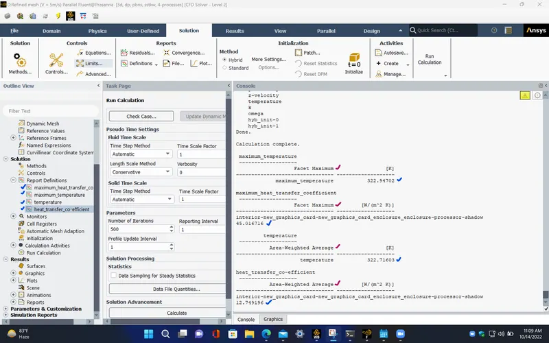
Report definitions :
|
temperature |
322.716 |
K |
|
heat_transfer_co-efficient |
12.7492 |
W/(m^2 K) |
|
maximum_temperature |
322.94702 |
K |
| maximum_heat_transfer_co-efficient | 45.016716 | W/(m^2 K) |
POST PROCESSING :
TEMPERATURE CONTOUR (Processor) :
HEAT TRANSFER COEFFICIENT CONTOUR (Processor) :
TEMPERATURE CONTOUR (Fins, PCB, Processor) :
TEMPERATURE CONTOUR (XZ plane) :
VELOCITY CONTOUR (XZ plane) :
VELOCITY VECTORS (XZ plane) :
RESULTS :
Google drive link for the file,
https://drive.google.com/file/d/1Z_NRMrBJOjPFcRn8sTTmHbSFq2Y4pU4L/view?usp=sharing
|
|
MESH |
VELOCITY OF THE FLUID (Air) (in ‘m/s’) |
AVERAGE TEMPERATURE OF THE PROCESSOR (in ‘K’) |
MAXIMUM TEMPERATURE OF THE PROCESSOR (in ‘K’) |
AVERAGE HEAT TRANSFER COEFFICIENT OVER THE PROCESSOR (in ‘W/m^2-K') |
MAXIMUM HEAT TRANSFER COEFFICIENT OVER THE PROCESSOR (in ‘W/m^2-K') |
||
|
BASE ELEMENT SIZE (in ‘mm’) |
METHOD |
NUMBER OF ELEMENTS
|
||||||
|
CASE 1 |
10.289 (Base line mesh) |
Tetra CFD (Default) |
81383 |
3 |
335.2022 |
335.28809 |
8.564524 |
17.126286 |
|
CASE 2 |
5 (Refined mesh) |
MULTI-ZONE |
452942 |
3 |
331.0973 |
331.32718 |
9.192799 |
26.212624 |
|
CASE 3 |
5 (Refined mesh) |
MULTI-ZONE |
1 |
364.3346 |
364.57401 |
5.732754 |
12.8066332 |
|
|
CASE 4 |
5 (Refined mesh) |
MULTI-ZONE |
5 |
322.716 |
322.94702 |
12.7492 |
45.016716 |
|
CONCLUSION :
- From the above table, we can observe that as we increase the inlet velocity of the air, the convective heat transfer coefficient of the air over the processor increases due to which the temperature of the processor decreases.
- Also we can see that, for the case with 3 m/s inlet velocity, for the different mesh element size, the results are varying between the two cases. Since the refined mesh have the higher number of mesh elements, it gives more accurate results compared to the base line mesh. Although the base line mesh takes less computational time compared to refined mesh case, it doesn't provide accurate results. So, the refined mesh is chosen in order to get the best result for this simulation.
TEMPERATURE CONTOUR (Fins, PCB, Processor) :
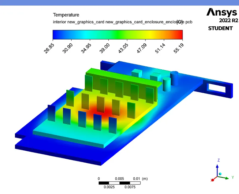
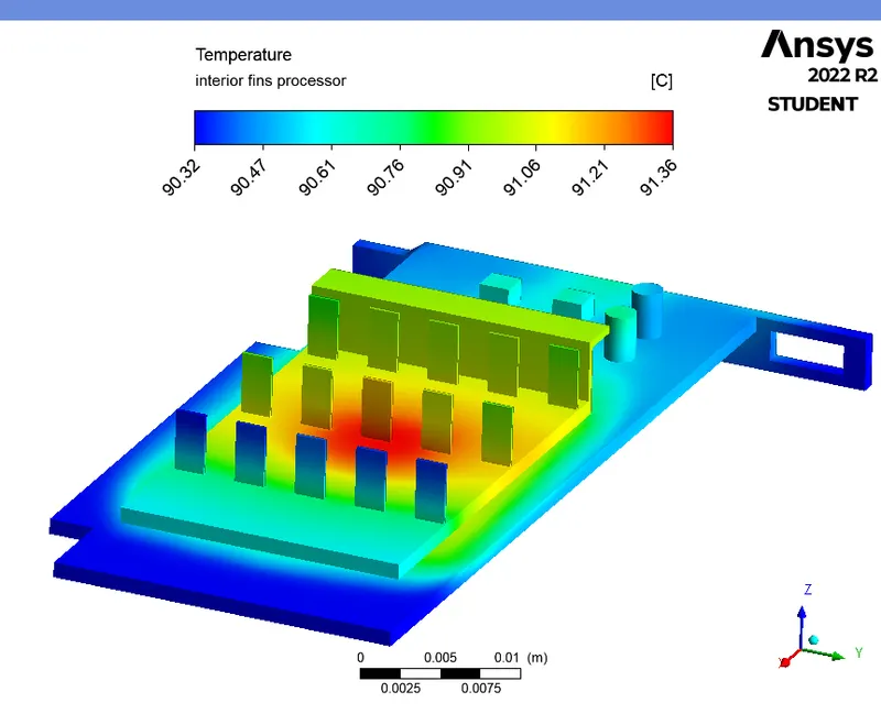
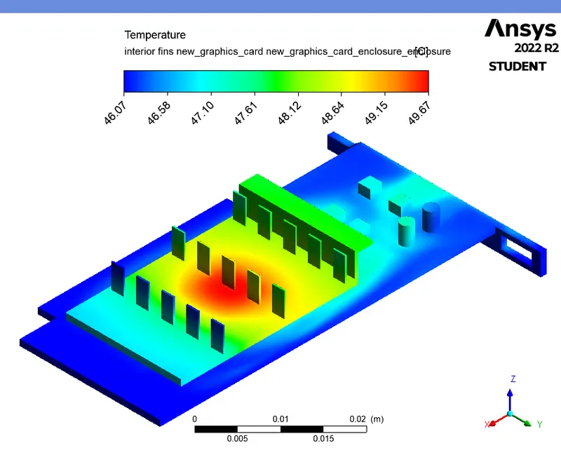
- From the above contour, we can see that the temperature maximum at the centre portion of the fins region. This is because, the processor is the heat source from which the heat is generated and then transferred, to the surrounding air by means of convection, and to the fins by means of conduction.
TEMPERATURE CONTOUR (Processor) :
HEAT TRANSFER COEFFICIENT CONTOUR (Processor) :
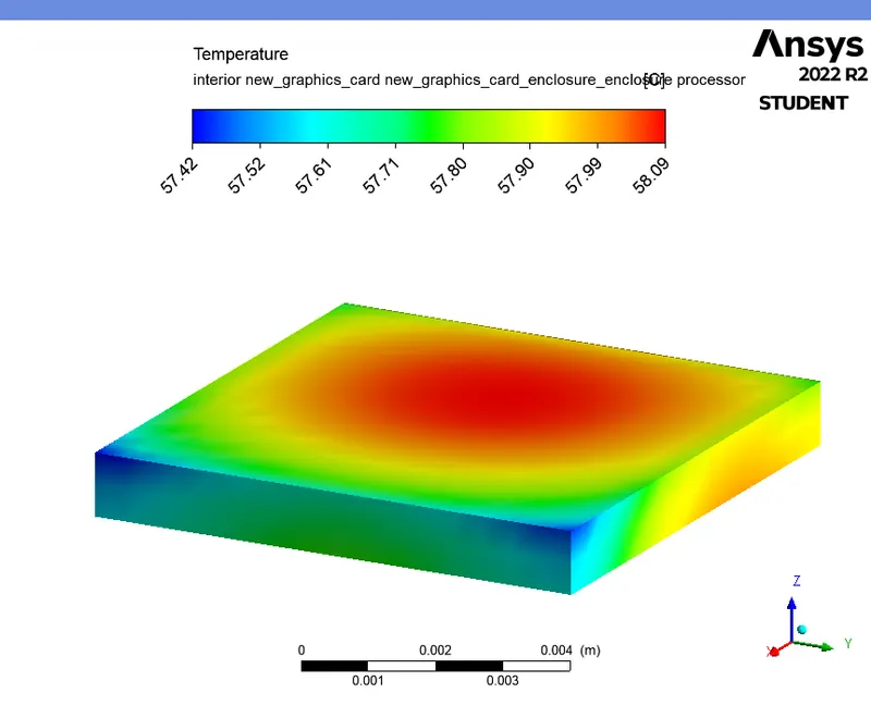
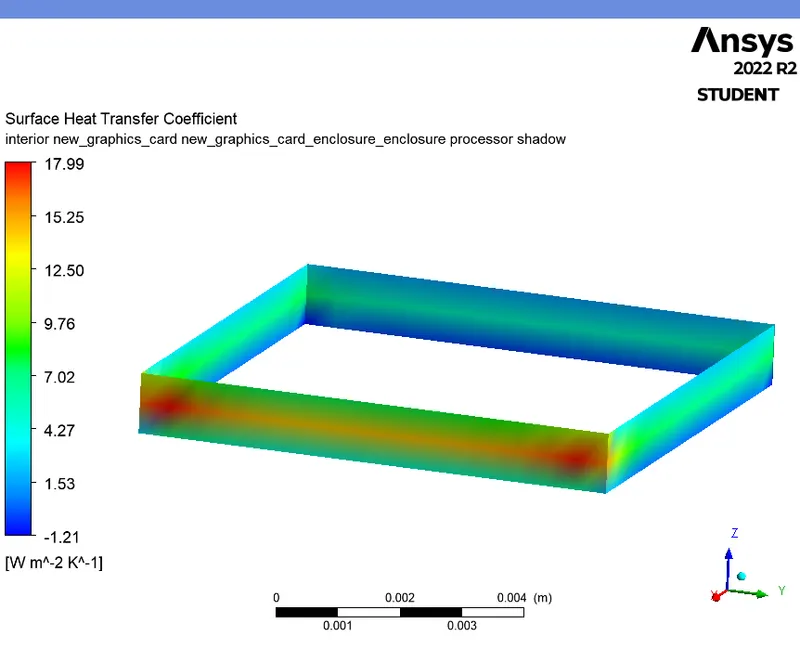
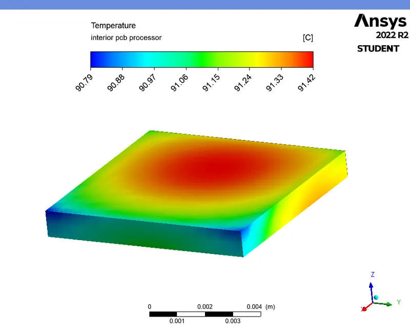
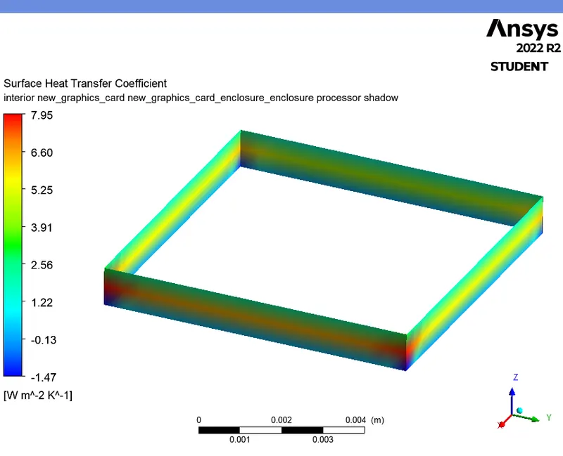
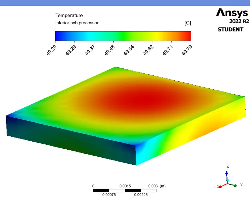
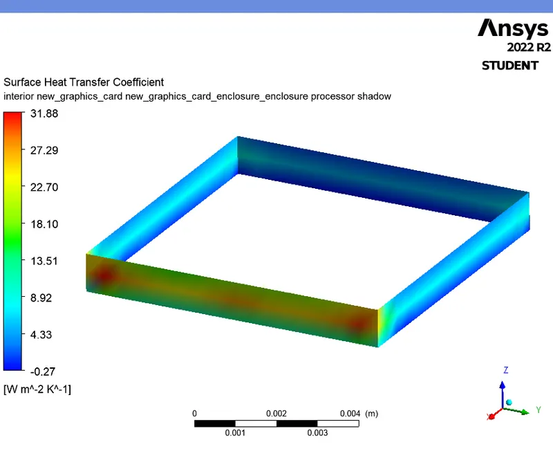
- From the temperature contour of the processor, we can see that, the temperature is lower(compared to other regions) at the front rectangular surface and mostly, at the front surface corners of the processor which is perpendicular to the air flow. This is due to the higher heat transfer coefficient of air near to that surface (Refer the above heat transfer coefficient contour of the processor). Since the air is directly flowing over that regions which causes higher bulk motion of air (convection) over that region compared to others, most of the heat is transferred from the that region to the air. Hence, the temperature at that region is reduced.