pV diagram of the otto cycle
AIM:
To create a pV diagram of otto cycle and to calculate its thermal efficiency.
MAIN PROGRAM:
% To create a PV diagram of Otto cycle.

clear all
close all
clc

% input values
% gamma = Cp/Cv and for air, gamma = 1.4
gamma = 1.4;
% Temperature at the end of heat addition process(i.e, at point 3)
% (in 'K')
t3 = 2300;

% Engine geometric parameters

% Diameter of the engine cylinder(in 'm')
bore = 0.1;
% Stroke length of the engine cylinder(in 'm')
stroke = 0.1;
% Length of the Connecting rod(in 'm')
con_rod = 0.15;
% Compression ratio = v1/v2
cr = 12;

% STATE VARIABLES OF POINT 1 (at the start of compression process)

% Pressure of the air at the start of compression process
p1 = 101325;
% Temperature of the air at the start of compression process
t1 = 500;

% Formula used to calculate swept volume
v_swept = (pi/4)*bore^2*stroke;

% Formula used to calculate clearance volume
v_clearance = v_swept/(cr-1);

% Initial volume of the air before compression
v1 = v_swept + v_clearance;

% Volume at end of the compression process
v2 = v_clearance;

% STATE VARIABLES OF POINT 2 (at the end of compression process)

% Pressure of the air at the end of compression process
p2 = p1*(cr^gamma);
% Temperature of the air at the end of compression process
t2 = p2*t1/(cr*p1);

% To calculate the constant'c' for the isentropic process during compression
constant_c = p1*(v1^gamma);

% Volume trace during compression is found by using engine kinematics
% The funtion 'engine_kinematics' is called below
V_compression = engine_kinematics(bore,stroke,con_rod,cr,180,0);

% Pressure trace during isentropic compression is found by the relation
P_compression = constant_c./(V_compression.^gamma);

% STATE VARIABLES OF POINT 3 (at the start of expansion process)

% Since the heat addition is done at constant volume
% Volume at the end of heat addition is given by
v3 = v2;

% Pressure of the air at the start of expansion process
p3 = (p2*t3)/t2;

% To calculate the constant'c1' for the isentropic process during expansion
constant_c1 = p3*(v3^gamma);

% Volume trace during expansion is found by using engine kinematics
% The funtion 'engine_kinematics' is called below
V_expansion = engine_kinematics(bore,stroke,con_rod,cr,0,180);

% Pressure trace during isentropic expansion is found by the relation
P_expansion = constant_c1./(V_expansion.^gamma);

% STATE VARIABLES OF POINT 4 (at the end of expansion process)

% Since the heat rejection is done at constant volume
% Volume at the end of expansion is given by
v4 = v1 ;

% Pressure of the air at the end of expansion process
p4 = p3*(v3/v4)^gamma;

% Temperature of the air at the end of expansion process
t4 = p4*t3*v4/(v3*p3);

% THERMAL EFFICIENCY OF THIS OTTO CYCLE is calculated by

therm_eff = (1-(1/(cr^(gamma-1))))*100 % percentage

% Plotting

hold on

xlabel('Volume')
ylabel('Pressure')

plot(v1,p1,'*','Color','k')
plot(v2,p2,'*','Color','k')
plot(v3,p3,'*','Color','k')
plot(v4,p4,'*','Color','k')

plot(V_compression,P_compression,'Color','b')

plot([v2 v3],[p2 p3],'Color','r')

plot(V_expansion,P_expansion,'Color','b')

plot([v4 v1],[p4 p1],'Color','r')
SUPPLEMENTARY PROGRAM:
To calculate the volume trace during compression and expansion process, using engine kinematics, the below FUNCTION is used in the main program.
% To calculate the engine kinematics

function [V] = engine_kinematics(bore,stroke,con_rod,cr,start_crank,end_crank)

% Crank pin radius is given by
a = stroke/2;
% Ratio of connecting rod length to the crank pin radius
R = con_rod/a;

% Swept volume
v_s = (pi/4)*bore^2*stroke;
% Clearance volume
v_c = v_s/(cr-1);

% Various crank angles
theta = linspace(start_crank,end_crank,100);

% To calculate the volume trace 'V'
term1 = 0.5*(cr-1);
term2 = R + 1 - cosd(theta);
term3 = (R^2 - (sind(theta)).^2).^0.5;

V = (1 + term1*(term2 - term3)).*v_c;

end
OUPUT PLOT :
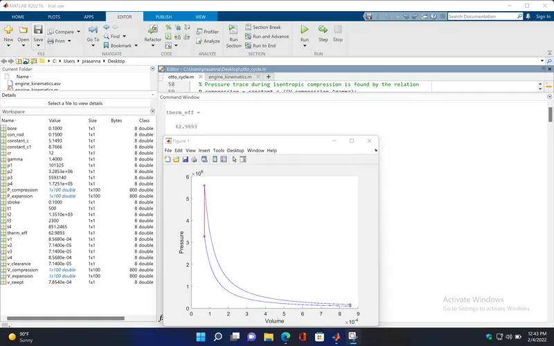
The Thermal efficiency of this engine is 63%
EXPLANATION:
The otto cycle is an air standard cycle (Air is the working fluid) which consists of four processes, two reversible adiabatic compression and expansion , and two constant volume heat addition and heat rejection.
In pV diagram,
- Process 1-2, Isentropic compression (also Reversible adiabatic process).
In this process, the air is compressed isentropically (i.e, at constant entropy).This process is a reversible adiabatic process.
- Process 2-3, Constant volume heat addition.
In this process, heat is added to the air by keeping the volume constant.
- Process 3-4, Isentropic expansion(also Reversible adiabatic process).
In this process, the air expands isentropically (i.e, at constant entropy).This process is a reversible adiabatic process.
- Process 4-1, Constant volume heat rejection.
In this process, heat is rejected by keeping the volume constant.
FORMULA USED:
From the engine kinematics,
- `V/V_c = 1 + 1/2*(CR - 1)*[R+1- cos(theta)-(R^2 - sin^2(theta))^0.5]`
- `a = l_s/2`
- `R = l_c/a`
For Isentropic process , the relation between P, V and T is given by,
- `P*V^gamma = constant`
For the state points 1 and 2,
- `P_1*V_1^gamma = P_2*V_2^gamma`
For the state points 3 and 4,
- `P_3*V_3^gamma = P_4*V_4^gamma`
From the ideal gas equation,
For the state points 1 and 2,
- `(P_1*V_1)/T_1 = (P_2*V_2)/T_2`
For the state points 2 and 3,
- `P_2/T_2 = P_3/T_3` (since V_2 = V_3)
To calculate V_1 and V_2,
- `V_s = (pi/4)*d^2*l_s`
- `V_c = V_s /(CR - 1)`
- `V_1 = V_s + V_c`
- `V_2 = V_c`
Thermal Efficiency of a otto cycle,
- `eta_t = 1 - (1/(CR^(gamma-1)))`
Where,
P_1,P_2,P_3,P_4 - Pressure of the air at the state points 1,2,3 & 4, N/m^2
T_1,T_2,T_3,T_4 - Temperature of the air at the state points 1,2,3 & 4, K
V_1,V_2,V_3,V_4 - Volume of the air at the state points 1,2,3 & 4, m^3
V_s - swept volume, m^3
V_c - Clearance volume, m^3
V - Volume trace, m^3
CR - Compression ratio ( V_1/V_2)
l_s - Stroke length, m
l_c - Connecting rod length, m
theta - crank angle, in degrees
d - Diameter of the engine cylinder, m
ERRORS OCCURED DURING THE PROGRAM:
The bore and stroke variables are not entered,
function [V] = engine_kinematics(con_rod,cr,start_crank,end_crank)
In the function script, I have missed to enter the bore and stroke variables in the function definition. so, the clearance volume (v_c) is not calculated which is used to find the volume trace during compression and expansion process, the V_compression and V_expansion is not calculated and so the curve is not formed in pV diagram.
Now, the bore and stroke variables are entered,
function [V] = engine_kinematics(bore,stroke,con_rod,cr,start_crank,end_crank)