Week 6 - CHT Analysis on a Graphics card
Notice: - After the analysis, the size of the file is more, but in the challenge submission time it is not supported because of its large so I am sharing the google drive link please download from the link.
Link: https://drive.google.com/file/d/1DIbEc5kpXZtYpQ7BarwO5naHA-tSy-J2/view?usp=drivesdk
Aim
Perform a steady-state conjugate heat transfer analysis on a model of a graphics card. We have to use appropriate materials for the simulation and run the simulation for best possible mesh with combination of course and refined mesh in different regions with different boundary condition.
Conjugate heat transfer (CHT)
The Conjugate Heat Transfer (CHT) analysis type permits the simulation of heat transfer between solid and fluid domains by transferring thermal energy at their interfaces. Examples of typical applications for this analysis type include the simulation of heat exchangers, the cooling of electronic devices, and all-purpose cooling and heating systems. Due to coupling, which necessitates a significant number of parameters to characterise both the fluid and solid domains, such heat transfer devices are challenging to develop and construct. By modelling each domain separately, the problem is decoupled. The models from the two domains are then combined using the continuity criteria at the solid/fluid interface, which are:
- Continuity of temperature field
- Continuity of heat flux
Application of CHT
Convection is a complicated phenomenon that involves the transfer of energy between an object and its surroundings. It is caused by a fluid stream close to an item's surface that is not the same temperature as the fluid bulk. Thus, the phenomenon has both a local and a global component. Fluid entering the object close to it is contaminated by exchanges that have previously happened along the boundary at various points, giving the exchange both a global and a local character depending on the state of the object locally at any given point. Heat transfer that is conjugate occurs when convection and conduction happen at the same time.
Solving and modelling approach
In the modelling and solving approach we follow some steps these are
- Geometry modelling
- Meshing
- Steps for solving
- Calculation
- Result
Geometry modelling
The model of graphics card is made up of some parts which are made up of different materials like base, processer and fin. In the graphics card one encloser is added which named as inlet, outlet and symmetry wall.
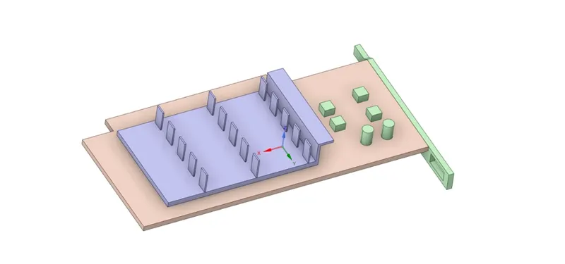
(Graphics card)
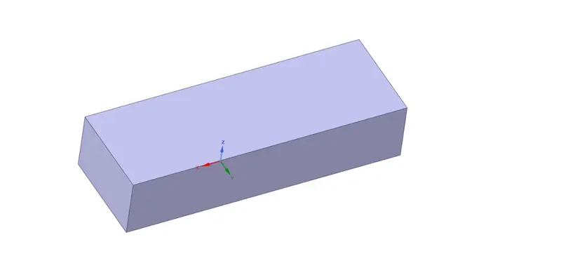
(Graphics card with encloser)
Meshing
In the meshing case we consider two cases in first cases we take coarse mesh and, in another mesh. When the mesh size is different the result will different.
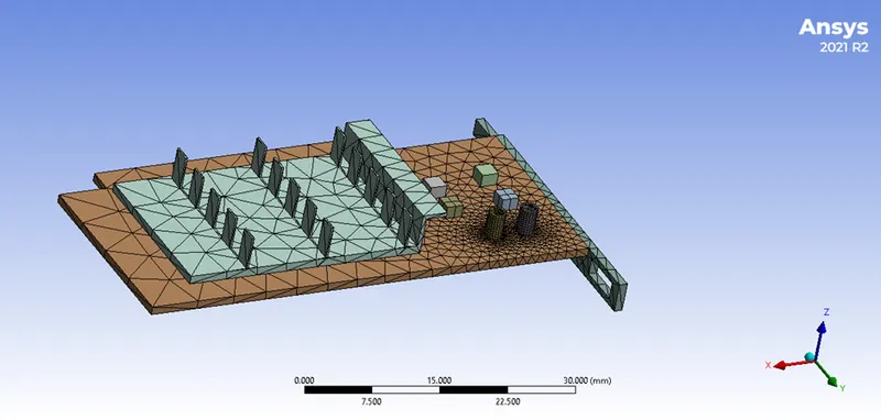
(Coarse mesh)
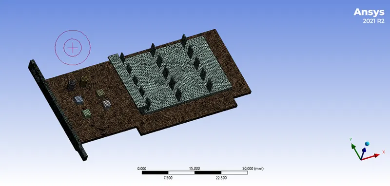
(Fine mesh)
In the fine mesh we take the sizes are
Element size: 0.005m
Body size (Fin):0.0005m
Body size (Processer):0.0005m
Body size (Base): 0.003m
The curvature capture is yes for all the sizes
Steps for solving
In our solving process we have to assign the material which we are applying three materials for solving process. We are assigning 3 materials for three components. These components and their properties are
- Aluminium (For Fin material)
Density: 2719 kg/m^3
Specific heat: 871 j/kg-K
Thermal conductivity: 202.4 w/m-K
- Silicon (For processer material)
Density: 2330 kg/m^3
Specific heat: 712 j/kg-K
Thermal conductivity: 148 w/m-K
- A composite material taking as FR-4 (For base material)
Density: 1850 kg/m^3
Specific heat: 1300 j/kg-K
Thermal conductivity: 0.27 w/m-K
The encloser is use Air as fluid material
In the processer the silicon material is generating heat which has to cool.
Graphics card power = 1W
Volume of the card = 8*8*1= 64e-9 m^3
Heat generated = Graphics card power/volume of graphics card
= 1/64e-9= 1.5625e+7 w/m^3
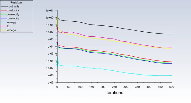
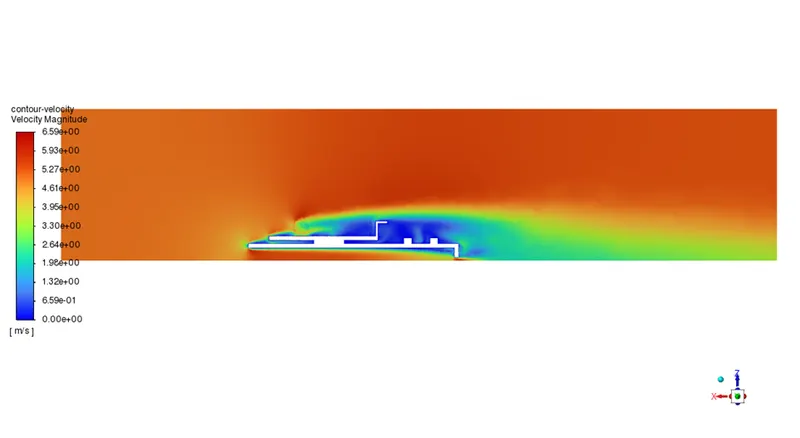
We use the pressure-based study state solver, in the boundary condition we use 5m/s velocity for inlet air for coarse mesh and for fin mesh we use three different velocities 1m/s, 3m/s and 5m/s. Use hybrid initialization and calculate.
Result
In the result we tale two cases one for coarse mesh size and another one for fine mesh.
Case-1
In this case we take coarse mesh and the boundary condition as 5m/s inlet velocity, temperature 300K and processer generating 1.5625e+7 w/m^3.
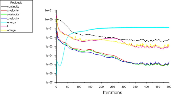
(Residuals)
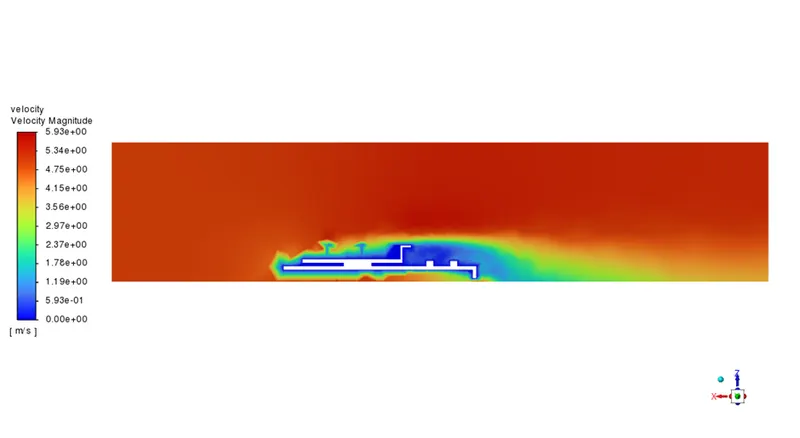
(Velocity contour)
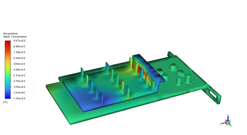
(Temperature contour)
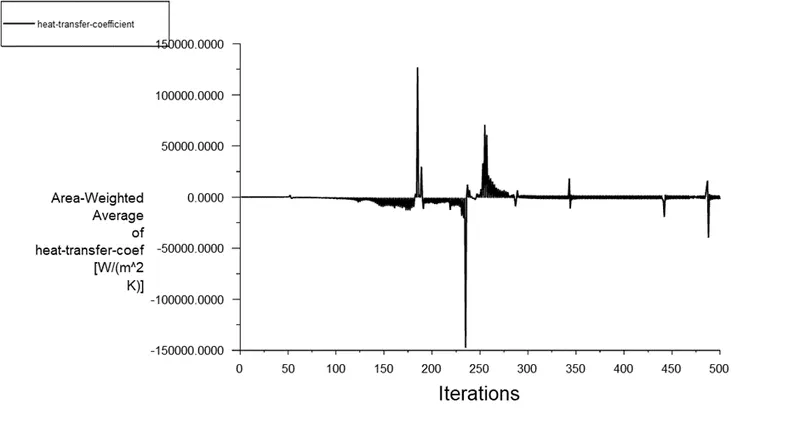
(Heat transfer coefficient)
In this case the result plotted is not correct, in the temperature contour less heat is transferred to the air and colling process is very slow. Now we can use fine mesh and check the results.
Case-2
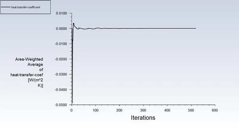
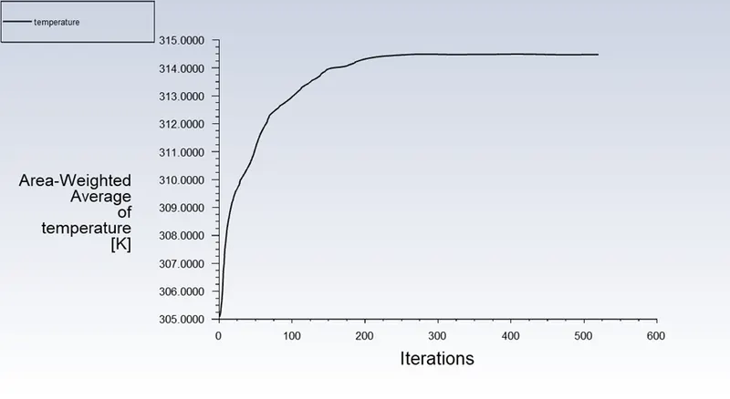
In the case-2 we use same heat generated processer and temperature of air 300k and specific heat transfer coefficient is 20w/m^2K. in this case we use three different velocity conditions and plot the results below
For 1m/s velocity inlet
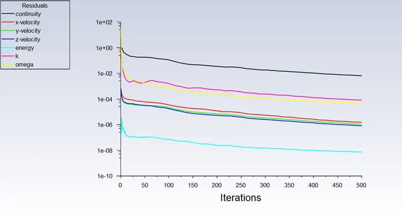
(Residuals)
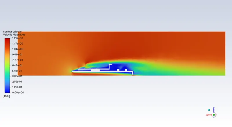
(Velocity contour)
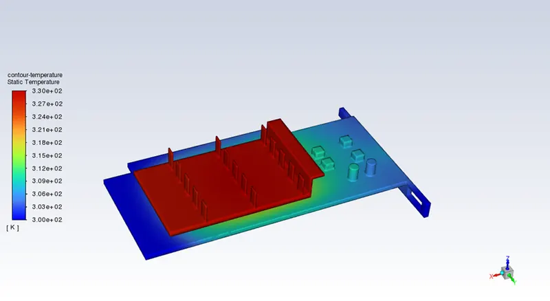
(Temperature contour)
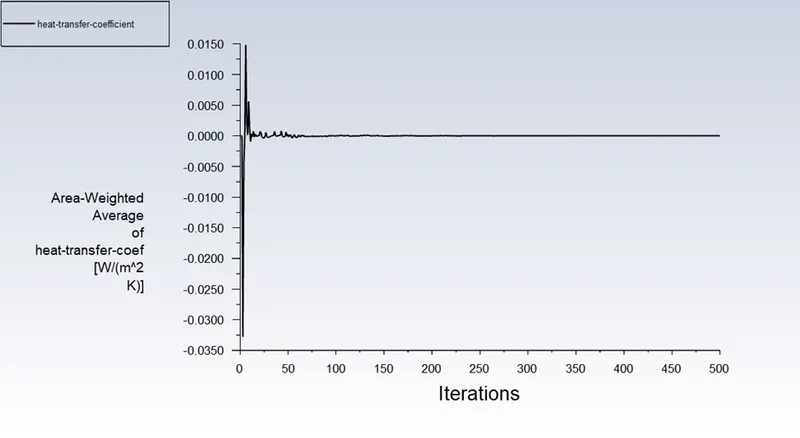
(Heat transfer coefficient of processor)
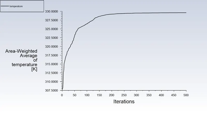
(Average temperature of processor)
For 3m/s velocity inlet
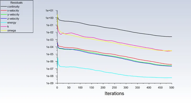
(Residuals)
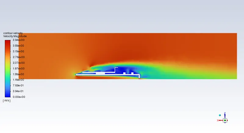
(Velocity contour)
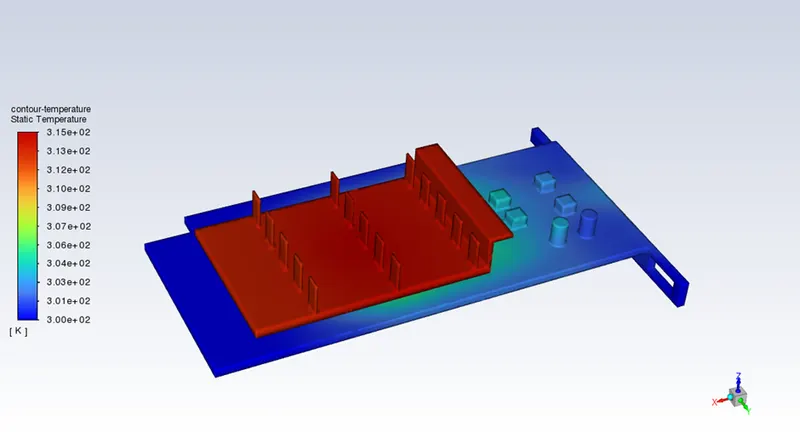
(Temperature contour)
(Heat transfer coefficient of processor)
(Average temperature of processor)
For 5m/s inlet velocity
(Residuals)
(Velocity contour)
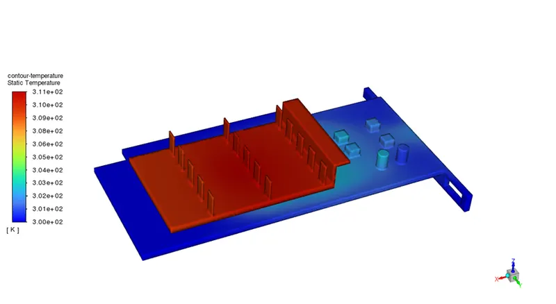
(Temperature contour)
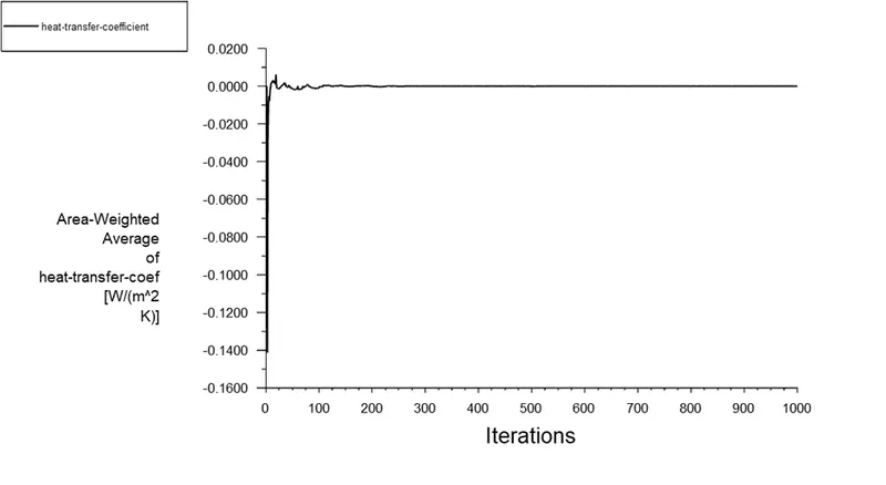
(Heat transfer coefficient of processor)
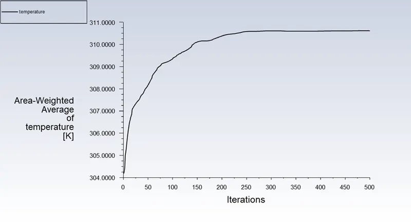
(Average temperature of processor)
|
Sl No. |
Inlet velocity (m/s) |
Temperature at processer (K) |
Heat transfer coefficient at processer (w/m^2-K) |
|
1 |
1 |
329.599 |
1.3632e-06 |
|
2 |
3 |
314.477 |
1.3642e-06 |
|
3 |
5 |
310.61 |
-1.6545e-05 |
From the plotted results we can see that the heat transfer of the processer the more when the velocity of the air is more so the temperature of the processer is less. When the velocity decreases the temperature of the processer is more.
Conclusion
When the number of elements is increases the accuracy of the of the result is increases. It is apparent from the preceding data that as inlet velocity increases, the net temperature of graphics card components falls. As a result, it can be concluded that a higher inlet velocity leads to better cooling and a lower average temperature, protecting the components from harm.
Furthermore, it is evident that components' temperatures rise as inflow velocity drops from 5 m/s to 1 m/s, further demonstrating that higher velocity improves cooling.
In the conjugate heat transfer the is depends upon the velocity and temperature of air.