Week 6 - CHT Analysis on a Graphics card
AIM:
To perform a steady state conjugate heat transfer analysis on graphics card.
OBJECTIVE:
- To run the simulation at three different velocity of air.
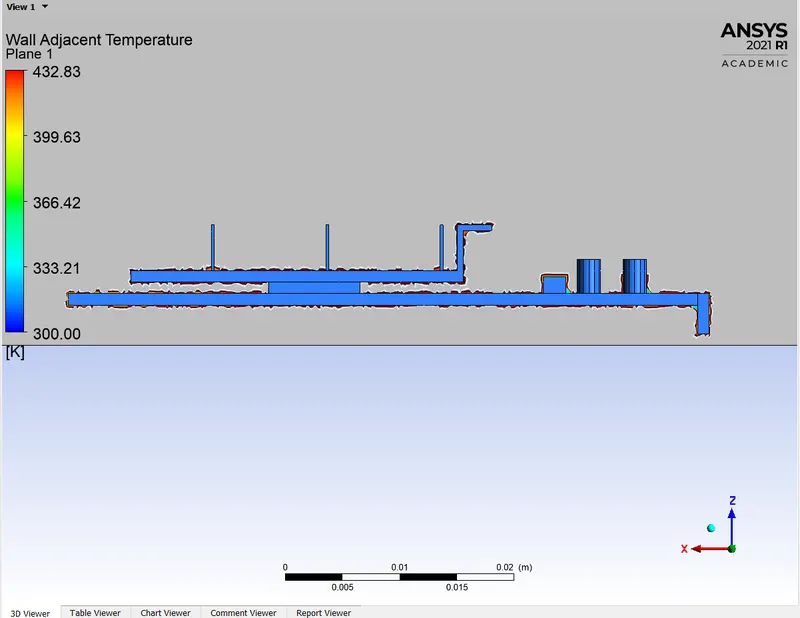
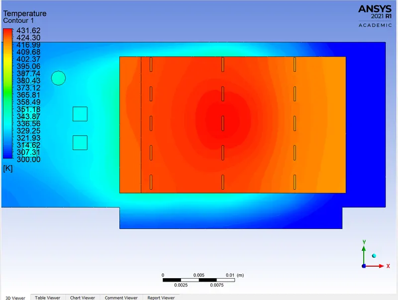
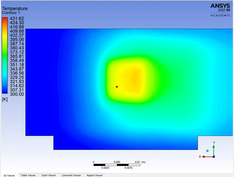
- To identify the potential hotspot in the graphics card.
INTRODUCTION:
GRAPHICS CARD:
A graphics card is an expansion card which generates a feed of output images to a display device. A computer’s CPU works by either enabling signals to pass through its microscopic transistors or by blocking them. As electricity passes through the CPU or gets blocked inside, it get turned into heat energy. While a processor in a high performance workstation may run hot due to heavy use, a processor in a regular computer that overheats is almost always a sign of a malfunctioning system.
Computer cooling is required to remove the waste heat produced by computer components to keep components with permissible operating temperature limits. Components that are susceptible to temporary malfunction or permanent failure if overheated include integrated circuits such as central processing units, chipsets, graphics cards and hard disk drives.
CONJUGATE HEAT TRANSFER:
Conjugate heat transfer is a process that involves the variation of temperature within solid and fluid due to thermal interaction between them. CHT analysis allows the simulation of the heat transfer between solid and fluid domains by exchanging thermal energy at the interfaces between them. CHT analysis is advantageous in accurately simulating the surface temperature and heat exchanging capabilities of various devices and engineering machines.
APPLICATIONS:
CHT analysis helps to understand the effectiveness of various thermal systems involving solid and fluid medium. It helps to simulate and understand thermal systems like heat sinks, coolers, heat exchangers, exhaust port of vehicles, internal combustion engines, boilers, HVAC, Electronic components cooling etc..
PROCEDURE:
GEOMETRY:
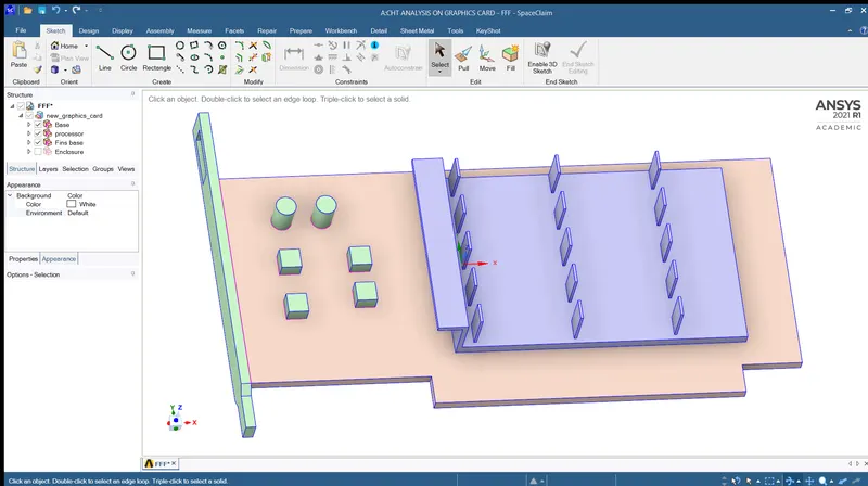
- The geometry is imported into the spaceclaim in the format that spaceclaim can read.
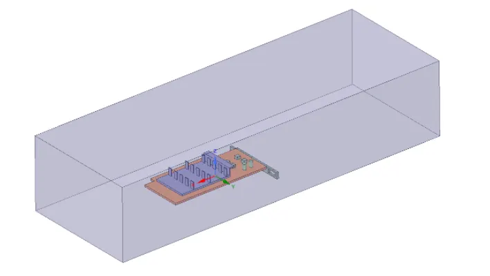
- To perform a CHT analysis on graphics card an enclosure is created around the graphics card. Air will be used as cooling fluid.
- The graphics card contains three main components. A fins, processor and a base.
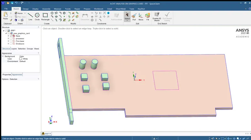
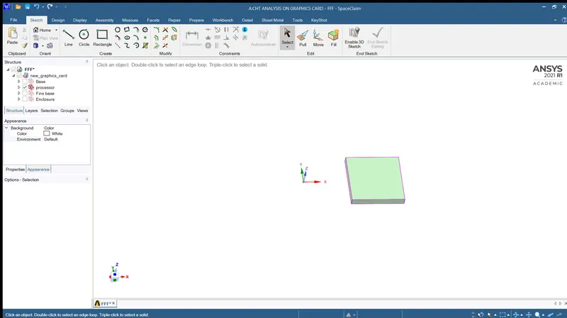
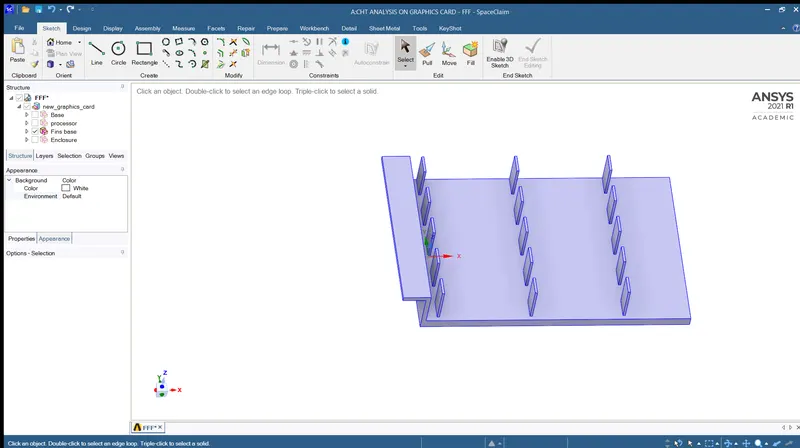
- The base and the fins will conduct the heat away from the processor and that heat will be carried away by cooling air through forced convection.
- The share topology is enabled to generate a conformal mesh.
MESHING:
- Before generating the mesh we have to create the named selections. The named selection are inlet, outlet, symmetry wall for outer enclosure, pcb board, processor and fins.
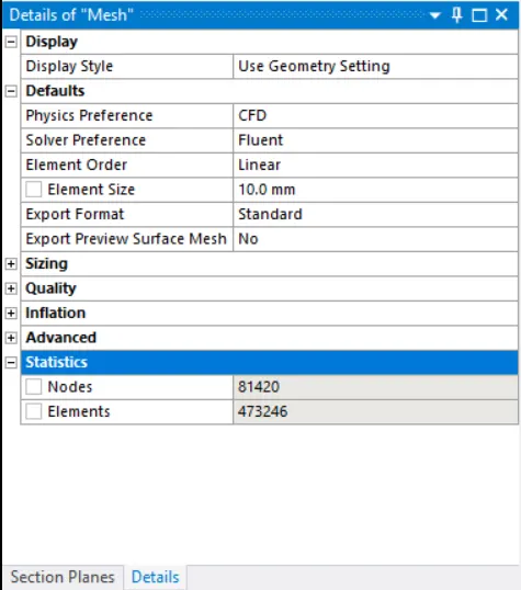
- Element size for enclosure – 10mm
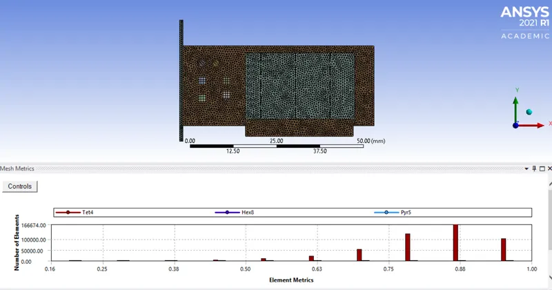
- Mesh metrices – element quality
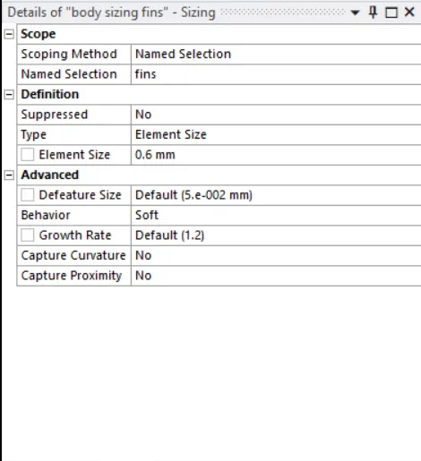
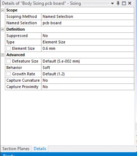
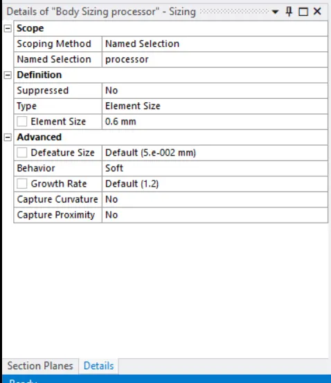
- Body sizing for fin, processor and pcb board – 0.6mm
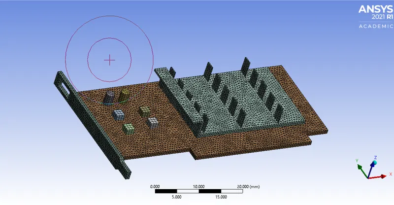
- No of nodes – 81420
- No of elements – 473246
Final meshed model:
SETUP:
GENERAL:
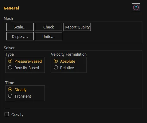
- Type - Pressure based
- Velocity formulation – absolute
- Time – steady
MODEL:
- Energy – on
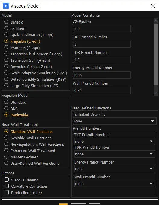
- Viscous – realizable k-epsilon with standard wall function
MATERIAL:
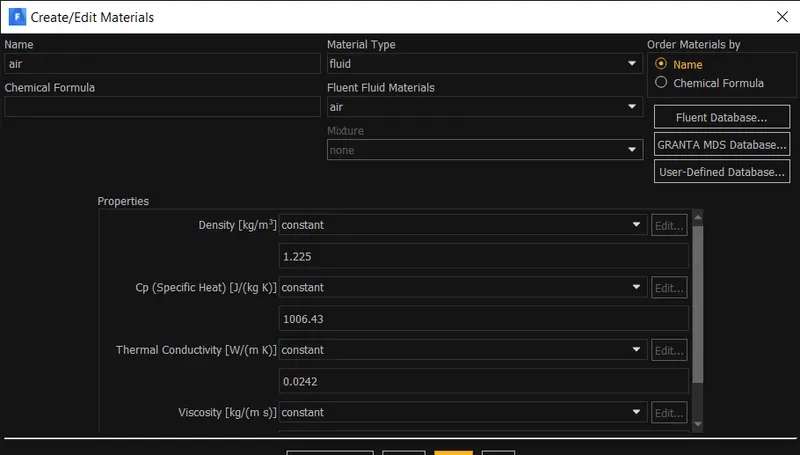
- Fluid – air
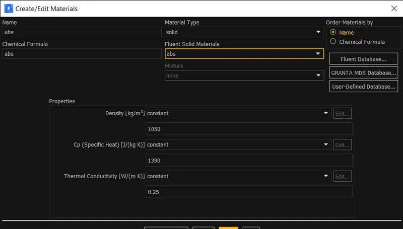
- Solid – Base – ABS (Acrylonitrile butadiene styrene)
Processor – silicon
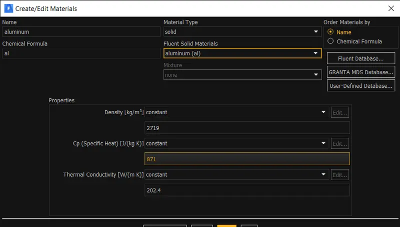
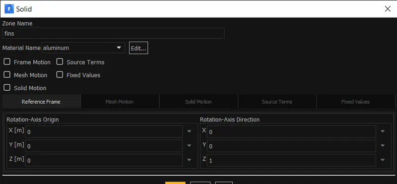
Fins – aluminium
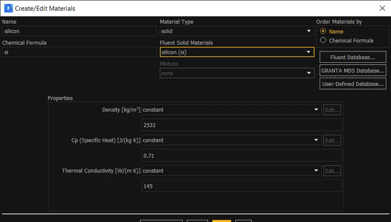
CELL ZONE:
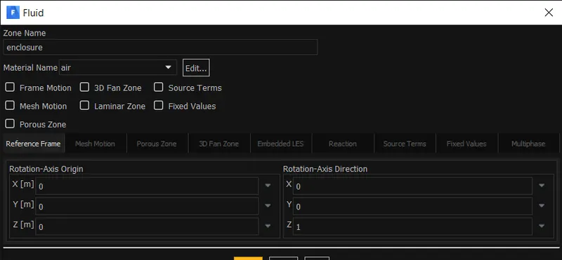
- Enclosure: fluid – air
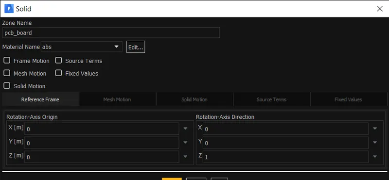
- Graphics card base: solid – ABS
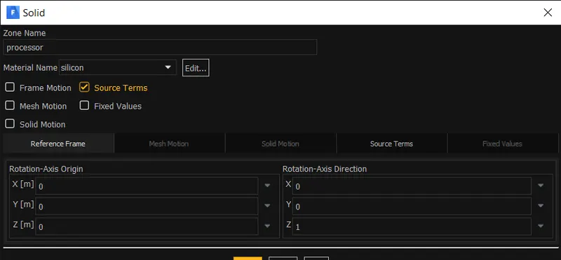
- Graphics card processor: solid – silicon
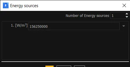
Source from processor – 156250000 w/m3
- Graphics card fins: solid – aluminium
BOUNDARY:
INLET:
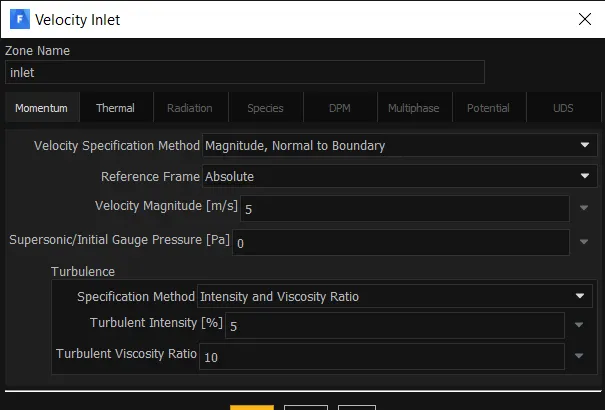
- Velocity – Case 1 – 1m/s
Case 2 – 3m/s
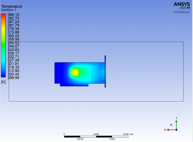
Case 3 – 5m/s
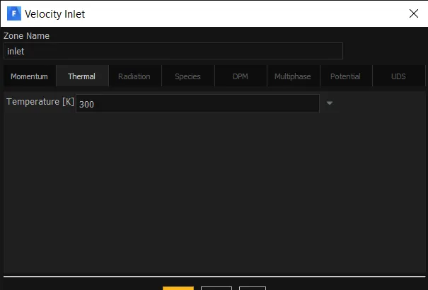
- Temperature – 300k
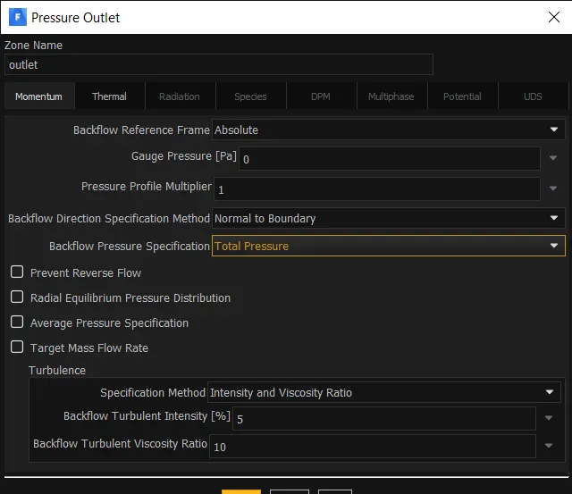
OUTLET:
Gauge pressure - zero
SYMMETRY WALL:

OTHER BOUNDARY:
Walls and interior type
INITIALIZATION:
Hybrid initialization

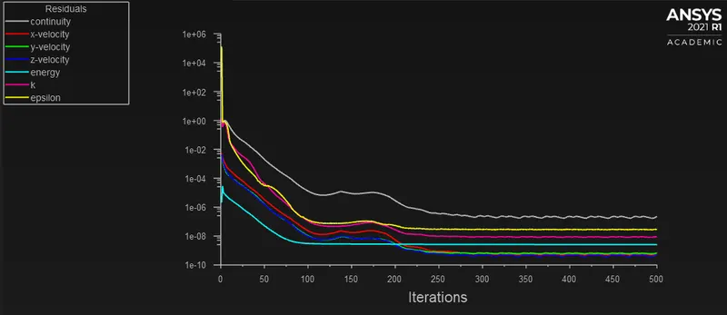
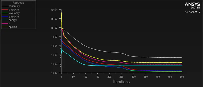
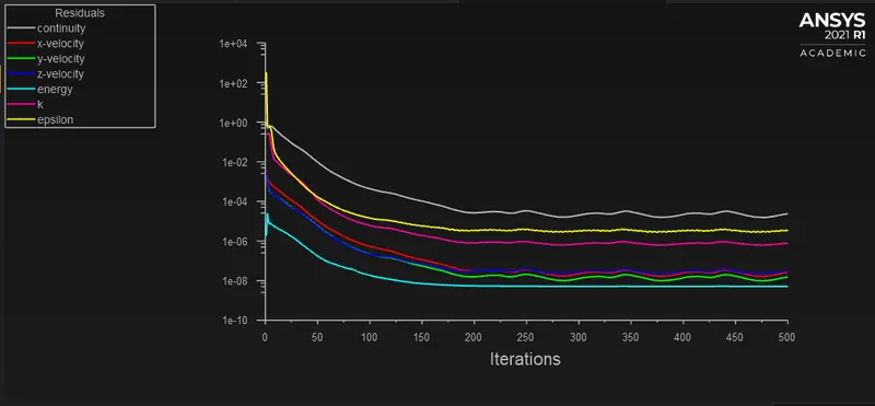
The simulation is runned for 500 iterations.
RESULTS:
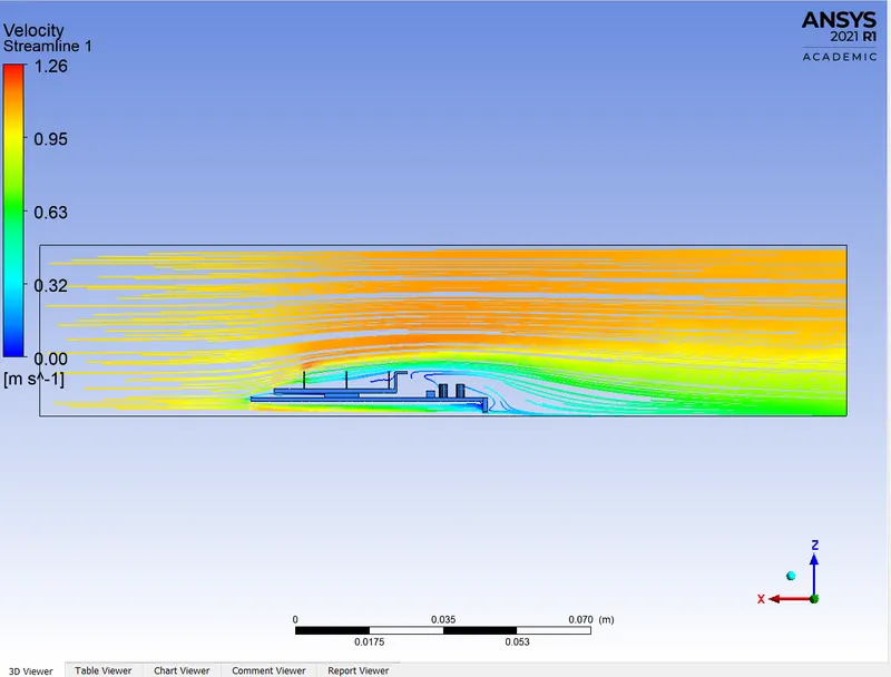
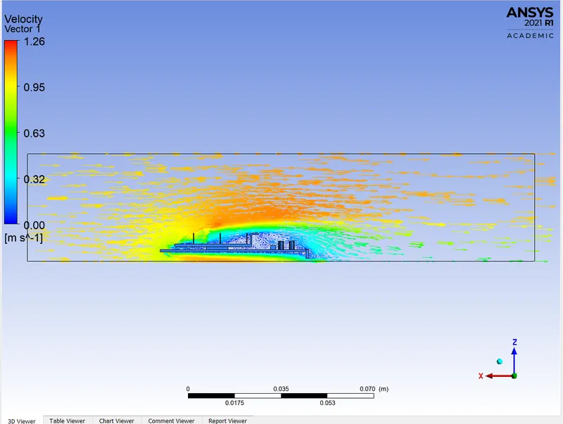
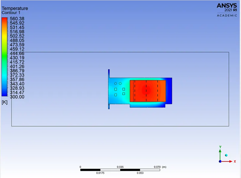
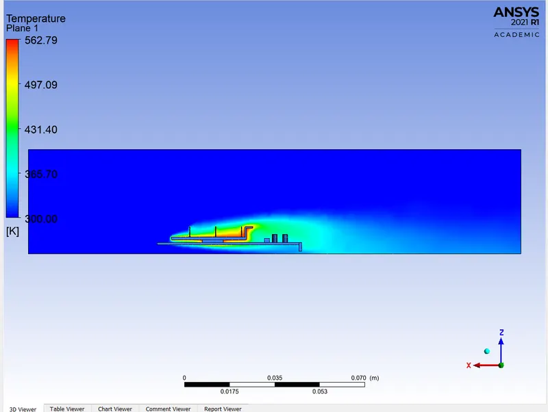
FOR CASE 1 – VELOCITY = 1M/S
RESIDUAL:
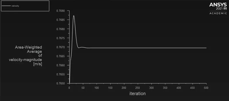
VELOCITY PROFILE:
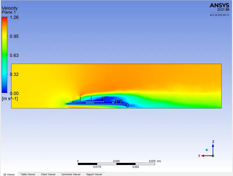
VELOCITY CONTOUR:
VELOCITY STREAMLINE:
VELOCITY VECTOR:
TEMPERATURE CONTOUR:
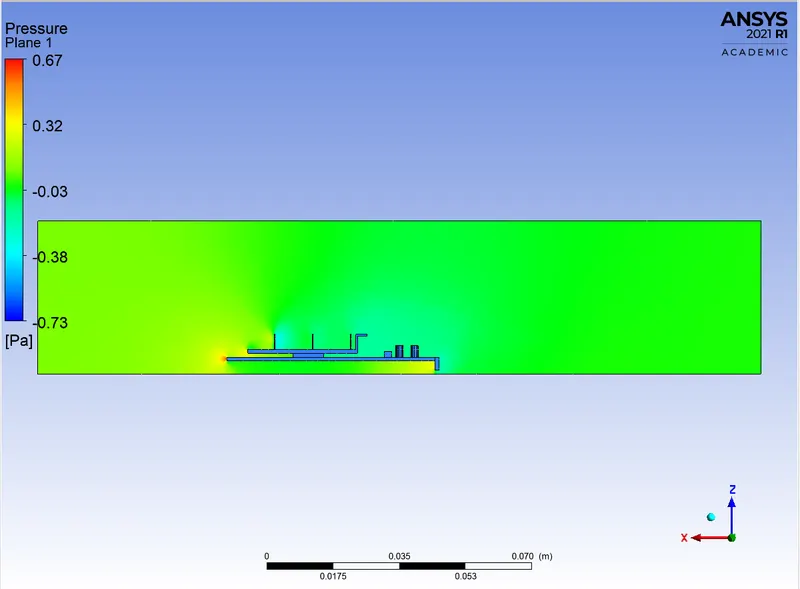
PRESSURE CONTOUR:
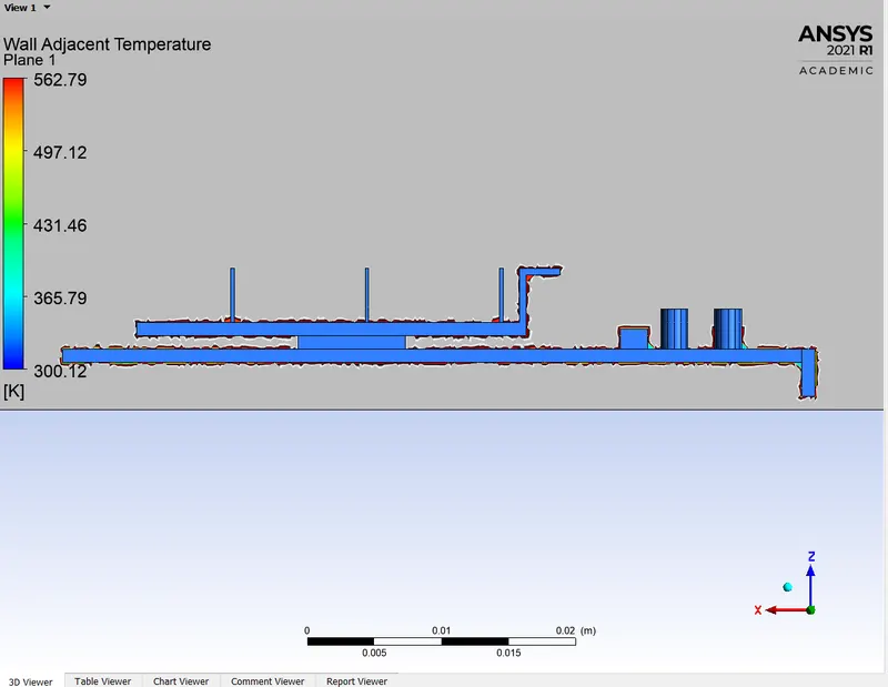
WALL ADJACENT TEMPERATURE:
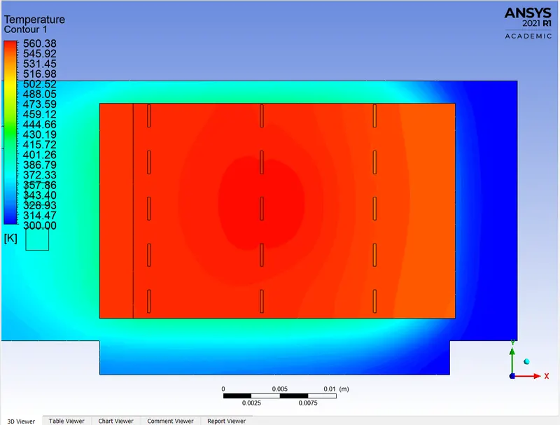
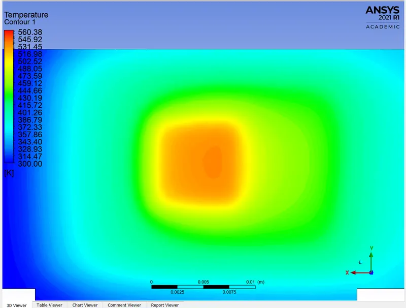
HOTSPOTS:
FOR CASE 2 – VELOCITY = 3M/S
RESIDUAL:
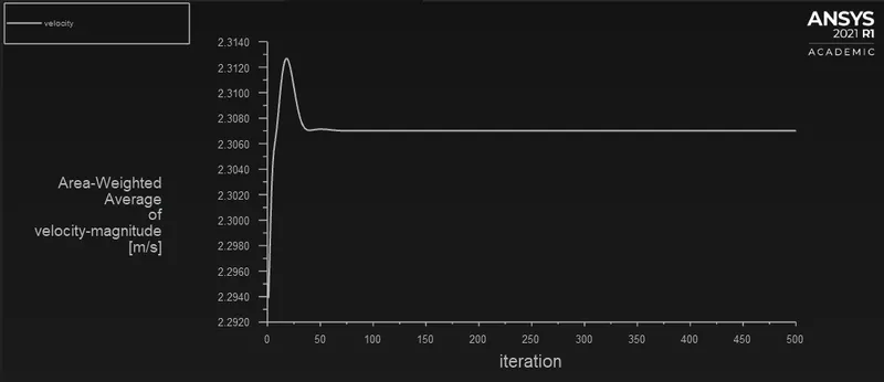
VELOCITY PROFILE:
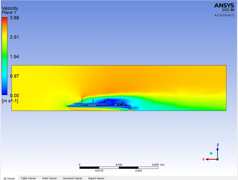
VELOCITY CONTOUR:
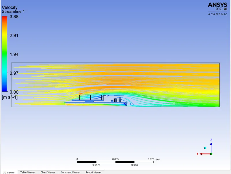
VELOCITY STREAMLINE:
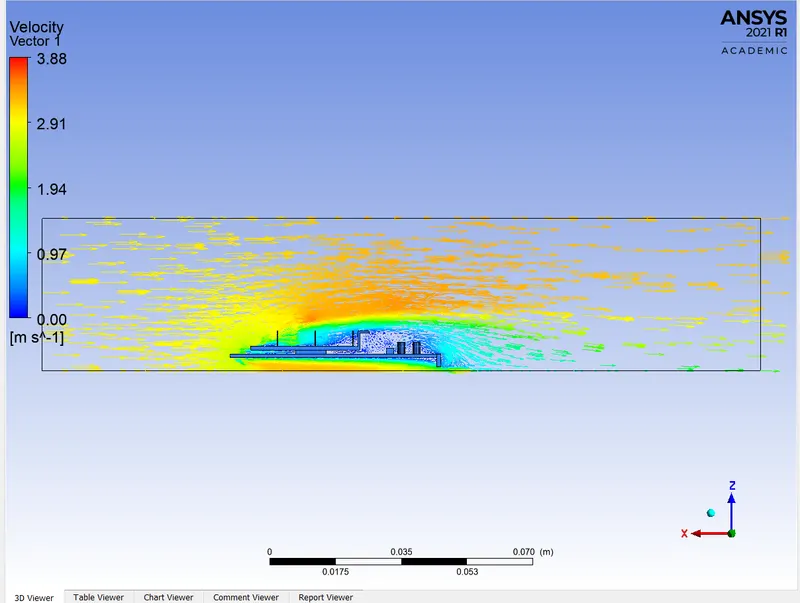
VELOCITY VECTOR:
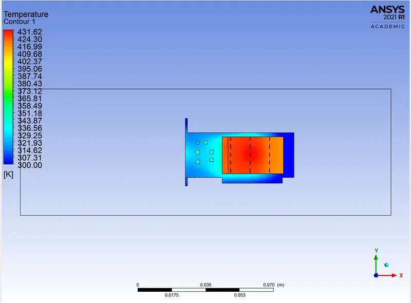
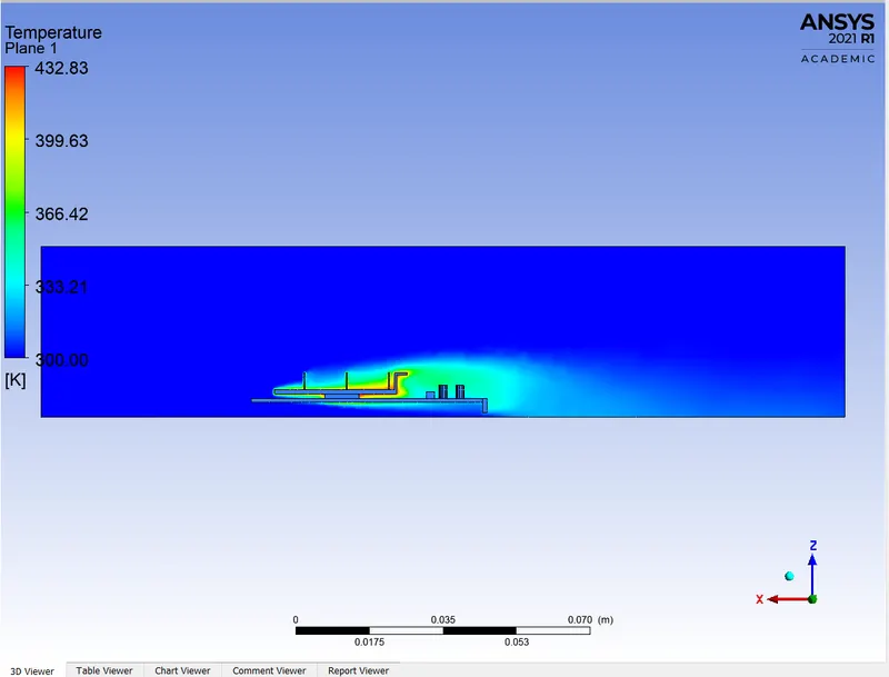
TEMPERATURE CONTOUR:
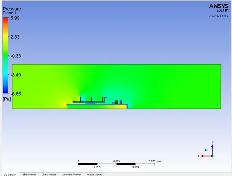
PRESSURE CONTOUR:
WALL ADJACENT TEMPERATURE:
HOTSPOTS:
FOR CASE 3 – VELOCITY = 5M/S
RESIDUAL:
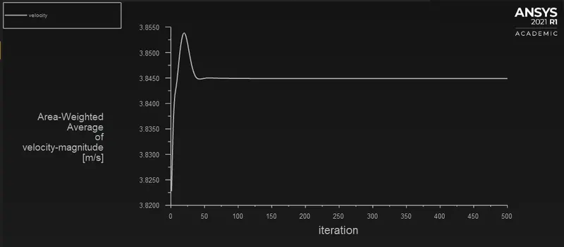
VELOCITY PROFILE:
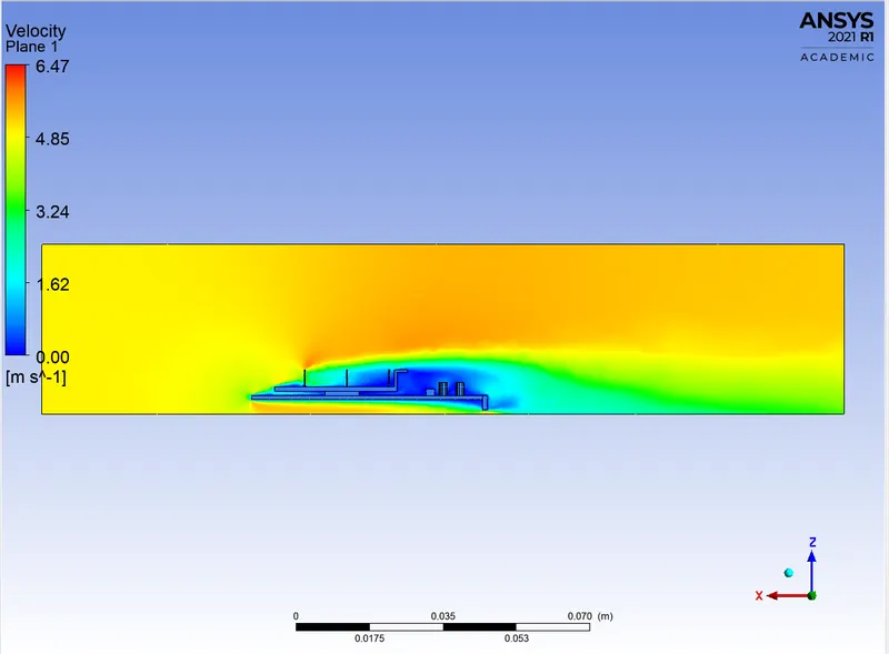
VELOCITY CONTOUR:
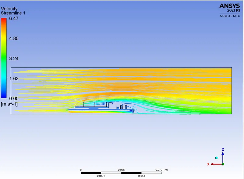
VELOCITY STREAMLINE:
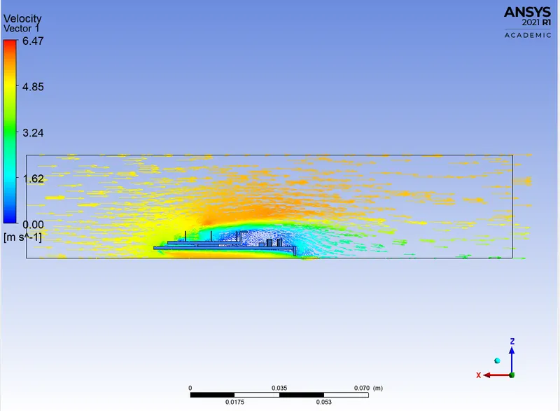
VELOCITY VECTOR:
TEMPERATURE CONTOUR:
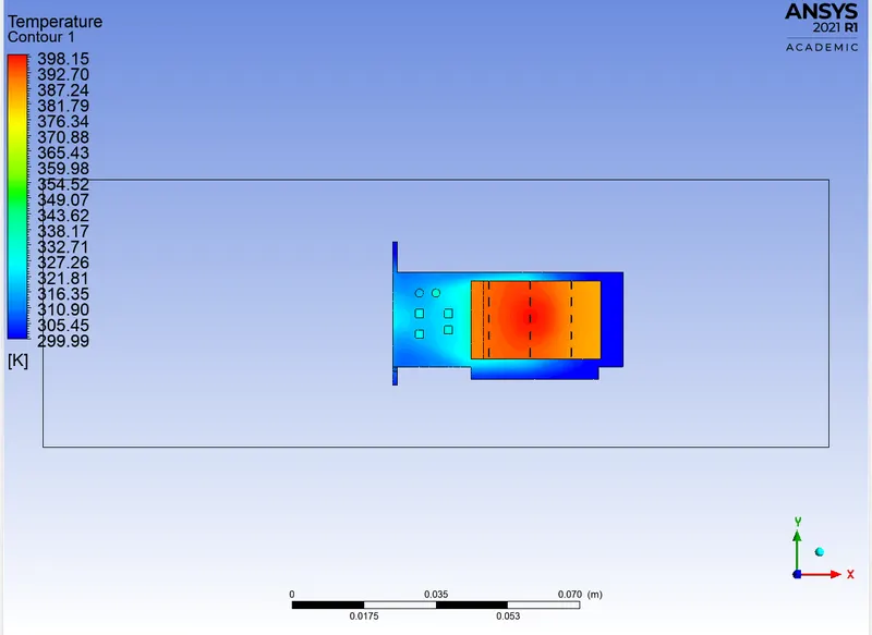
PRESSURE CONTOUR:
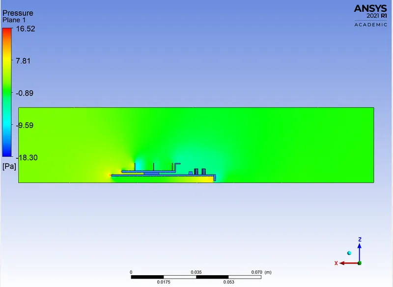
WALL ADJACENT TEMPERATURE:
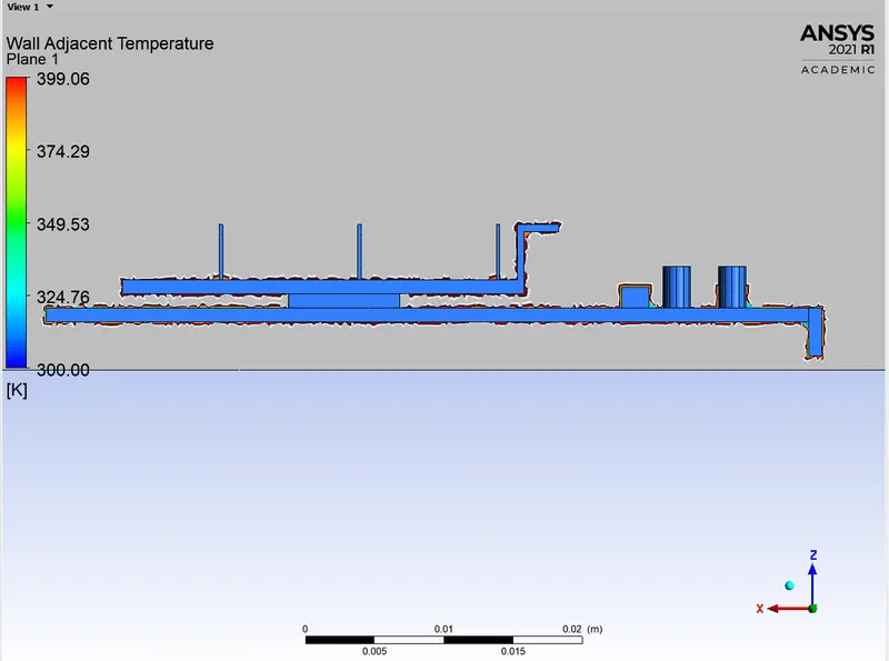
HOTSPOTS:
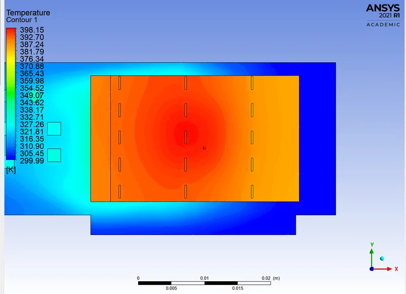
SUMMARY:
|
CASES |
VELOCITY(m/s) |
MAX. TEMPERATURE(K) |
|
Case 1 |
1m/s |
560.38k |
|
Case 2 |
3m/s |
431k |
|
Case 3 |
5m/s |
398k |
CONCLUSION:
- As velocity of incoming air increased the maximum temperature reached was decreased. This is due to the fact as air velocity increases, heat transfer convective coefficient increases so heat transfer to the surrounding increases and temperature attained by the material decreases.
- Due to recirculation of air at rear face of fins temperature is lower than front face of fin.
- For fast and better cooling the components air velocity must be greater
- With increase in velocity maximum conjugate heat transfer coefficient at processor wall increases.