Week 6 - CHT Analysis on a Graphics card
CHT Analysis on a Graphics card
Aim: To perform a steady-state conjugate heat transfer analysis on a model of a graphics card.
Objective:
- Run the simulation by varying the velocity from 1m/sec to 5m/sec for at least 3 velocities and discuss the results.
- Find out the maximum temperature and heat transfer coefficient attained by the processor.
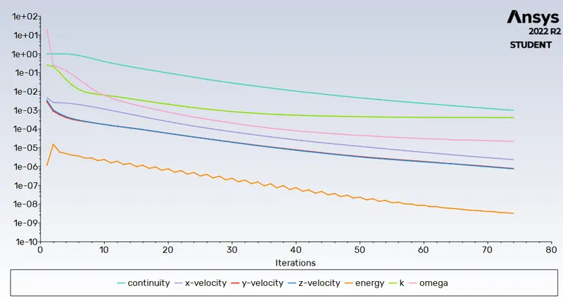
- Prove that the simulation has achieved convergence with appropriate images and plots.
- Identify potential hotspots on the model.
Theory:
CHT:
Conjugate heat transfer is defined as the heat transfer between two domains by exchange of thermal energy at the interfaces of faces.
Procedure:
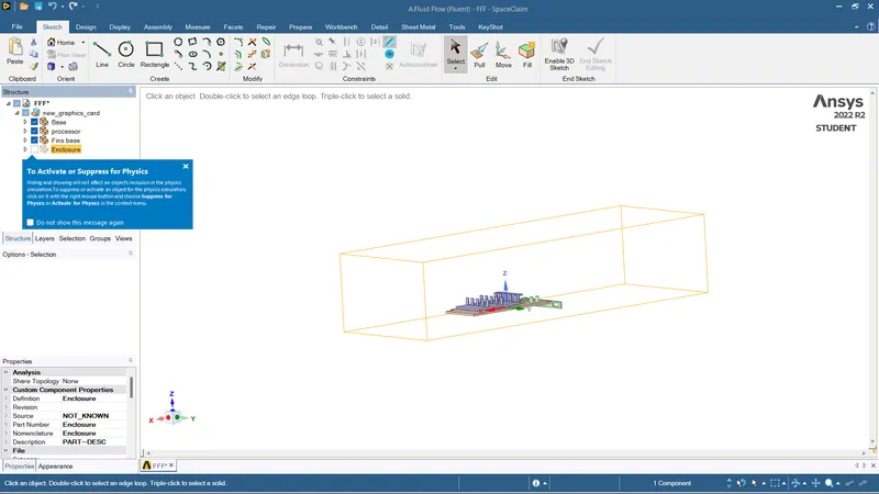
Open the Space claim, Import the Grphic card.
Meshing:
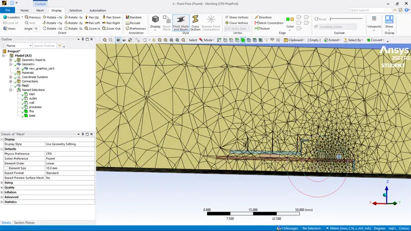
Assign the names accordingly to the parts.
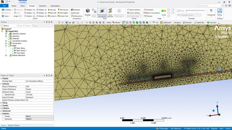
Mesh with 10mm element size.
Setup:
Solver
Steady state
K-omega model
Assign the material with particular property
Solid materials:
Base - FR-4
Fin - Aluminium
Processor - Silicon
Fluid materials:
Enclosure - Air
Inlet velocity =1 m/s
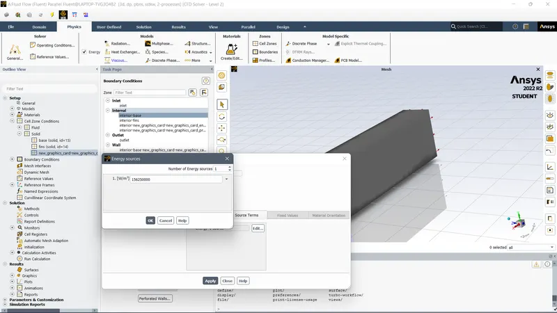
Graphics Card Power = 10W
Volume of the card = 8 x 8 x 1 = 64 mm^3
Heat Generated = P /V= 1.5625e8 Wm^3
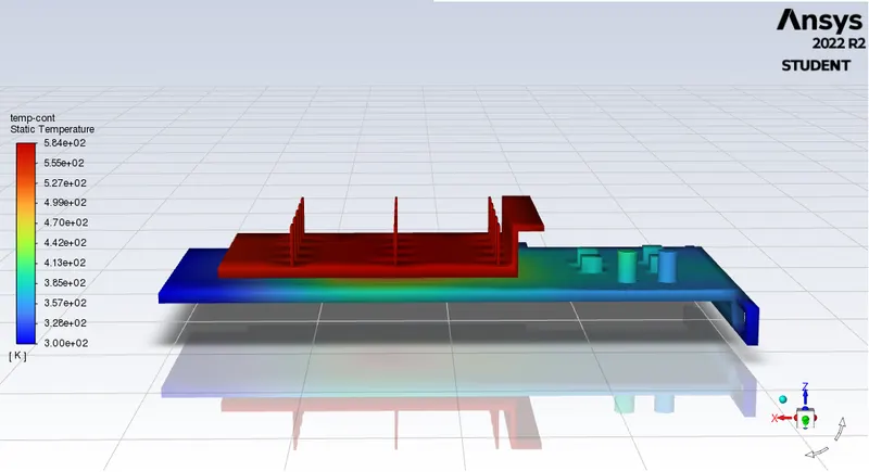
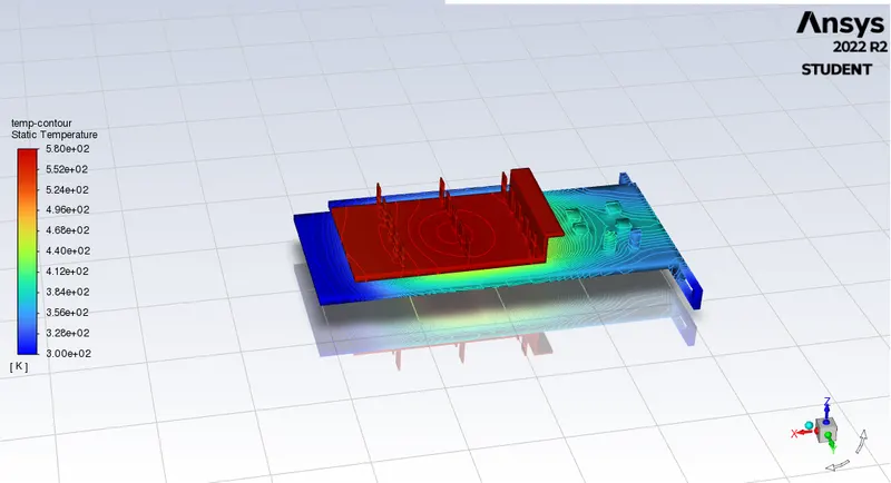
Temperature contour around materials:
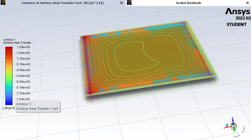
Heat transfer co-effecient:
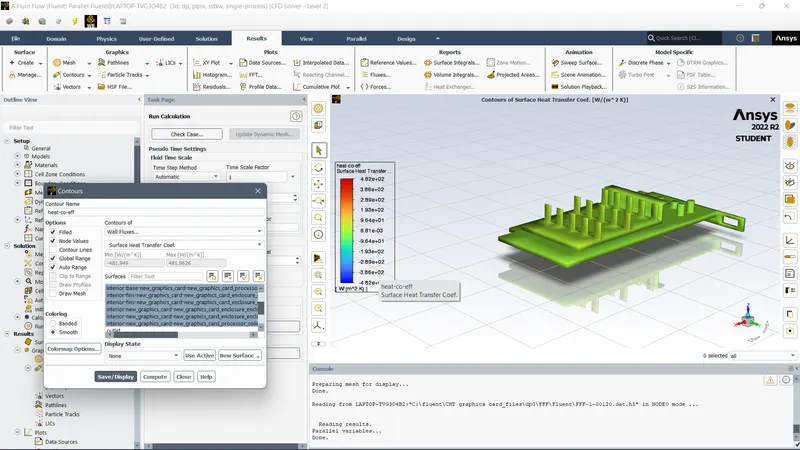
Heat transfer co-effecient of processor:
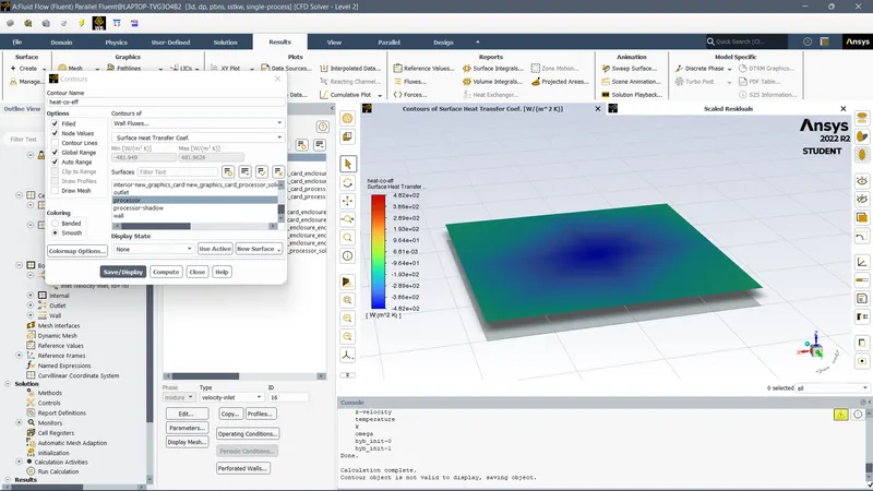
Refined Mesh:
Meshing the individual parts with sizes
Fins size: 0.5 mm
Processor: 0.2 mm
Base: 2 mm
velocity = 1m/s
Temperature of proceesor:
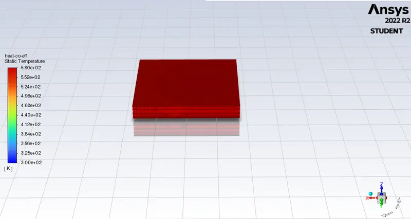
Heat co-effecient of processor:
Temperature contour:
(Solution converge)Residuals:
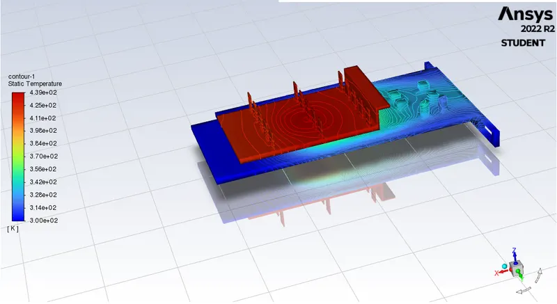
For velocity =3 m/s.
Temperature contours:
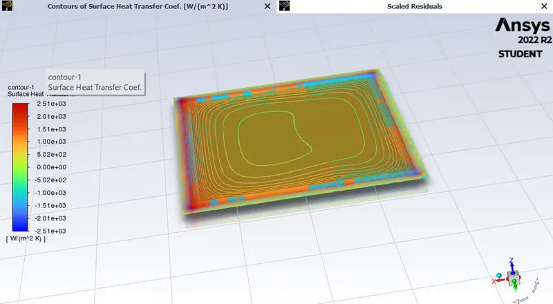
Heat transfer co-effecient of processor:
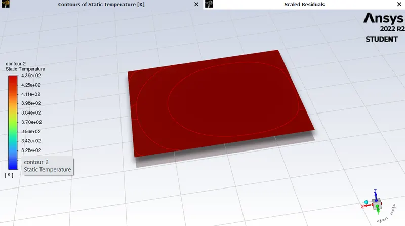
Temperature of processor:
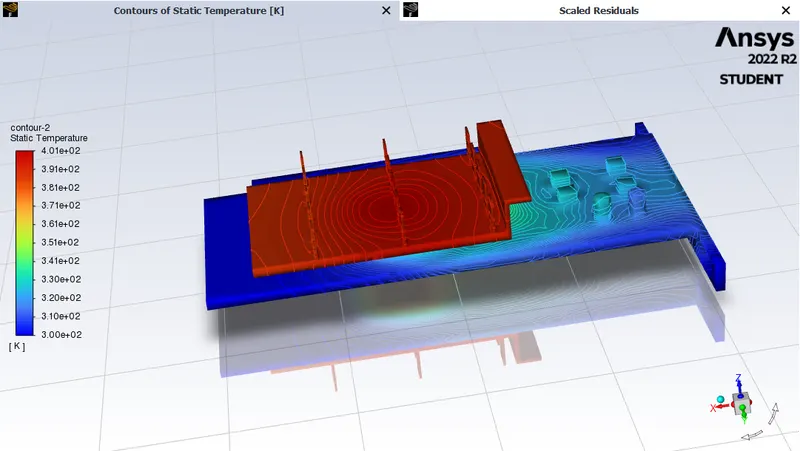
For velocity = 5m/s
Temperature contours:
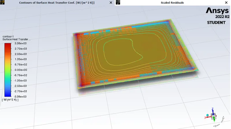
Heat transfer co-effecient of processor:
Temperature of processor:

Conclusion:
It better to run fine mesh at required to display the temperature and heat transfer co-effecient properties accurately.
It can be observed that the temperature of components decreases as the inlet velocity increases from 1 m/s to 5m/s, also proving that higher velocity results in better cooling.