Week 6 - CHT Analysis on a Graphics card
AIM:
Perform a steady-state conjugate heat transfer analysis on a model of a graphics card.
INTRODUCTION:
Conjugate heat transfer is a behavioural analysis where convective (transfer between fluid) and conductive (transfer between solids) heat transfer takes place in a system. This combination of heat transfer has forced or natural convection where fluid is dominated by convection and solid is dominated by conduction. Cooling of gas turbine blade, heat exchangers and cooling of graphic card all are examples of conjugate heat transfer problem. Heat transfer from solid to fluid and fluid to solid takes place.
OBJECTIVE:
- Run the simulation by varying the velocity from 1m/sec to 5m/sec for at least 3 velocities and discuss the results.
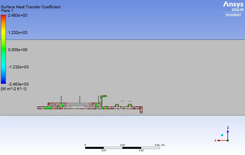
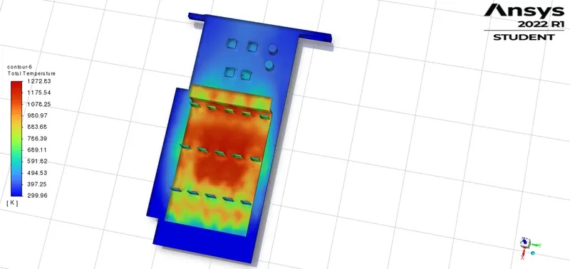
- Find out the maximum temperature and heat transfer coefficient attained by the processor.
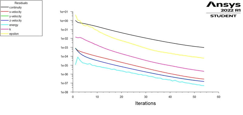
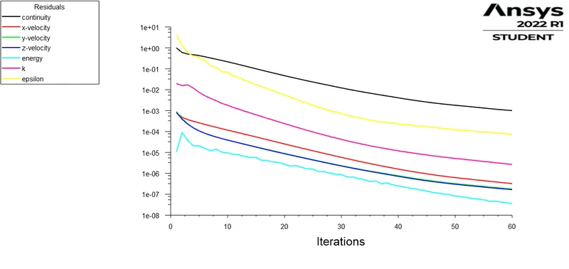
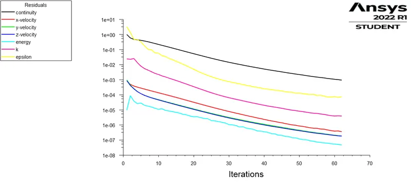
- Prove that the simulation has achieved convergence with appropriate images and plots.
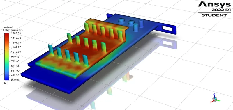
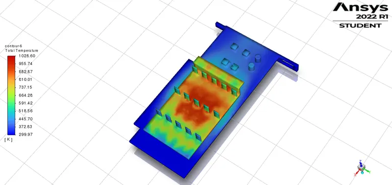
- Identify potential hotspots on the model.
NUMERICAL METHODOLOGY:
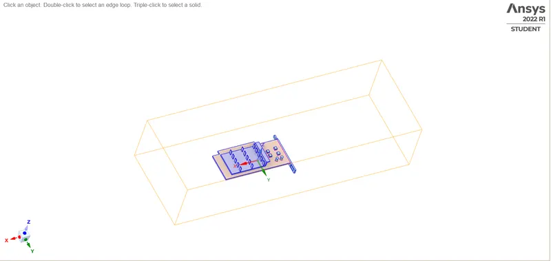
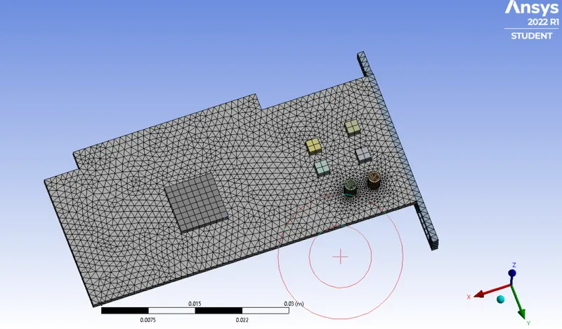
The graphic card is the main component which is responsible for the better quality of the visuals displayed. In this experiment we study the heat generated by the graphic card with effect of different inlet velocities. There are four parts enclosure, fin base, base and processor. The model used can be seen in the image:
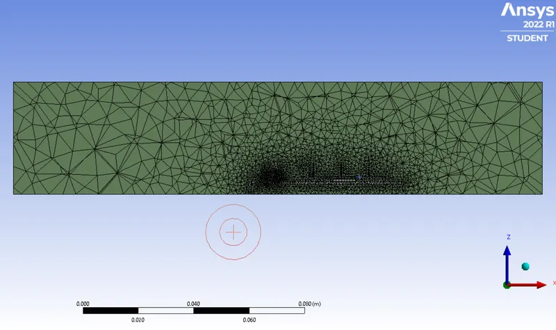
First a base mesh with a default size of 0.010289m is generated and then following modification is done by looking the result at different regions. Those results are not shown here.
Mesh Description:
Base mesh for all regions : 4mm
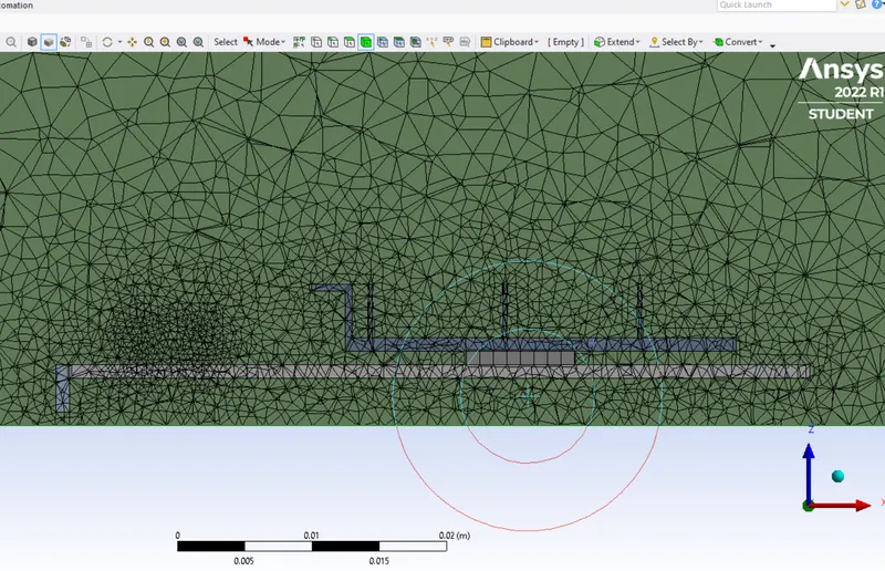
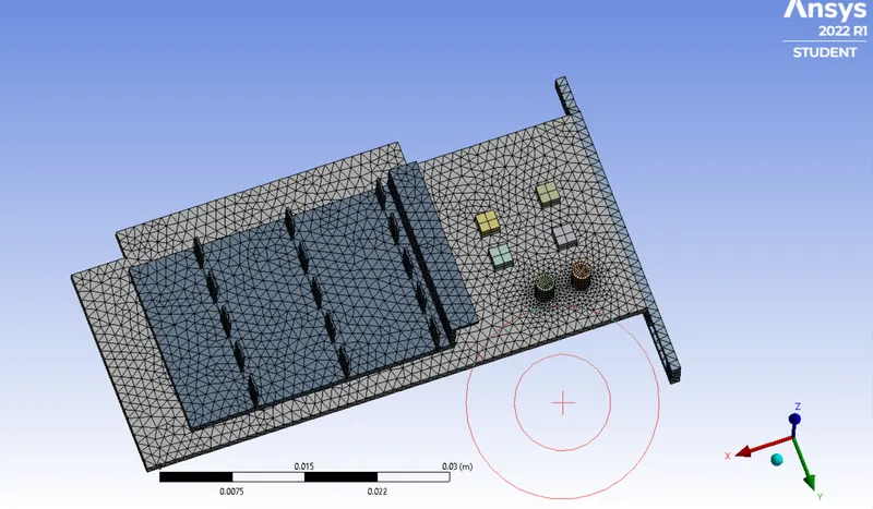
Body sizing (Fin base and graphic card base) : 0.09mm
Body sizing (Processor) : 0.2 mm
Edge sizing for cylindrical part.
Number of elements : 401482
The final mesh will look like
Solver setup
- Solver is steady state pressure based and velocity is changed from 2 to 5 m/s for three different cases.
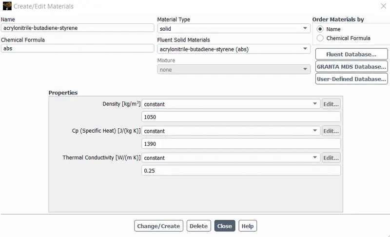
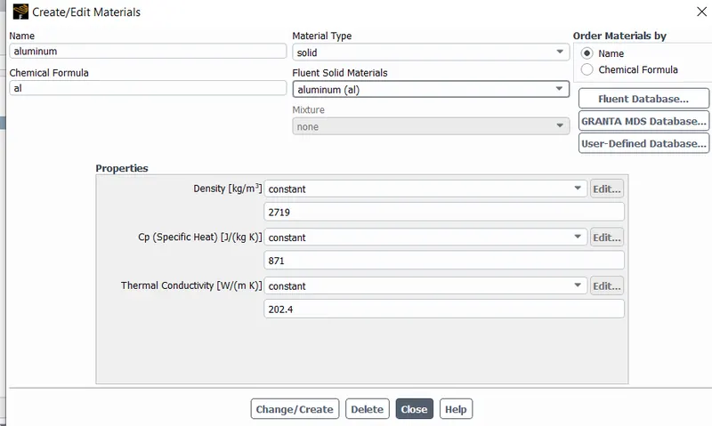
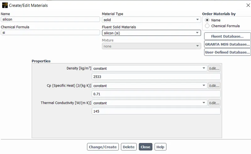
- Materials : Solid - Fin base (Aluminium), Solid - Processor (Silicon), Solid - Graphic card base (abs) and Fluid - enclosure(air).
- Energy equations are solved as it is a conjugate heat transfer problems.
- k-`epsilon` is chosen as a turbulence model.
- Heat is generated in the processor. `q_(Gen)=1093750000 w/m^3`, if graphic card power is 70 watt.
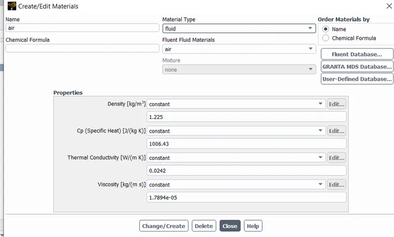
Boundary condition
- Air at the inlet is given fixed value of velocity and temperature.
- At the outlet zero gauge pressure mentioned.
- At all the walls of solid-solid and solid-fluid coupled boundary condition is specified.
RESULT:
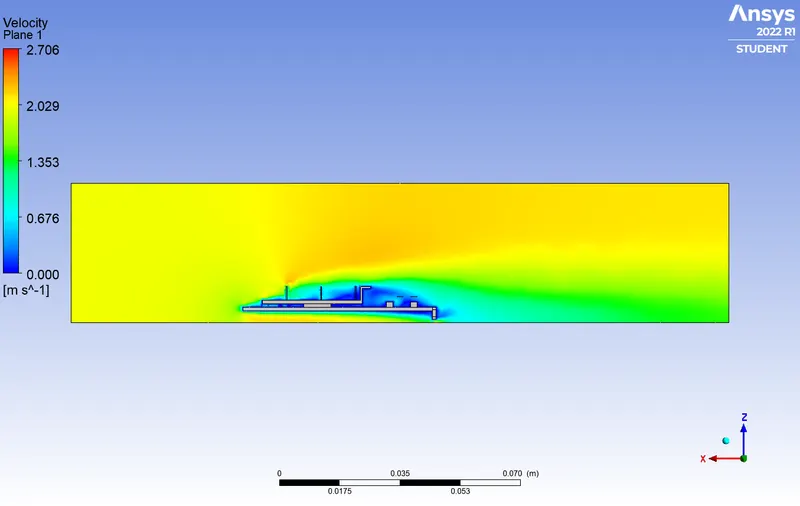
Three different velocity are cosidered 2, 3 and 5m/s to see the effect of velocity on temperature change.
Case-1
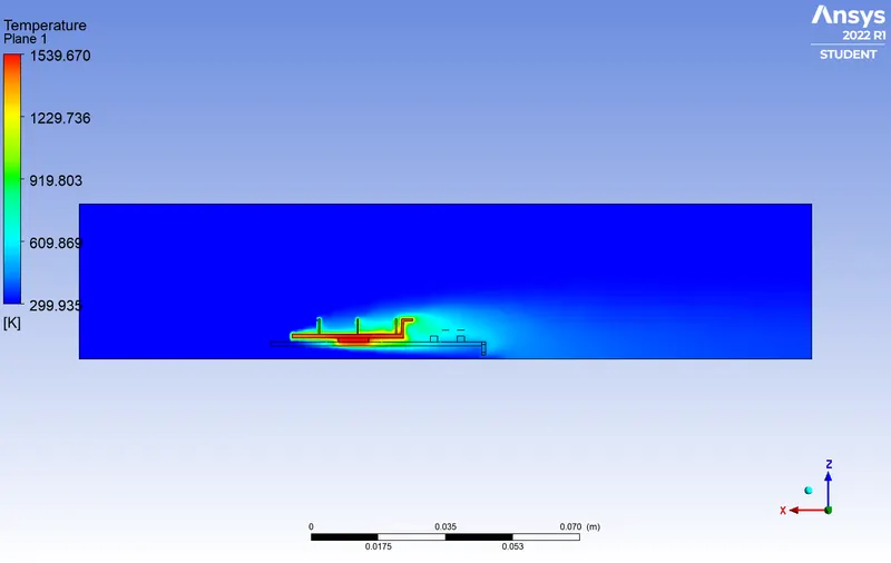
Inlet velocity=2 m/s and temperature 300 k.
Case-2
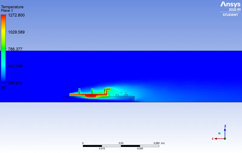
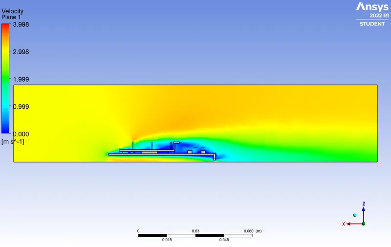
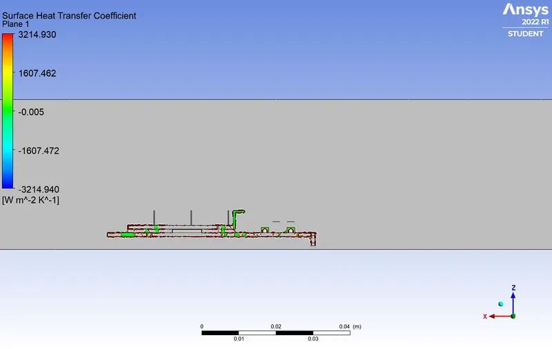
Inlet velocity = 3 m/s and temperature 300 k
Case-3
Inlet velocity = 5 m/s and temperature 300 k.
CONCLUSION:
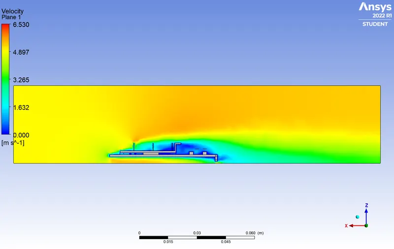
- As the incoming fluid velocity is incresed maximum temperature reduced.
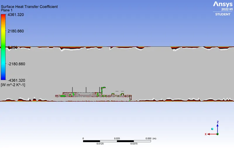
- The surface heat transfer coefficient increased with velocity.
- At some location wall heat transfer coefficient is negative may be heat is transfered from fluid to solid at that location.
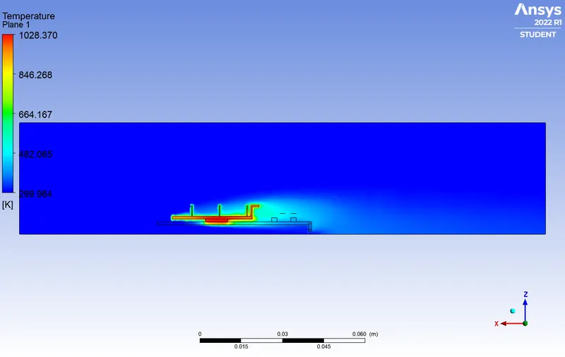
- Higher temperature is noticed near the Processor of fin and graphic card base.
- The maximum temperature can be observed from the above contour plots.