Week 6 - CHT Analysis on a Graphics card
CHT Analysis on a Graphics card
Objectives:
- Run the simulation by varying the velocity from 1m/sec to 5m/sec for at least 3 velocities and discuss the results.
- Find out the maximum temperature and heat transfer coefficient attained by the processor.
- Prove that the simulation has achieved convergence with appropriate images and plots.
- Identify potential hotspots on the model.
INTRODUCTION
Conjugate heat transfer(CHT) analysis are performed where there is heat transfer taking place between solid and fluid. The conjugate heat transfer analysis allows the simulation of the heat transfer between solid and fluid domains by exchanging thermal energy at the interface between them.
When two bodies at different temperatures are brought into contact, heat transfer occurs until both bodies assume the same temperature at the point of contact. Therefore, a fluid and a solid surface will have the same temperature at the point of contact. This is known as no-temperature-jump condition. During the heat transfer between solid and fluid both conduction and convection process takes places. Heat transferred from the solid surface to the adjacent fluid layer takes places through conduction and after that heat is tranferred through convection through bulk motion of the fluid.To precisely capture this detailed phenomenon of heat transfer through solid to boundary layer to the moving fluid or vice versa conjugate heat transfer analysis is used.
CHT analysis are used in many engineering applications where ever there is heat transfer between a solid and fluid such as HVAC, electronic component design, cooling system design, heat exchangers, battery thermal management, exhaust manifold etc.
Geometry setup:
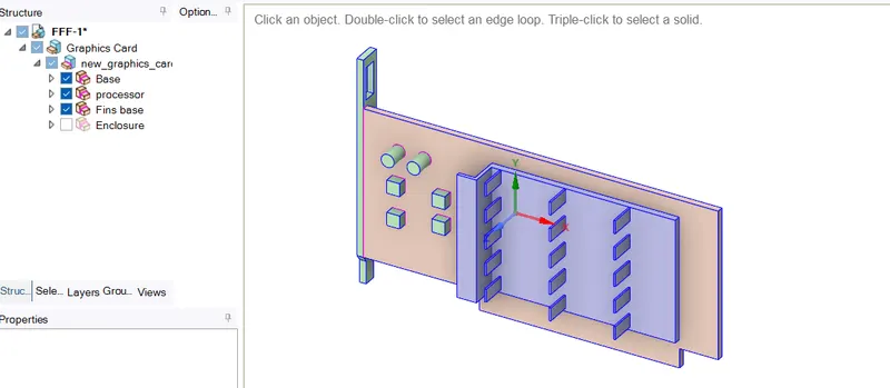
Use Spaceclaim to edit the geometry of the downloaded model of the graphics card which is in the enclosure.
Click on share prep to view any edges in interference so that conformal mesh can be achieved between different components.
Share topology has to be enabled between the different components so that necessary information can be shared between different zones of the mesh.
Mesh setup:
Before generating a base mesh, let's name the different components of the graphic card so it is easier to find them while setting up fluent.
Base, processor and fins are basic name selections which will help us in the simulation. 3. Click generate mesh to create a base mesh, body sizing can be applied for the 3 solid components.
After creating body sizing for the 3 components, generate mesh as that it is considered as a base mesh having more than 1 lakh elements which help us in finding accurate solutions.
After creating the mesh, exit Mesh setup to simulate in fluent.
Mesh settings:
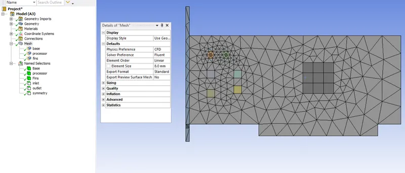
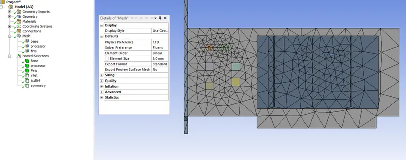
Base mesh setup results @velocity 1m/s
Global mesh setting of element size = 14 mm
1) PCB body sizing element size = 5mm
2) Processor body sizing element size = 5 mm
3) fins body sizing element size = 5mm.
Total elenments : 82145
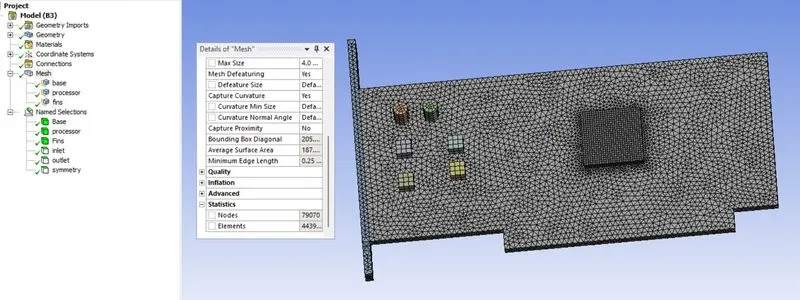
Global mesh setting of element size = 5 mm
1) PCB body sizing element size = 1 mm
2) Processor body sizing element size = 0.4 mm
3) fins body sizing element size = 1 mm.
Total elenments : 4439200
Fluent setup:
Setting up the physics for CHT analysis on a graphics card in ANSYS fluent
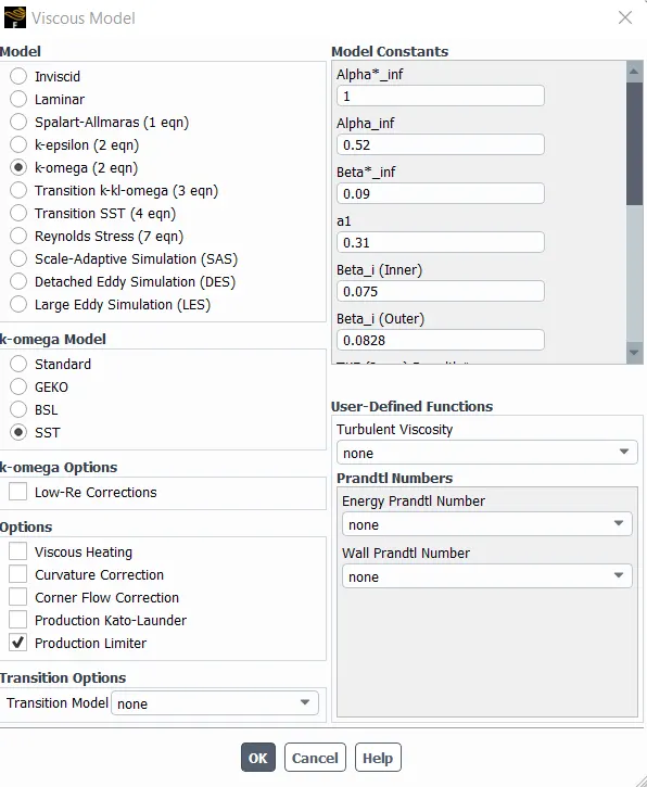
. For this case we are using pressure-based steady state solver
. Velocity formulation - Absolute
Model setup
. Energy
- Viscous-k-omega
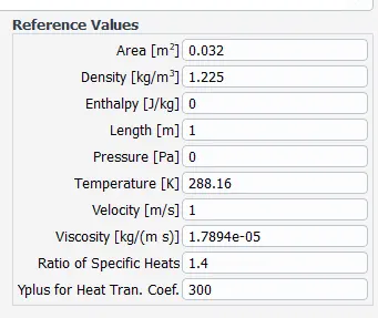
To get the surface heat transfer co-efficient of processor
4 sides wall of processor 8m length and 1m width
A= 0.032m2
Materials & their properties
( created materials)
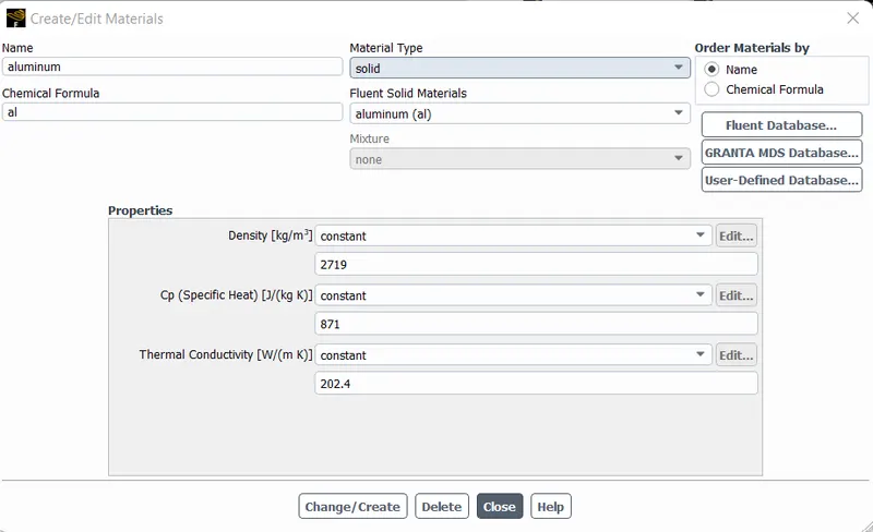
1) Fins --> Aluminium
Standard aluminium is available in Fluent database.
Density = 2719 Kg/m^3
Heat capacity = 871 J/kgk
Thermal conductivity = 202.4 W/mk
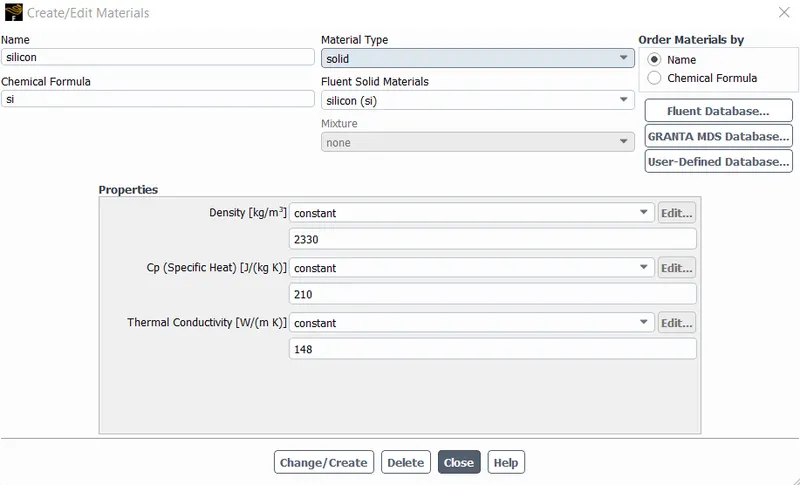
2) Processer --> Silicon
Since the silicon is not available in Fluent's solid database, I had to define it
Density = 2330 kg/m^3
Sprcfic heat = 210 J/kgk
Thermal conductivity = 148 W/mK
3) PCB --> FR4 (glass-reinforced epoxy laminate material) Since the FR4 is not available in Fluent's solid database. I had to define it
Density = 1850 Kg/m^3
Specific heat =1300 J/kgk
Thermal conductivity = 0.26 w/mk
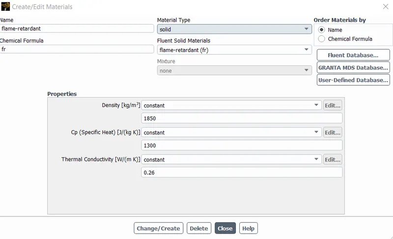
For fulid material air is as the default
Calculation for the Energy source
Let the processor consume 10W of power to work.
Dimension of the processor = 8*8*1 mm^3
So, Energy produced by the processor is156250000w/m3
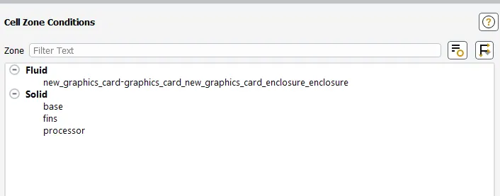
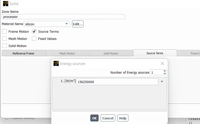
press the initialaze
set max temp and surface heat transfer polts
set requried countures and animations
set the 500 iterations and run the simulation
Solutions and plots
Base mesh setup results @velocity 1m/s
Global mesh setting of element size = 14 mm
1) PCB body sizing element size = 5mm
2) Processor body sizing element size = 5 mm
3) fins body sizing element size = 5mm.
Total elenments : 82145
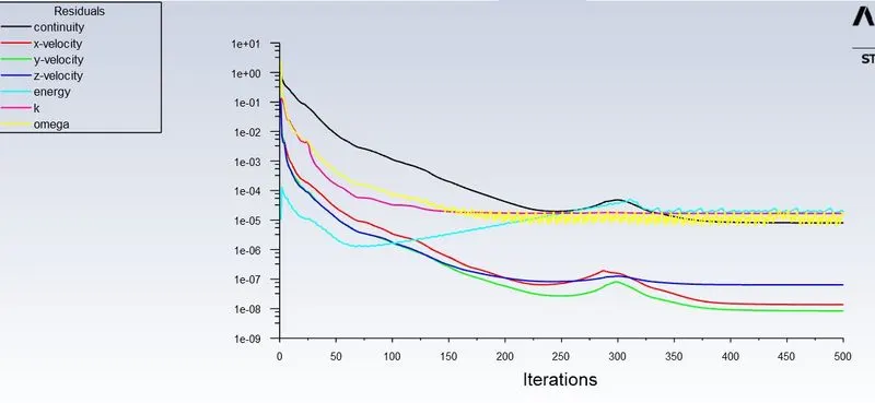
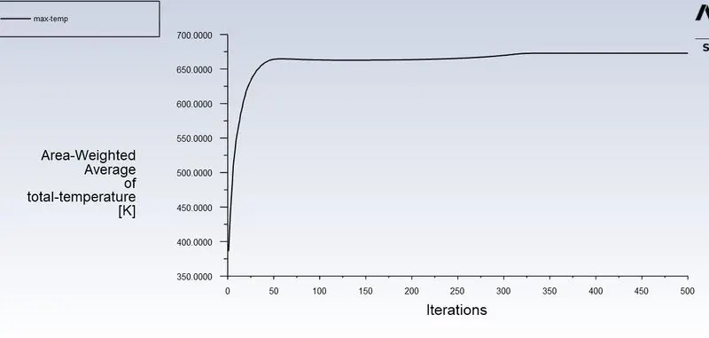
The simulation has achieved convergence
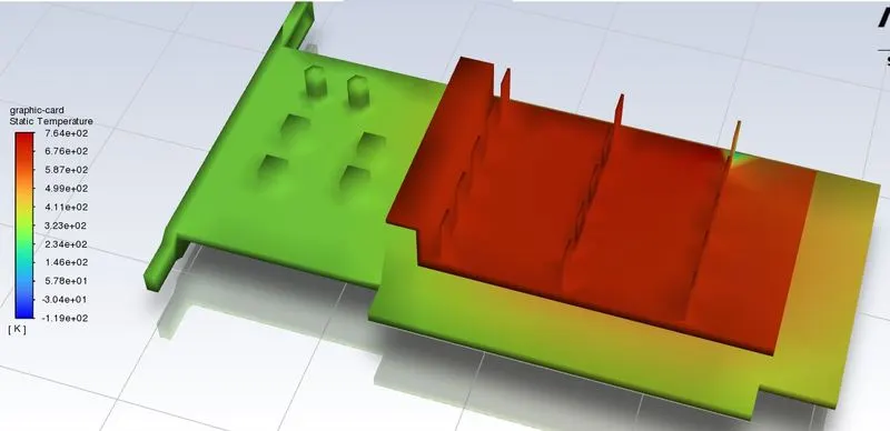
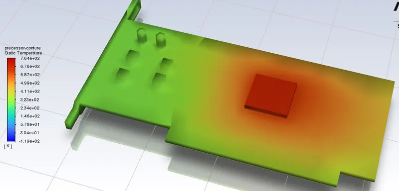
The max temprature of processor is 650k
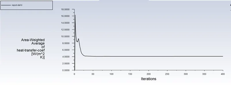
Heat transfer coefficient attained by the processor is 5w/m2k
Refined mesh setup @velocity 1m/s results
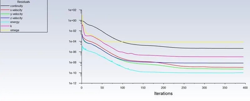
The simulation has achieved convergence
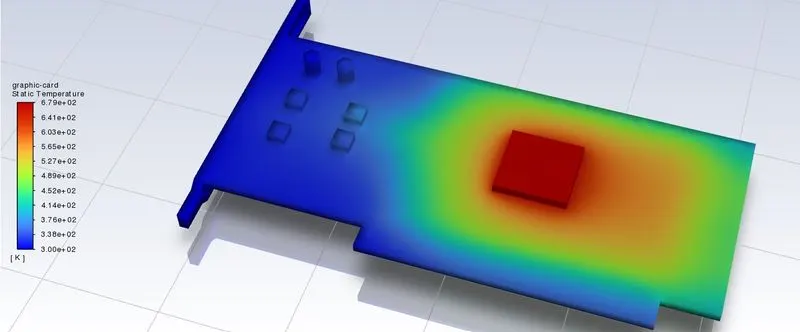
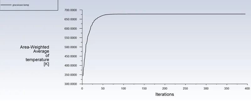
Maximum temperature and attained by the processor is 660k
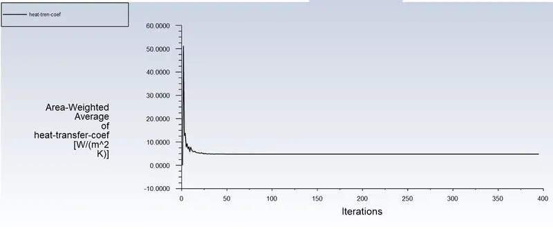
Heat transfer coefficient attained by the processor is 7w/m2k
Refined mesh setup @velocity 3m/s results
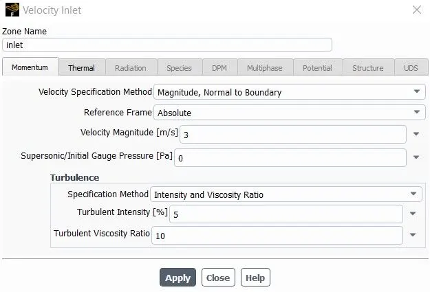
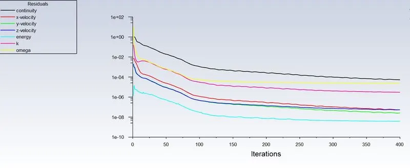
The simulation has achieved convergence
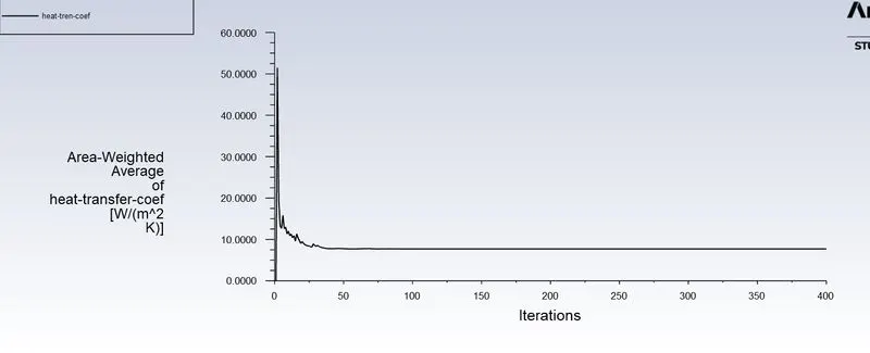
Heat transfer coefficient attained by the processor is 10w/m2k
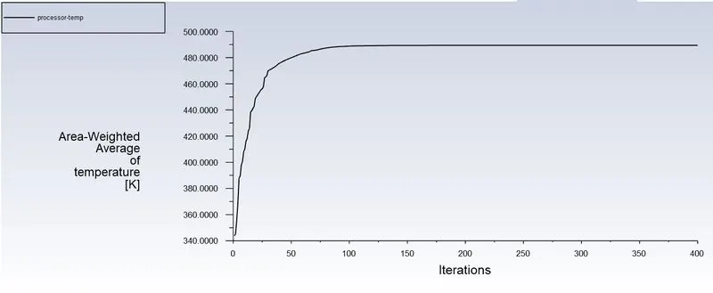
Maximum temperature and attained by the processor is 490k
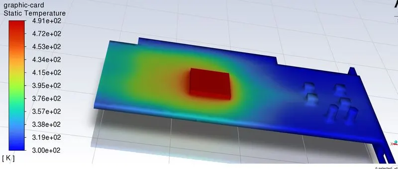
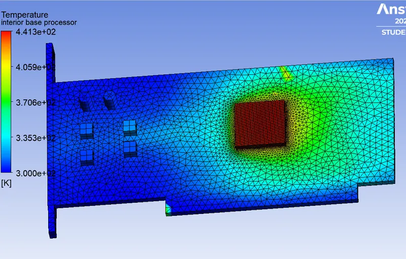
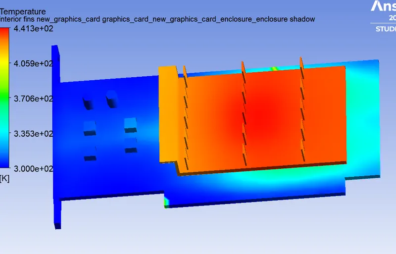
Refined mesh setup @velocity 5m/s results
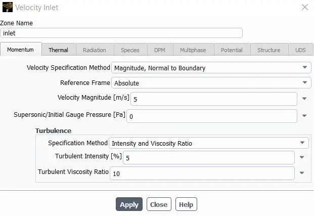
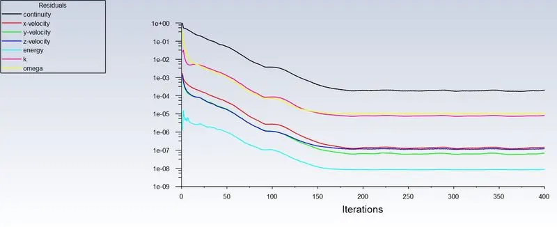
The simulation has achieved convergence
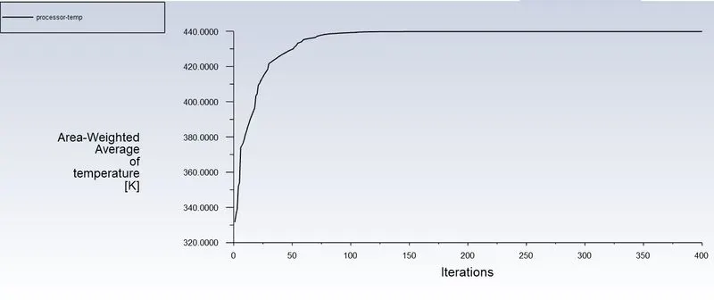
Maximum temperature and attained by the processor is 440k
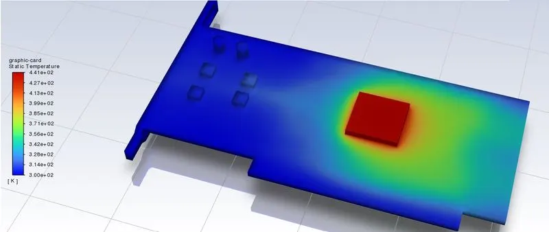
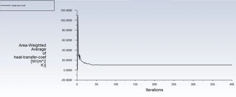
Heat transfer coefficient attained by the processor is 16w/m2k
CONCLUSION
A converged solution for the given sets of input was observed on the basis of repetitive plots in the Residual plot. The processor acted as a source of heat input and thus one of the hotspots for such study
As the number of elements increases the accurate results of temperature distribution is obtained
From the above table, it is fairly notable that, the net temperature of components of graphics cards decreases
with an increase in inlet velocity.
Hence it can be inferred that a higher inlet velocity results in better cooling and lower the average temperature
thus keeping the components safe from damage.
Furthermore, it can be observed that the temperature of components increases as the inlet velocity decreases from 5 m/s to Im/s, also proving that higher velocity results in better cooling.
***************************************************************************************************