Week 6 - CHT Analysis on a Graphics card
AIM
- Simulate by varying the velocity from 1m/sec to 5m/sec for at least 3 velocities and discuss the results.
- Find out the maximum temperature and heat transfer coefficient attained by the processor.
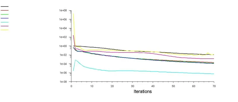
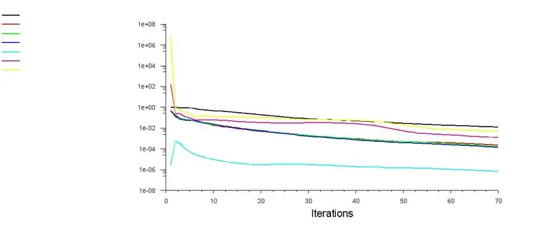
- Prove that the simulation has achieved convergence with appropriate images and plots.
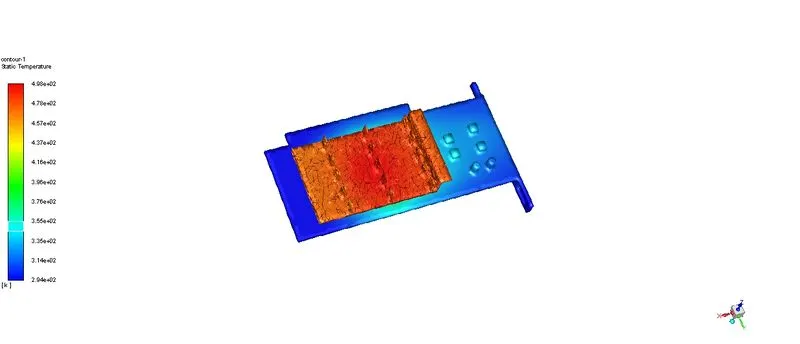
- Identify potential hotspots on the model.
OBJECTIVE
- Loading the model and enabling share topology
- meshing the model properly
- opening the fluent set and setting up the steady-state CHT
- simulating the solution with different inlet velocities
Conjugate Heat Transfer analysis
CHT analysis allows us to simulate the heat transfer between the solid and fluid medium when there is a thermal energy exchange between the interfaces
SOLVING AND MODELLING APPROACH
the problem will be solved for 3 cases
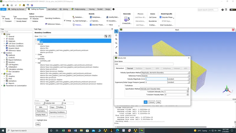
case 1 for a velocity of 1 m/sec
case 2 for a velocity of 3 m/sec
case 3 for a velocity of 5 m/sec
list of steps to be followed
open space claim and loading geometry and activate share topology
open mesh for named selection and meshing (body sizing of processor fins and base)
open fluent set up to setting up the physics and solving the problem
PROCEDURE
1. OPENING SPACE CLAIM AND LOADING THE GEOMETRY
2. Open mesh for named selection and meshing (body sizing of processor fins and base)
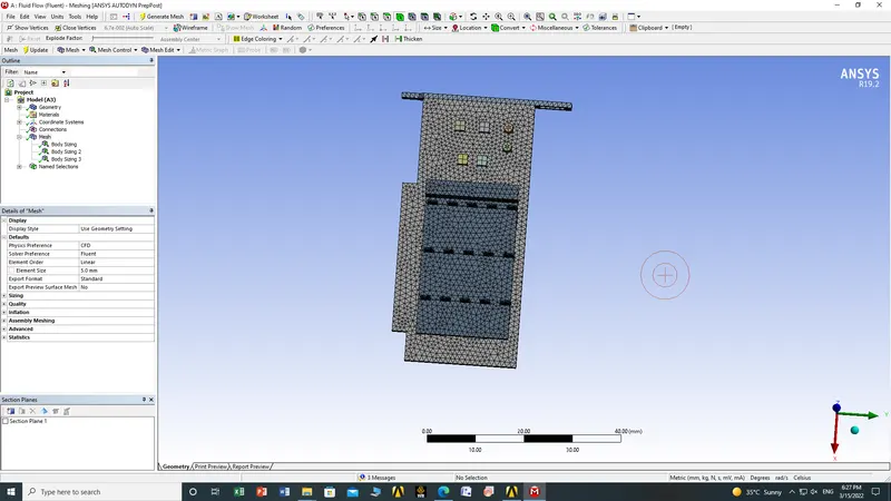
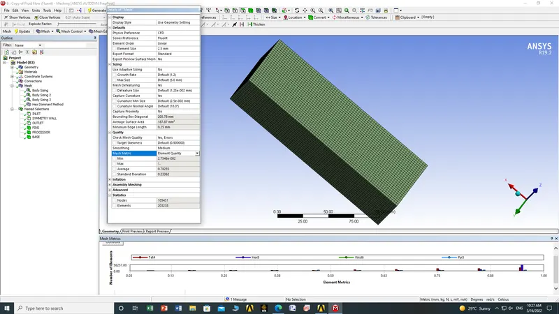
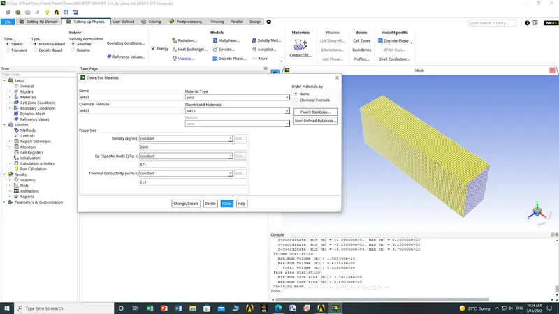
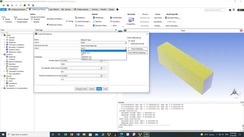
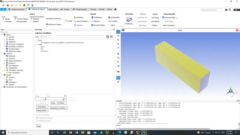
3. open fluent set up to setting up the physics and solving the problem
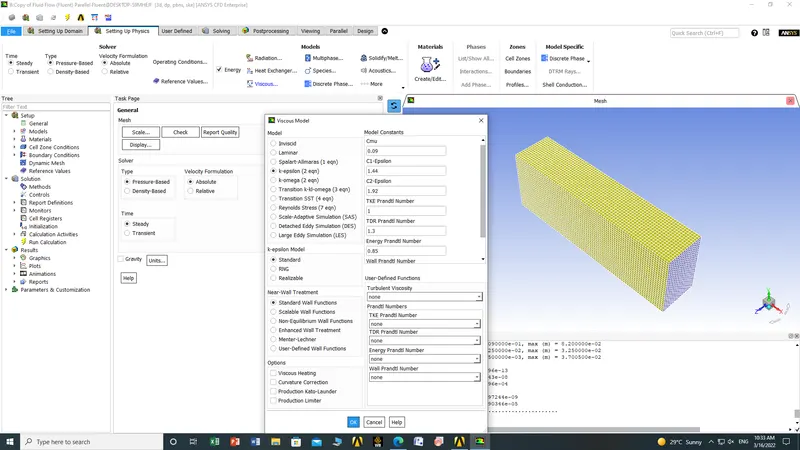
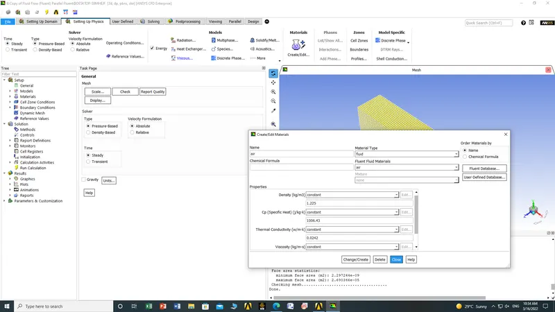

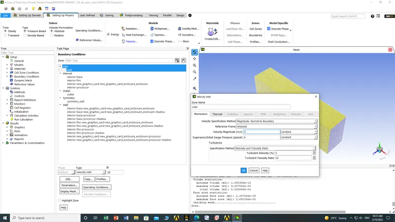
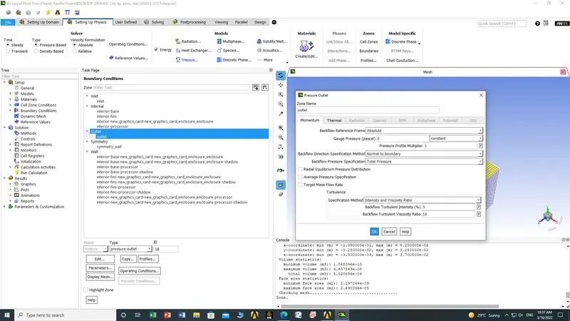
Results for case 1 inlet velocity= 1 m/s
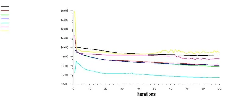
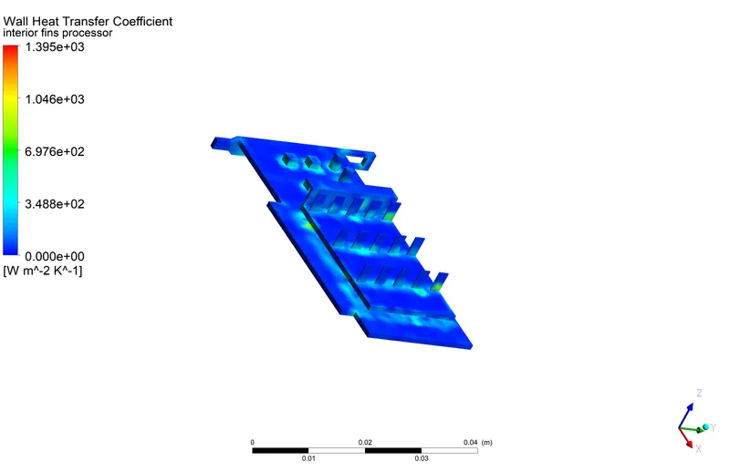
Maximum Value of Wall Heat Transfer Coefficient
1431.4 [W m^-2 K^-1]
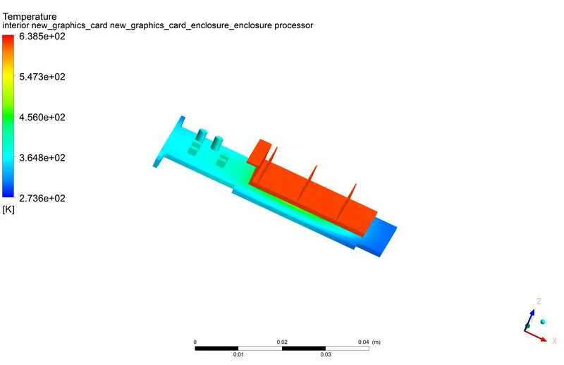
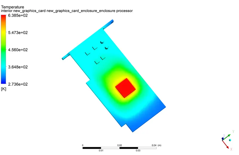
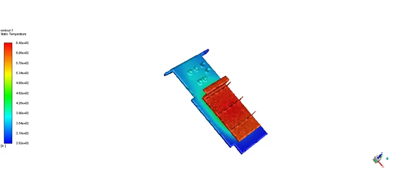
POTENTIAL HOT SPOT
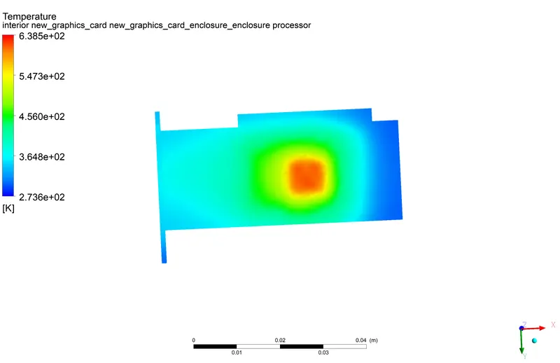
Maximum Value of Temperature on the interior base processor
638.492 [K]
CASE 2 FOR INLET VELOCITY 3 m/s
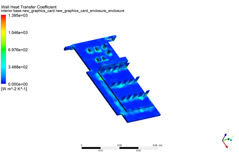
Maximum Value of Wall Heat Transfer Coefficient on interior base
1431.4 [W m^-2 K^-1]
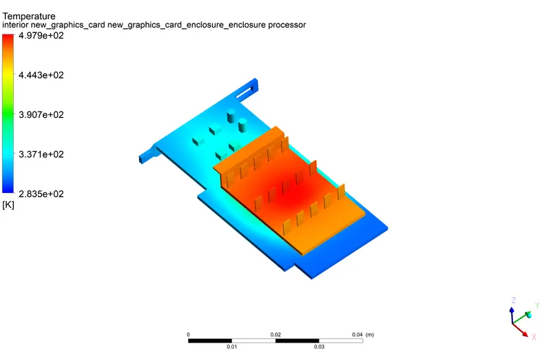
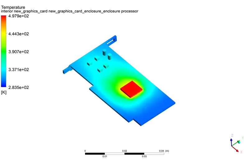
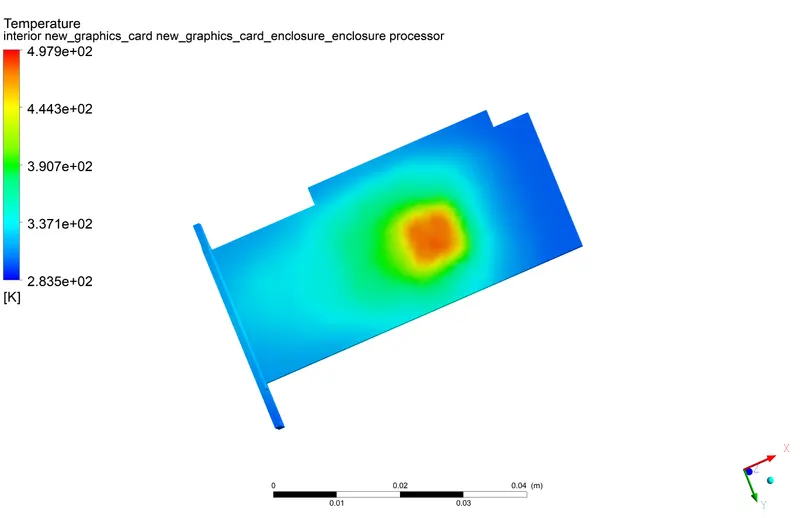
Maximum Value of Temperature on interior base processor shadow
497.935 [K]
CASE 3 FOR VELOCITY 5m/s
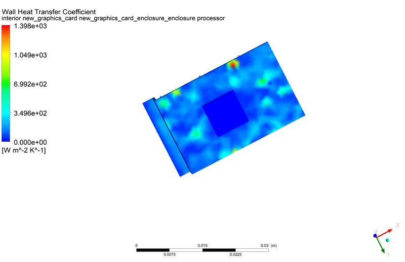
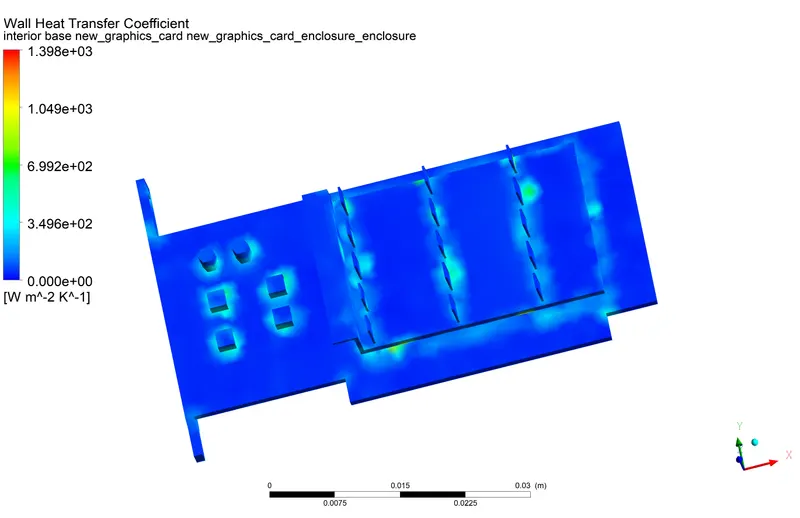
Maximum Value of Wall Heat Transfer Coefficient on interior base new_graphics_card new_graphics_card_enclosure_enclosure
1431.4 [W m^-2 K^-1]
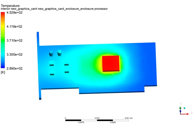
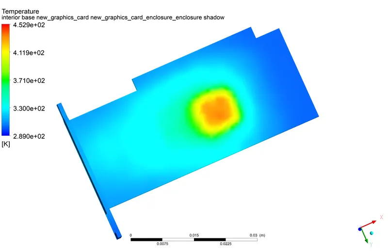
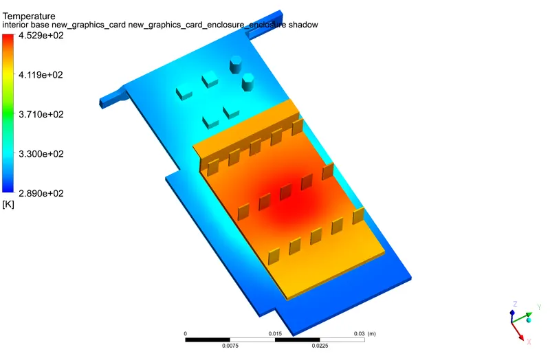
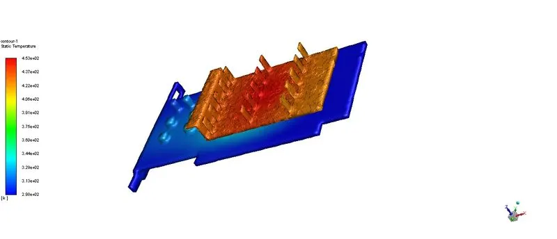
Maximum Value of Temperature on the interior base processor
452.942 [K]
CONCLUSION
from the simulations, it has been observed that as the inlet velocity increases the temperature of the processor reduces
it is because the increased bulk flow of air results in an increased heat transfer coefficient.
hot spots are observed at the top and top of the processor which is in contact with the base and fins. area of hot spot decreases with increased inlet velocity.