CHT Analysis on a Graphics card with wooden base.
CHT Analysis on a Graphics card
Aim:-
- Perform a steady-state conjugated heat transfer analysis on a model of a graphics card.
- Select the appropriate materials for the simulation.
- Mesh the geometry with a desirable combination and Explain the mesh setting used on this model.
- Simulate by varying the velocity from 1m/s to 5m/s for at least 3 velocities and discuss the results.
- Find out the maximum temperature and heat transfer coefficient attained by the processor.
- Prove that the simulation has achieved convergence with appropriate images and plots.
- Identify potential hot spots on the model.
Objectives:-
- Import graphics card model in the space claim and active share topology.
- Mesh the model using proper inflation layer and face sizing.
- Open fluent setup and perform steady-state conjugated heat transfer simulation on meshed model.
- Prove that the simulation has achieved convergence with appropriate images and plots.
- Check the mesh independence of the model by performing the same simulation with different densities of mesh.
- Try simulating solution using different velocities between range 1m/s to 5m/s
- Find out the maximum temperature and heat transfer coefficient attained by the processor.
- Identify potential hot spots on the model.
Conjugate Heat Transfer Analysis
The Conjugate Heat Transfer (CHT) analysis type allows for the simulation of heat transfer between solid and fluid domains by exchanging thermal energy at the interface between them. In solids, conduction often dominates whereas, in fluids, convection usually dominates. The physics of conjugated heat transfer is common in many engineering applications, including heat exchangers, HVAC, and electronic components design.
There is a limit to any system that can hold heat to keep its parts under safe operating conditions. We cannot go past these limits as it will damage the system, Cause failure of the product and system, etc. But what we can do is a measure to cool this system, cool the graphic card so the system keeps running at optimum speed & condition. There are various methods of cooling electrical components, through the fan, thermal pastes, and gels, double fanning, using materials that help dissipate the heat in the fan’s direction, arrangements of components, etc.
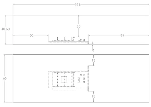
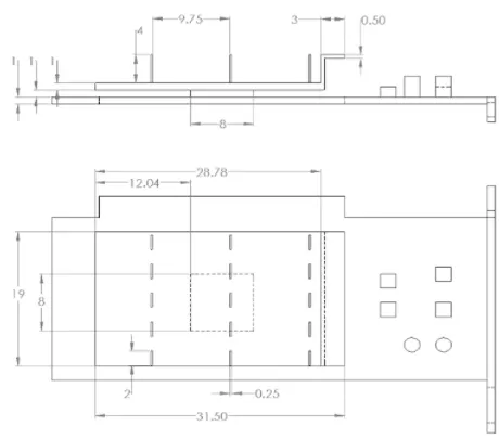
Dimensions of graphics card
Geometry setup:
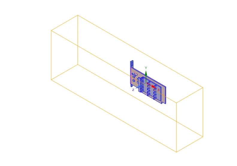
Graphic Card geometry along with Enclosure
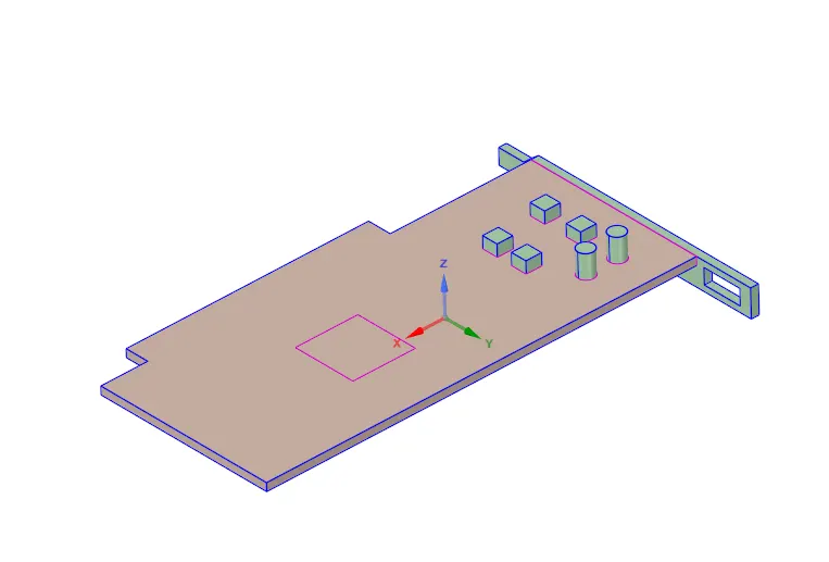
Base
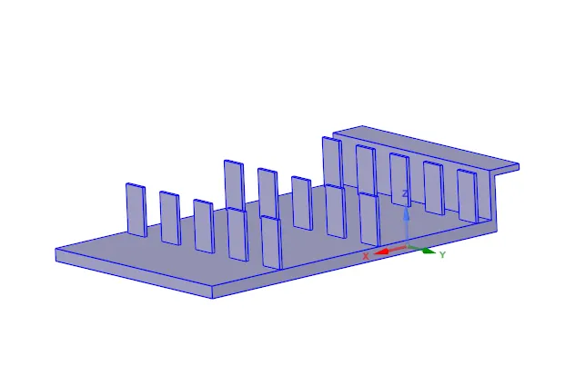
Fins
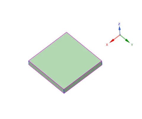
Processors
1. Use Spaceclaim to edit the geometry of the downloaded model of the graphics card which is in the enclosure.
2. Click on share prep to view any edges in interference so that conformal mesh can be achieved between different components.
3. Share topology has to be enabled between the different components so that necessary information can be shared between different zones of the mesh.
Mesh setup:
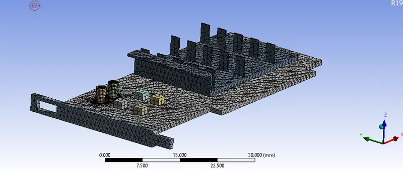
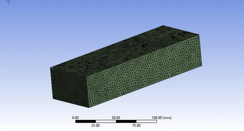
Meshing on graphics card and enclosure
1. Before generating a base mesh, name the different components of the graphic card.
2. Base, processor, and fins are basic name selections that will help us in the simulation.
3. Named selections are created by selecting inlet, outlet and symmetry (4 side walls of enclosure).
4. Click generate mesh to create a base mesh, body sizing can be applied for the solid components.
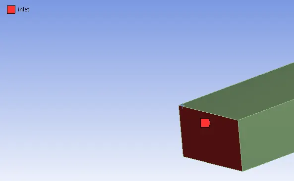
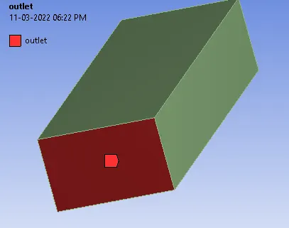
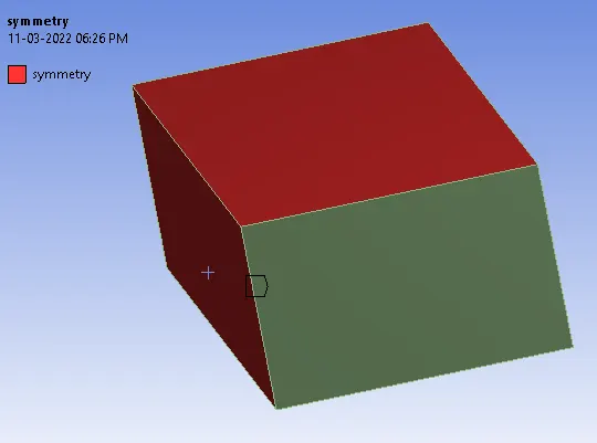 v
v 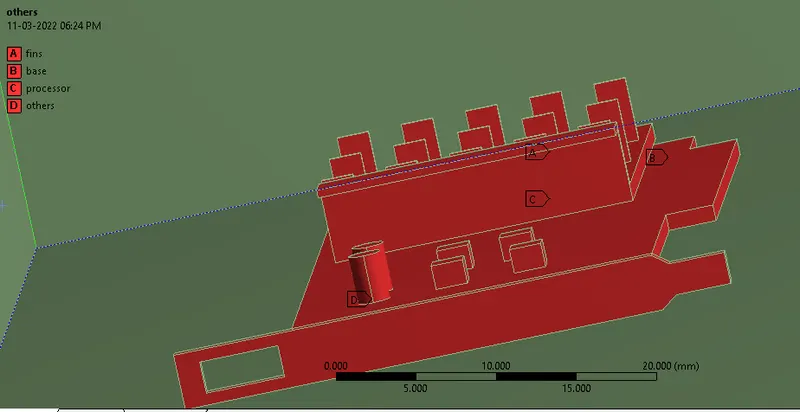
Named Selections
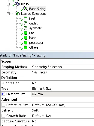
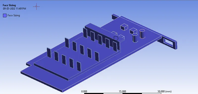
Mesh settings: Global mesh setting of element size = 3 mm.
Face Sizing is taken as 1mm, 0.7mm and 0.5mm.
Solver Setup
In the Fluent settings, the type of solver is used as a pressure base. Velocity formulation was set to absolute and problem simulated as considering steady-state simulation and energy equation enabled as it involves Heat transfer phenomenon.
Turbulence model --> realizable k-e model (Can be used to capture recirculation zones that are not calculated in standard K-epsilon).
Inlet velocity = 2 m/s.3m/s and 5m/s
Sidewalls --> symmetry
Number of iterations = 1000
Heat generation rate:
The Graphics card processor chip is the main heat source, hence, activating the source setting in fluent. Then, here, we have to define how much energy is released from the processor. For this case, 5.97W output is considered(normal working). Now we need it in the form of per volume (volume of the processor).
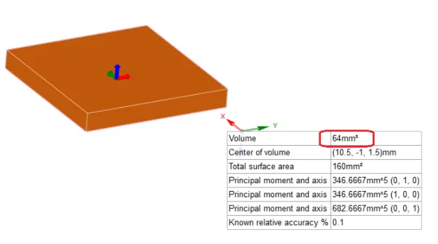
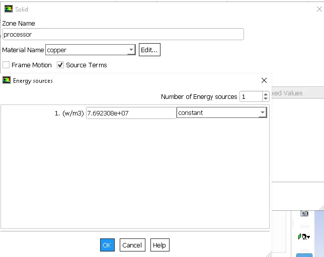
Heat generation rate=`(5.97*10^9)/64=76923080(W/m^3)`.
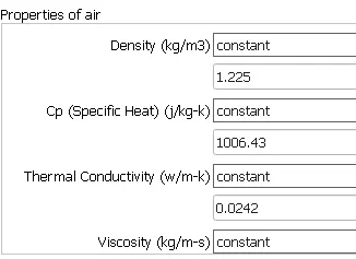
Materials: We need to assign different materials to see the heat transfer coefficients, working of air at different locations, to resonate the working of graphic card assembly and functioning of different modules in electronic devices.
Processor: Copper is assigned to the processor as it needs to sustain heat load for a longer period of time and must be durable to deal with the heat load. Copper is a good conductor of heat thus also will help to diffuse heat towards fins.
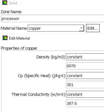
Base: It must be durable and intact. The material must be least conductive among all the components to protect another assembly from heat and save the plastic parts from melting. Wood is chosen for the base which is having poor conductivity.
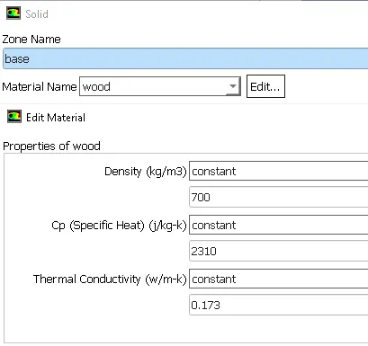
Fins: Important function of fins is to carry and dissipate the maximum amount of heat in the ambiance. Therefore conductivity of the material used in fins must be as high as possible. Therefore copper will be the best material.
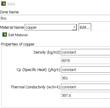
Others: The rest components are taken of aluminum.
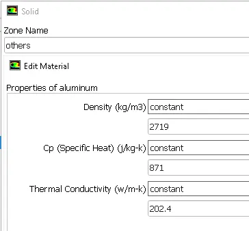
Enclosure: Air
Properties:
A parametric study was created and the input parameters were defined as face mesh size and velocity. The output parameters are considered as average temperature and wall function heat transfer coefficient.
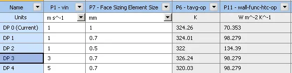
As shown in the above figure; a mesh convergence study has been done by changing the face element size by 1mm, 0.7mm and 0.5mm. the 0.7 showed the reduction in results but after 0.5 mm mesh results started to increase in magnitude. 0.7 mesh was selected for further simulations.
1) Results for velocity of 1m/s are:
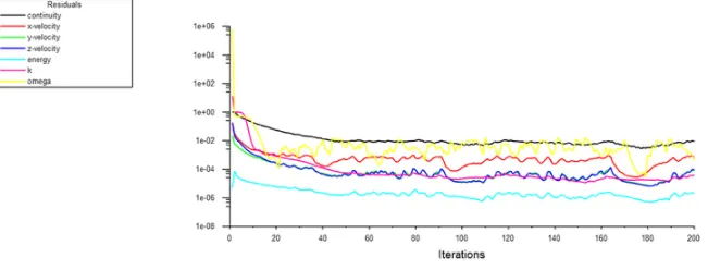
The residual chart exhibits that all the entities giving fluctuating results in the same range as the results getting calculated with the number of iterations. Therefore we can stop at the 200th iteration and considered it as a converged result.
Some post-processing is done using Tecplot 360.
Tmax=355K
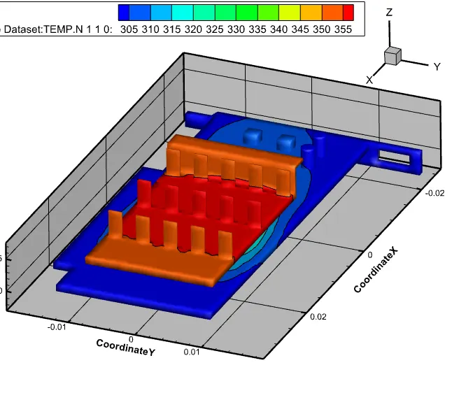
Temperature contour
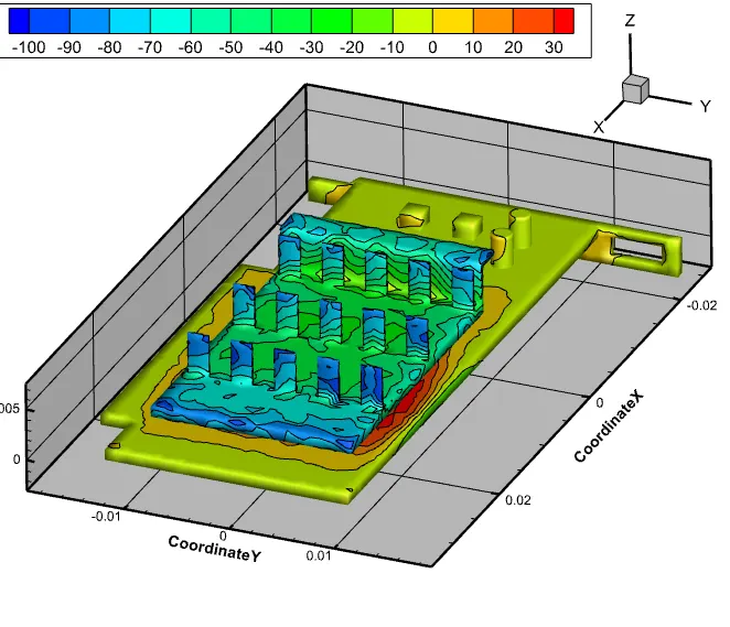
Wall Heat Transfer Coefficient
The heat transfer coefficient is very high at the boundary surface of the first row of fins where the pressure is very low and velocity is increasing.
2) Results for velocity 3m/s
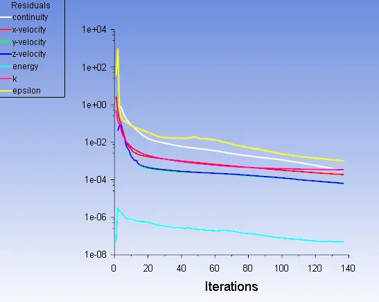
Results converged at the 136th iteration.
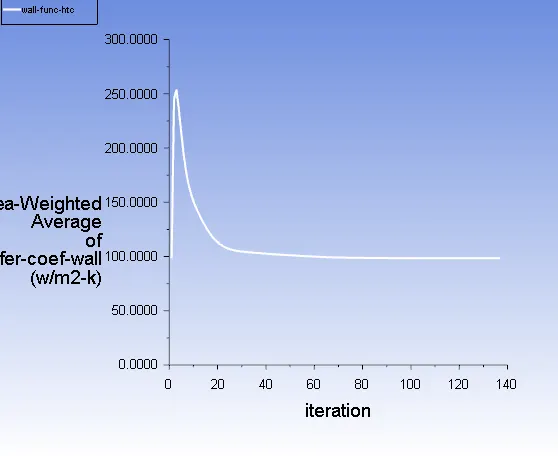
Area Weighted average of wall HTC is shown, which converged at `(100W/(m^2.K))`.
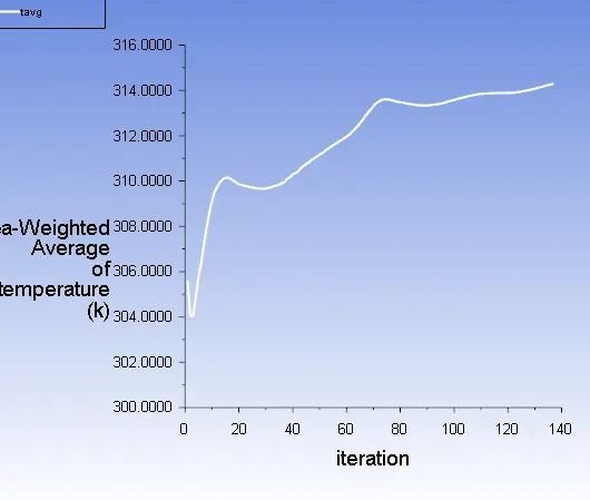
The average temperature is recorded as 314K.
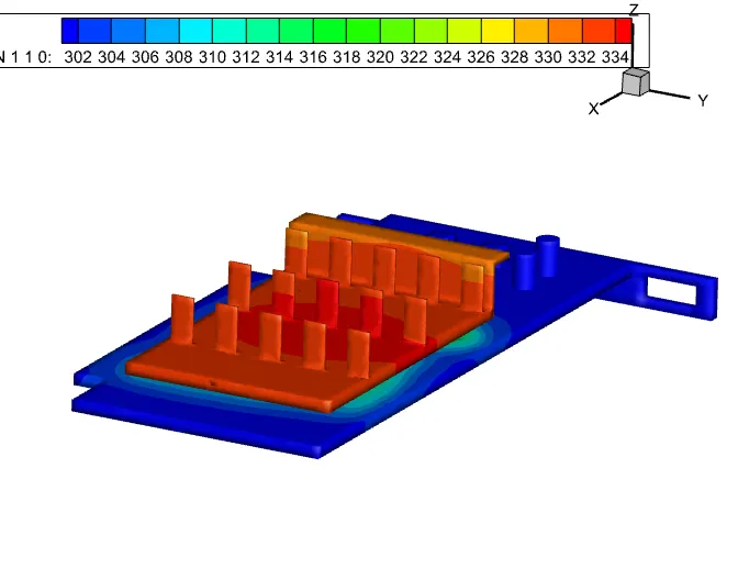
Temperature Contour
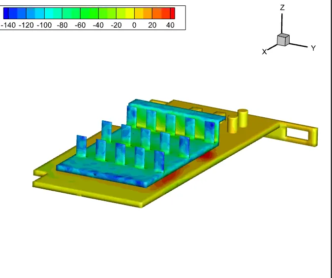
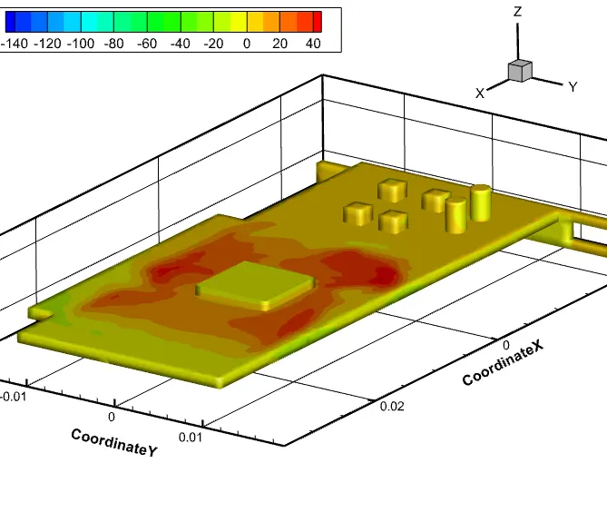
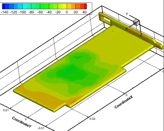
Heat transfer Contour for whole geometry, front side and backside.
3) Simulation Results for 5m/s
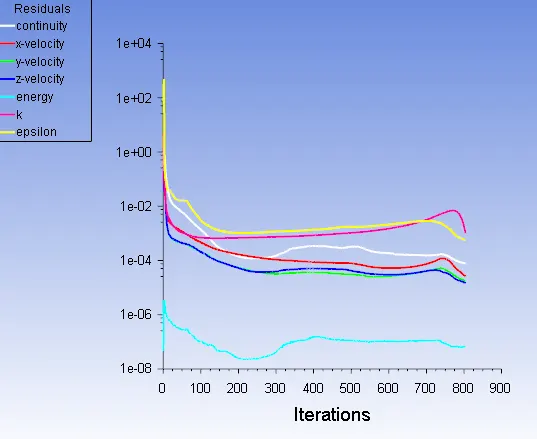
Residuals converged at 800 iterations.
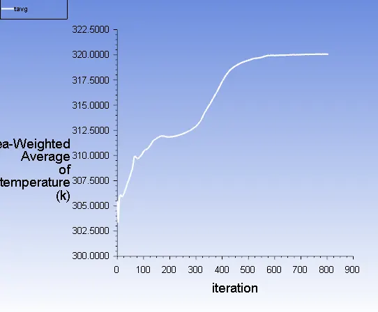
Area Weighted Temperature
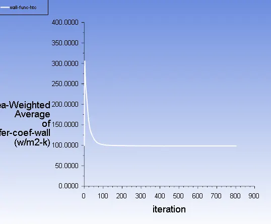
Heat transfer Coefficient
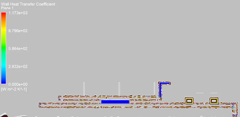
Wall Heat Transfer Coefficient
Wall heat transfer coefficient maximum value is coming as `1173W/(m^2K)`.
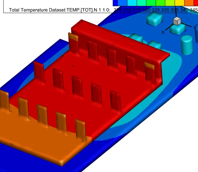
Temperature contour for 5m/s
It can be seen that fins at the front are cooler than the ones behind. This happens because the cold air first hits the front fins, it gets heated up and goes to the next fin. Hence, the next fins can't give it enough heat as the difference in temperature is lower in between solid and fluid.
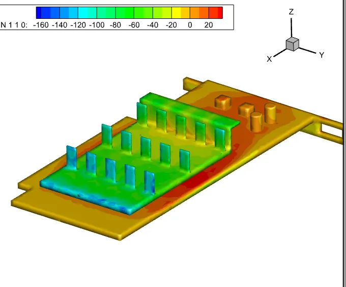
Heat Trasfer Coefficient Contour for 5m/s
In the below figure one can observe that the value of velocity increases as the heat transfer coefficient value decreases and the outer fins are cooler than inner fins. This is due to the velocity of air passing from sides being more than that at the center. and outer velocity temperature is more than the inner. The design of fins can be improved by diverting air near inner parts.
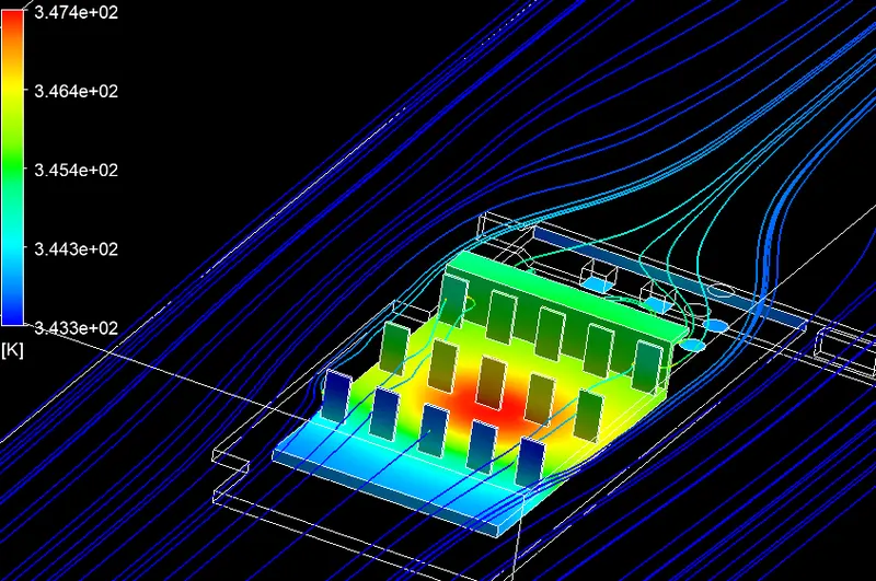
Local Temperature of fins along with temperature streamlines.
HOTSPOTS
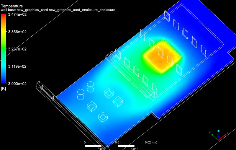
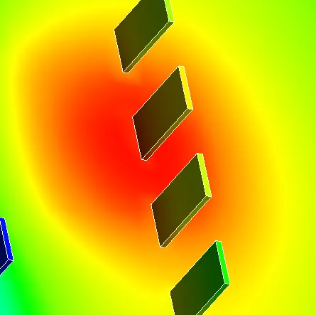
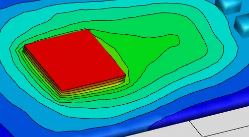
Attention must be given to identifying hotspots in the geometry for proper placement of parts and other auxiliaries. The temperature at the hotspot zone must be tried to reduce.
Recirculation Zones
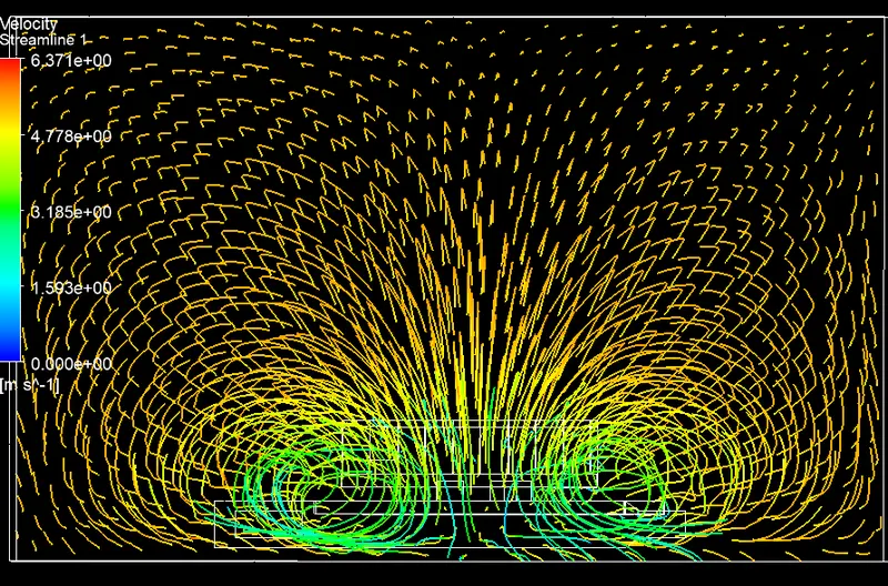
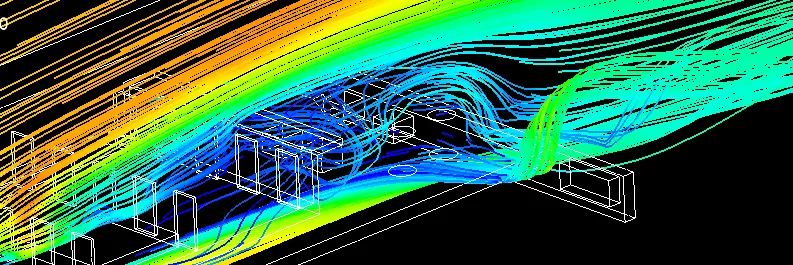
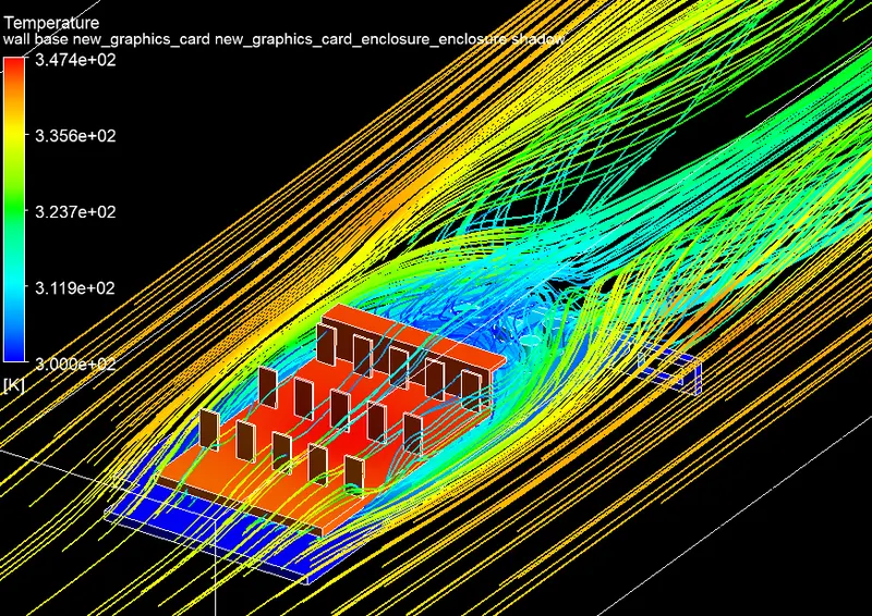
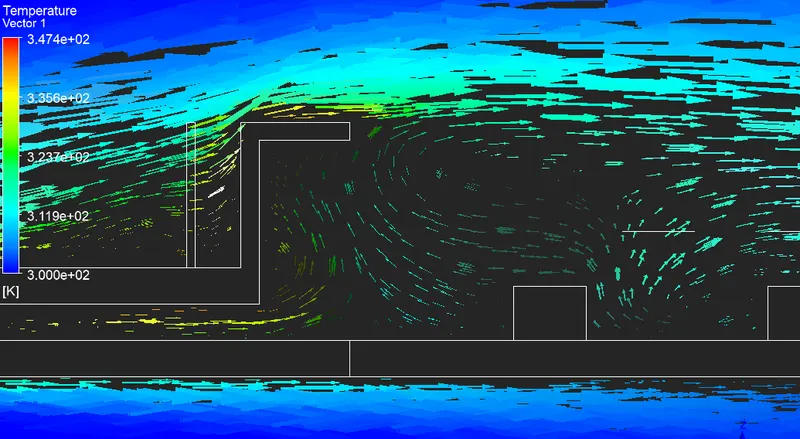
5 recirculation zones are identified in the geometry. Geometry should be tried to design in such a way to reduce recirculation zones as they will form pockets of hot air thus decreasing the cooling performance.
Conclusion
1) The heat transfer rate is directly affected by velocity. As we increase the velocity the Total temperature on the graphic card reduces. Higher velocity in a particular region means a higher Reynolds number. That’s why the heat transfer coefficient in that area is highest, which means the maximum amount of heat transfer is taking place from fluid to the solid in that region. This also results in a higher temperature of solid in that location.
2)Meshing the geometry plays an important role to capture the heat transfer in the complex geometry. The processor, which is the heat source is the potential hot spot of the graphic card.
3) Fins play a major role in the transfer of heat.
4) The base material is chosen such that it prevents the conduction of heat to the mount and provides the positions for mounting other parts.
5) Recirculation zone must be avoided due to formation of hot air pockets,
6) Hot zones must be avoided for mounting of parts.