Week 6 - CHT Analysis on a Graphics card
Objective: To perform a steady state conjugate heat transfer analysis on a model of graphics card.
introduction
The term conjugate heat transfer (CHT) describes the process which involves variation of temperature within solids and fluids, due to thermal interaction between the solids and fluids, the exchange of thermal energy between the two physical bodies is called study of heat transfer, the rate of transferred heat is directly proportional to the temperature difference between the bodies.
Conjugate heat transfer corresponds with the combination of heat transfer in solid and heat transfer in fluids, in solids, conduction often dominates whereas in fluids, convection usually dominates. efficiently combining heat transfer in fluids and solids is key to designing effective coolers, heaters or heat exchanger. forced convection is the most common way to achieve high heat transfer rate. in some applications the performances are further improved by combining convection with phase change.
Heat transfer in solids and heat transfer in fluids are combined in the majority of applications. this is because fluids flow around solids or between solid walls and because solids are usually immersed in a fluid.
Graphic card
A graphics card (also called a display card, video card, display adaptor or graphics adaptor) is an expansion card which generates a feed of output images to a display device like monitor. the graphics card is responsible for rendering an image to your monitor. it does this by converting data into a signal which your monitor can understand.
Geometry
- Download and import model in geometry.
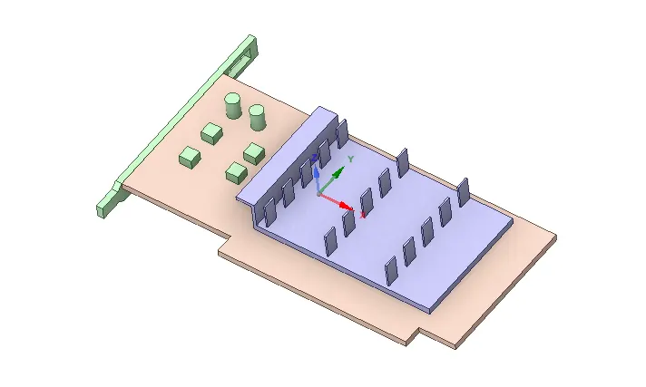
- Share topology to make sure that we get conformal mesh.
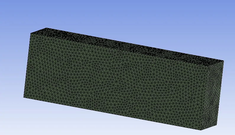
Meshing
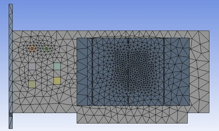
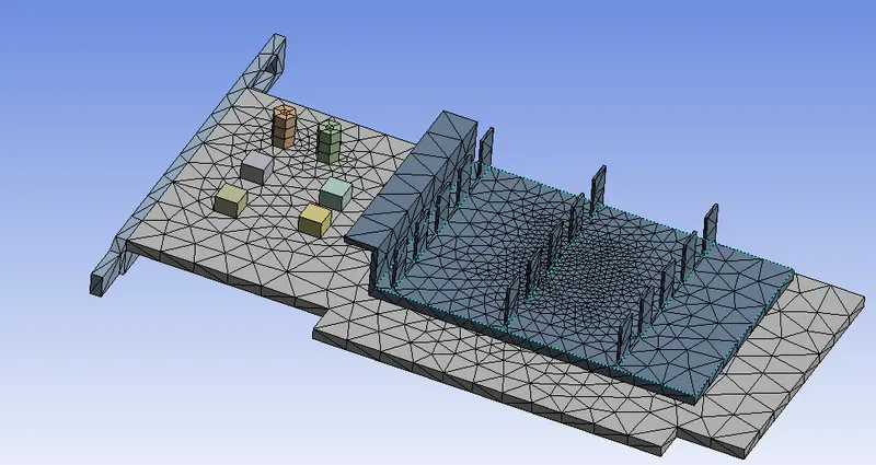
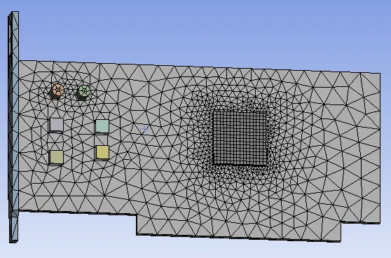
Baseline mesh
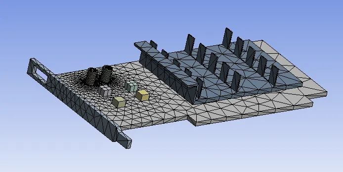
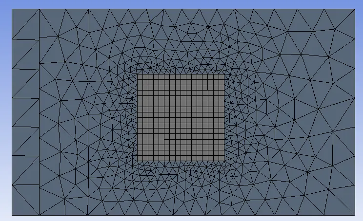
Refined mesh
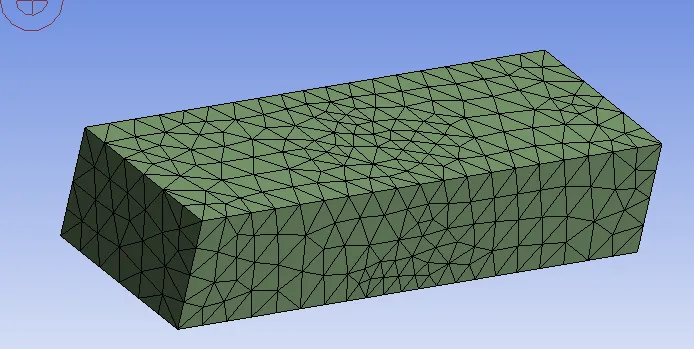
- Insert 4 body sizing and select 1 component in each of them and refine mesh by varying the element size.
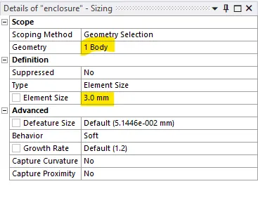
- select the body and edit the element size similarly for other bodies.
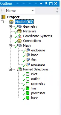
- Named selection
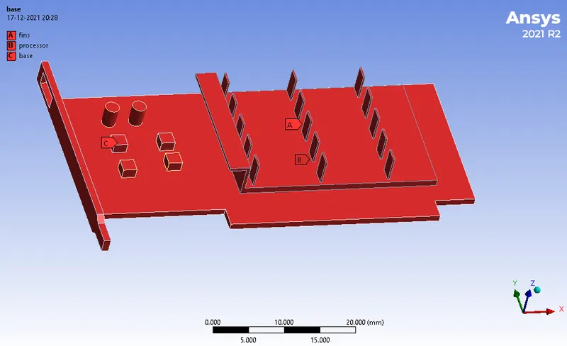
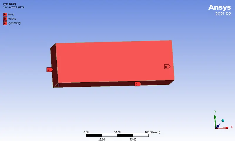
Setup
- general setup
- solver type: pressure based
- velocity formulation: absolute
- time: steady state
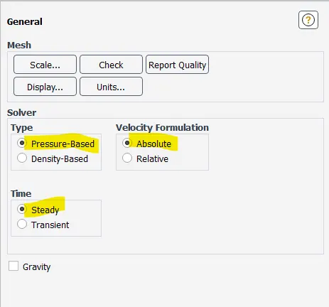
- Enable energy.
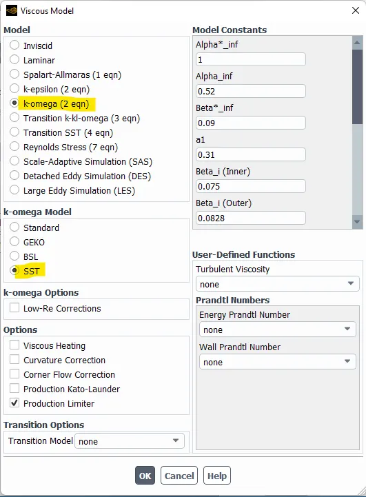
- Turbulence model: K-Omega SST
- Materials
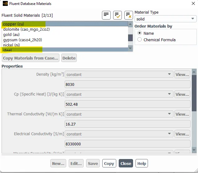
- copy solid materials from fluent data base.
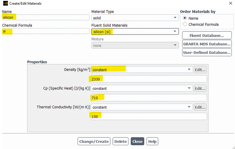
- silicon is used for manufacturing processor, since silicon is not available in fluent database. so, we copy a material and edit its properties as per silicon material.
Density
`((Kg)/m^3)`
Specific heat at constant pressure`(C_p)`
`(J/(Kg-K))`
Thermal conductivity
`(W/(m-K))`
steel
8030
502.48
16.27
Copper (Cu)
8978
381
387.6
Silicon (Si)
2330
710
150
- copy solid materials from fluent data base.
- Zones
- cell zones
- Base
- type: solid(steel)
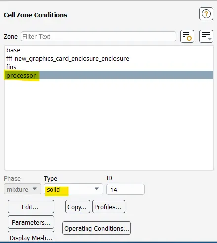
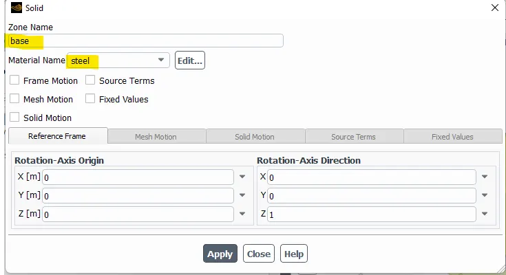
- type: solid(steel)
- fins
- type: solid(copper)
- Processor
- type: solid(silicon)
- Enable source term for processor and set value 15625000`W/m^3`.
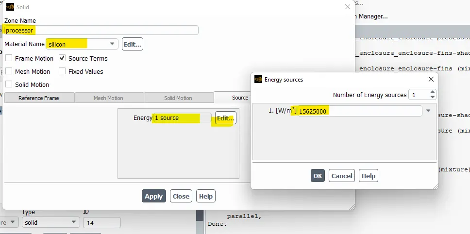
- type: solid(silicon)
- Base
- Boundaries
- inlet
- type: velocity inlet
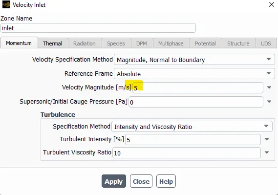
- type: velocity inlet
- Outlet
- Type: pressure outlet
- Symmetry
- type: symmetry
- inlet
- cell zones
- Report definition
- create report definition for temperature.
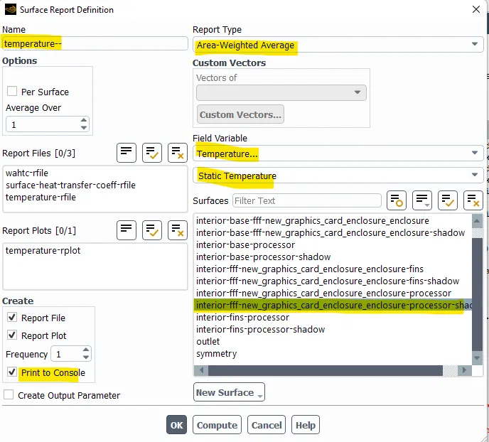
- similarly create report definition for surface heat transfer coefficient.
- create report definition for temperature.
- Initialize
- hybrid initialization.
- Create contour for temperature.
- Run simulation.
RESULTS
At velocity 1m/sec
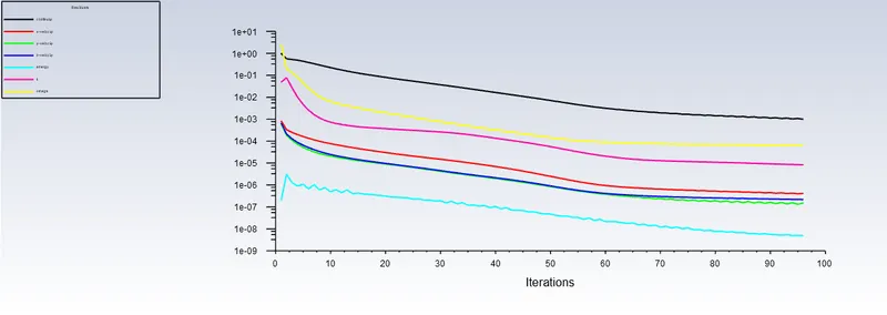
Scaled residuals
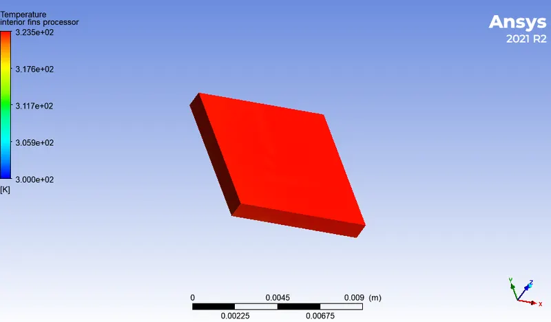
Processor
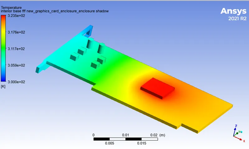
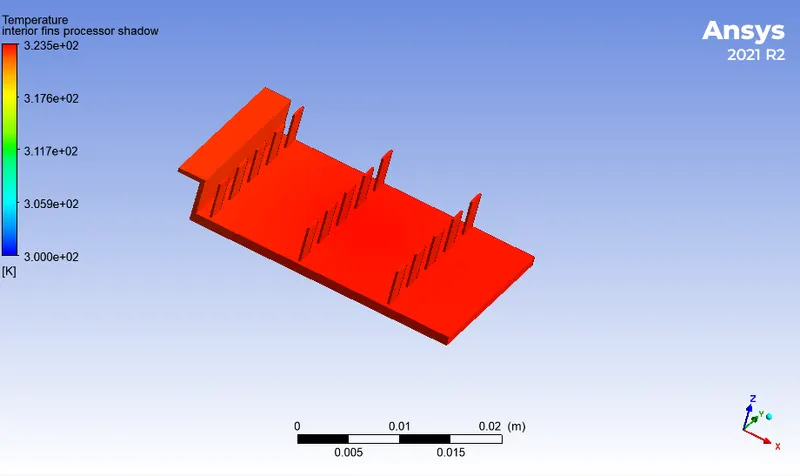
Bese with processor
Fins
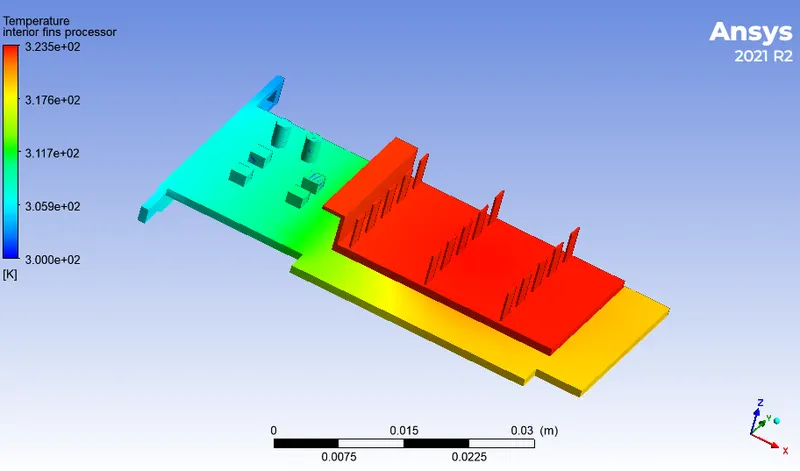
GPU
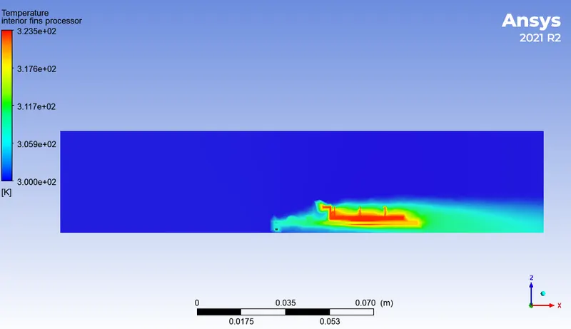
Temperature distribution inside enclosure
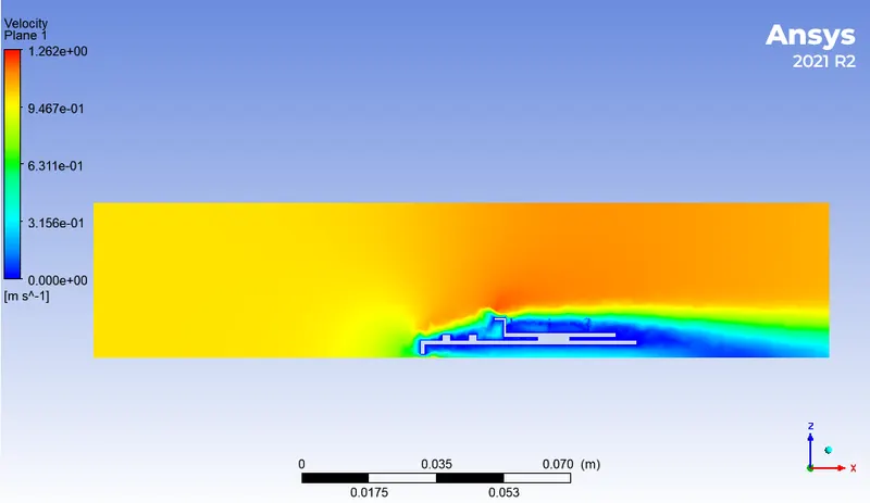
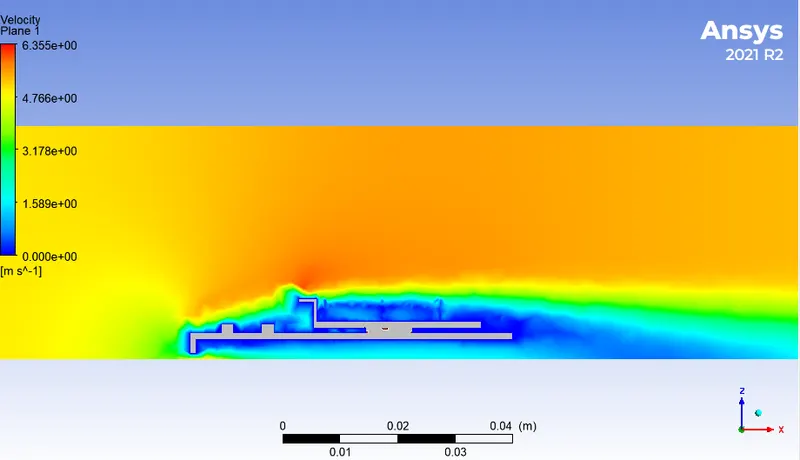
velocity contour of airflow over GPU
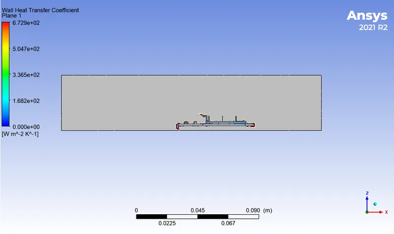
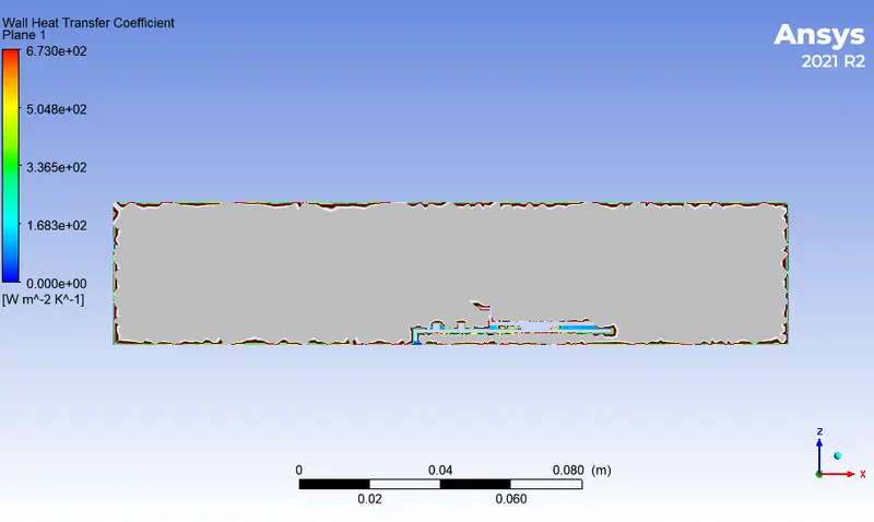
Wall heat transfer coefficient
AT velocity 3m/sec
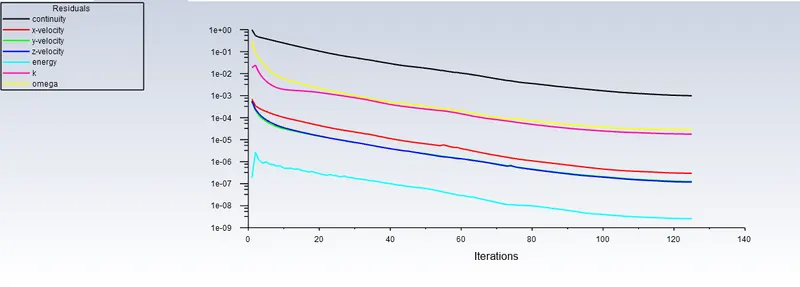
Scaled residuals
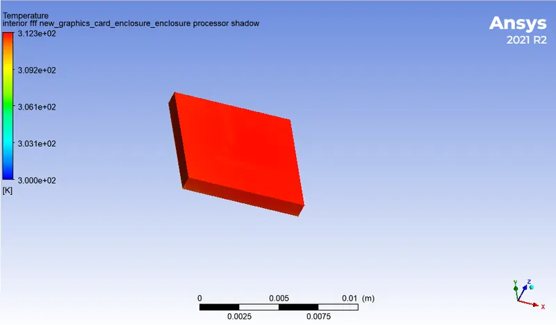
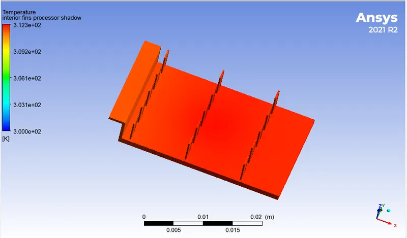
processor
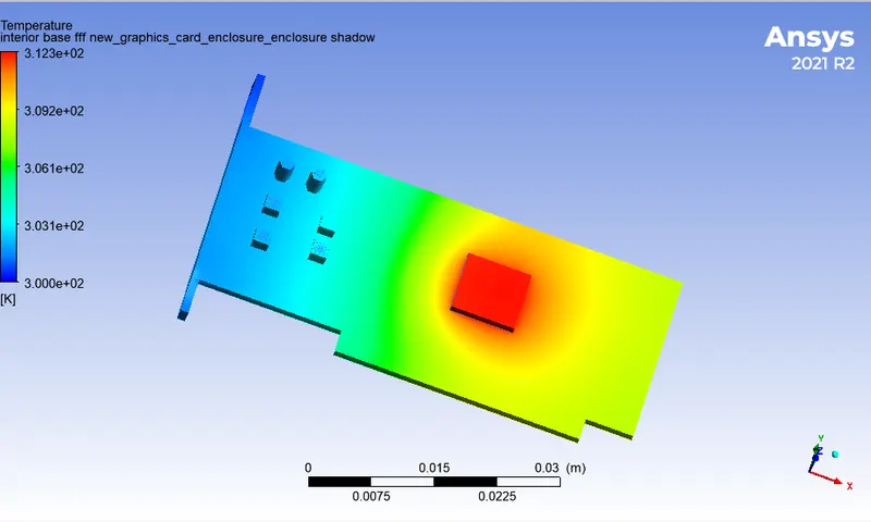
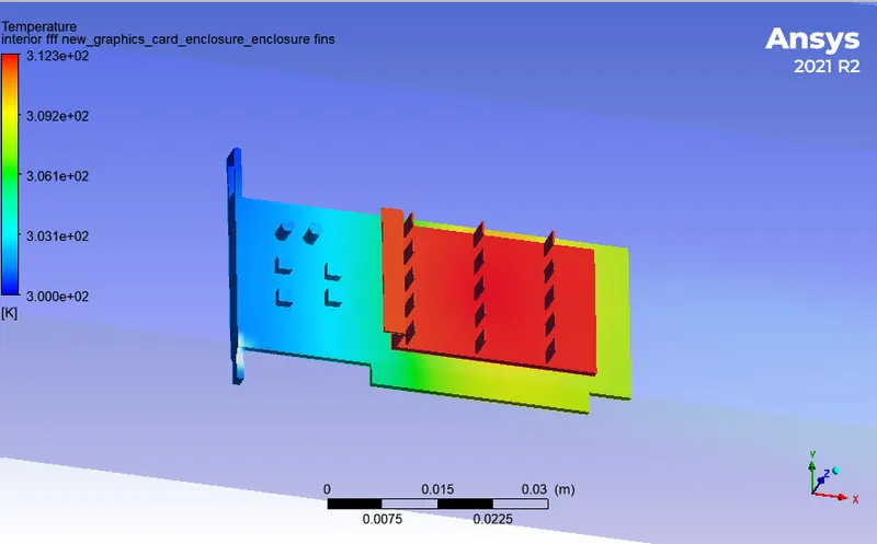
GPU
Fins
GPU
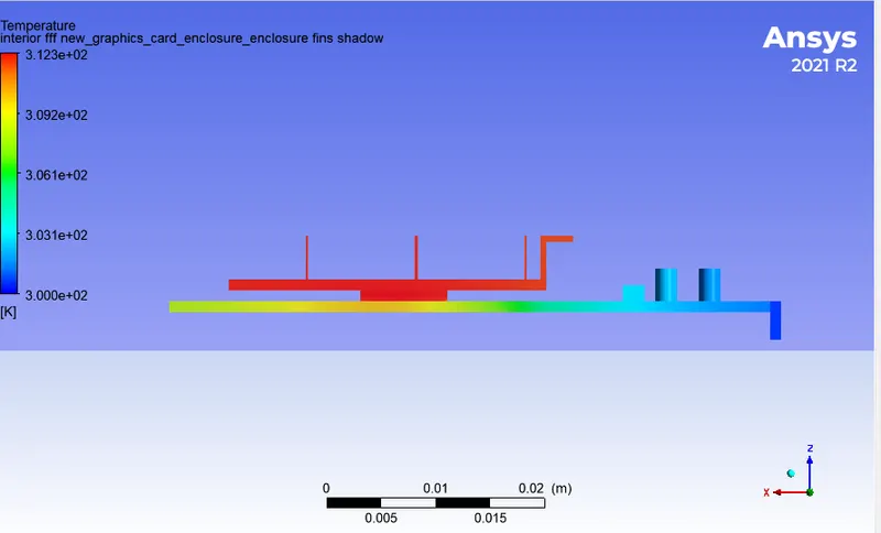
Side view
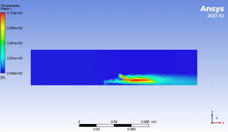
Temperature distribution inside enclosure
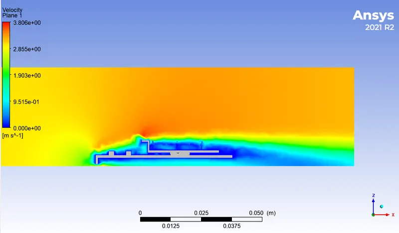
Velocity contour of airflow over GPU
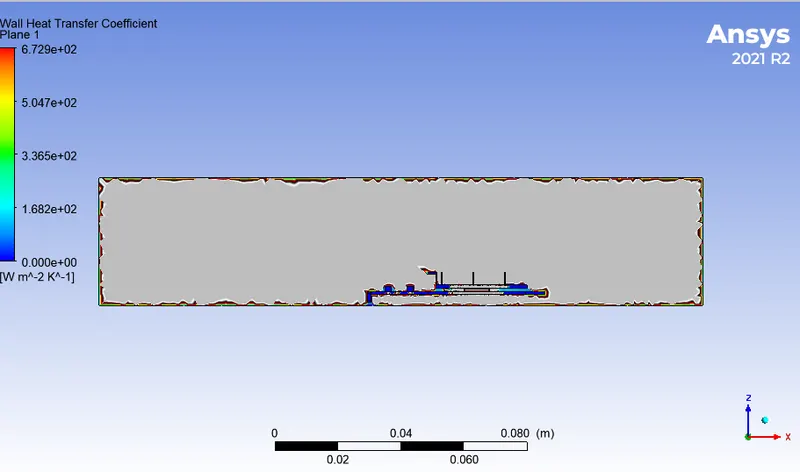
wall heat transfer coefficient
At velocity 5m/sec
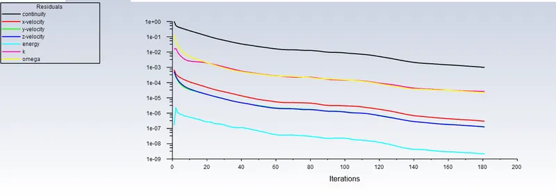
Scaled residual
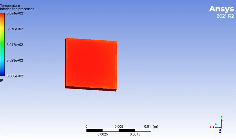
Processor
GPU
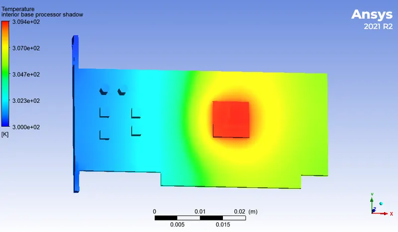
Fins
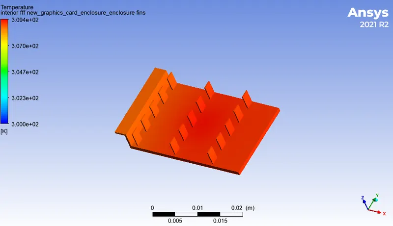
GPU
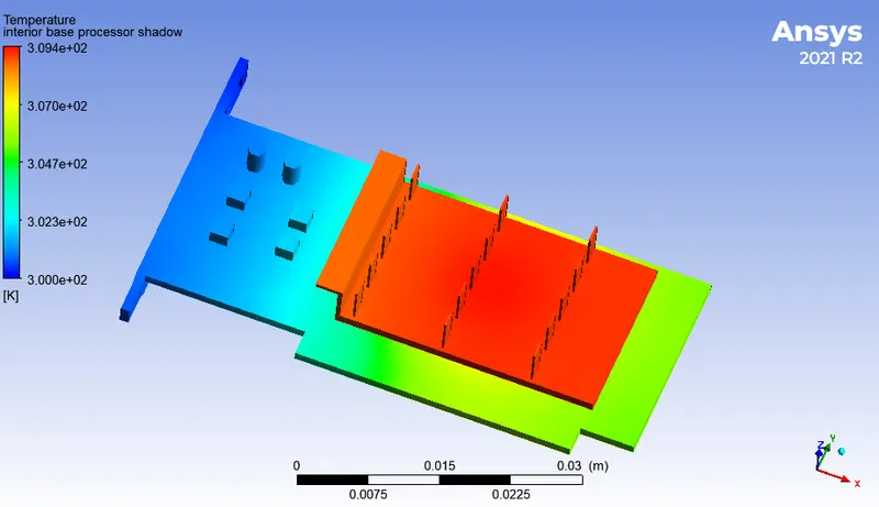
temperature distribution inside enclosue
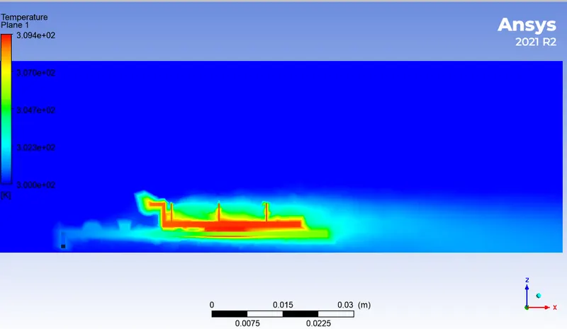
Velocity contour of airflow over GPU
Wall heat transfer coefficient
Output table
|
case |
Velocity `(m/sec)` |
Maximum temperature on graphics card (K) |
Maximum wall heat transfer coefficient `(W/(m^2K))` |
|
Baseline mesh |
1 |
323.6 |
1119.0 |
|
Refined mesh |
1 |
323.5 |
672.9 |
|
Refined mesh |
3 |
312.3 |
672.9 |
|
Refined mesh |
5 |
309.0 |
673.0 |
From the results output table we can observe that by increasing the velocity of air, processor temperature is decreasing. this is because as the velocity of flow is increased, more amount of heat is carried away by air. the heat transfer coefficient is highest in the regions which are in contact of the processor. this region is not affected by the change inflow velocity since there is no airflow present, hence the maximum heat transfer remains the same in the region exposed to the fluid flow. also we can say that refined mesh gives more accurate result compared to course mesh.
Conclusion
- The refined mesh provides the more accurate result than coarser mesh. Accuracy can be increased by increasing the no. of elements.
- The temperature of the graphic card decreases with the increase in velocity because as the velocity of flow is increased, more heat is carried away by the air, hence graphic card cooled.
- The processor is the potential hotspot of the graphic card assembly since it is the only heat generation source of the entire assembly. the temperature and wall heat transfer coefficient of the processor and other parts are influenced the heat generated by the processor. Also, the heat generated by the processor depends on its workload. higher the workload higher the heat generated by the processor.