Week 6 - CHT Analysis on a Graphics card
Aim : In this project our aim to find the possible way to reduce the heat which is developed in the electronic equipment, the heat generating component it the processor , since it generates a high heat it has to be cooled such that we can safe guard the soldering of the electronic circuits and hence preventing a fire hazard or a short circuit .Hence a cooling system has to be remove the heat by using a fan, since a forced convection removes the heat quickly. For that purpose we use three different velocities with which is air is fed across the processor and find the max temperature in the processor and also the heat transfer coefficient of the processor.
Methodology: We are aware that processor is made from different materials, for the simplicity of the case we take aluminium since it has good thermal conductivity and transfer heat to the fin base above it. The fin bas consists of fins which are rectangular in shape. The fins are extended surfaces for the purposes of improving the contact area and hence heat transfer coefficient, hence helps in losing the heat quickly.
The fins base are attached to the processor typically by means of thermal paste has the same thermal conductivity of fin base .The same thermal conductivity of the paste has been chosen to avoid the detachment due to the thermal expansion.
We have assumed that the processor is utilizing the electric power of 5 W out of which 3 W is dissipated in the form of heat, this heat has to be cooled quickly to maintain the temperature below the maximum operating temperature of the computer.
The fins are assumed to be of aluminium material, since aluminium has good thermal conductivity, and with the extended cross section area it can contact the stream of air, and cooling the computer.
We have also assumed other solid electronic components as aluminium for simplicity, the main area of importance is the processor and fins base above it. We expect that as we increase the air flow across the fins and processor the max temperature of the processor would be reduced and we validate it with our results.
For the improvement of heat transfer we also take the turbulence into consideration, since there are many obstruction in the flow path, the flow is not laminar hence it results in a turbulent flow in a realistic environment. Hence our usage of turbulent model for this simulation is to mimic the actual case.
Since our focus is to find out the final temperature of the processor a steady state simulation is used
Procedure:
The step by step procedure for this simulation is done as the following steps
- Space Claim
- Meshing
- Setup
- PostProcessing
- Spaceclaim
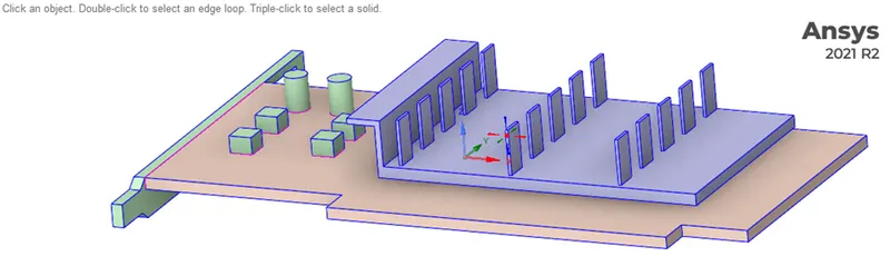
Parts of the geometry
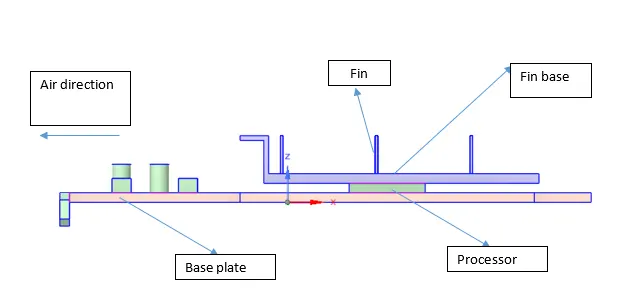
The above figure shows the various components and the direction of the air
the topology was shared by using the properties

2. Meshing
Firstly loading the geometry into the meshing, and naming the faces and bodies for our convienience in the below manner
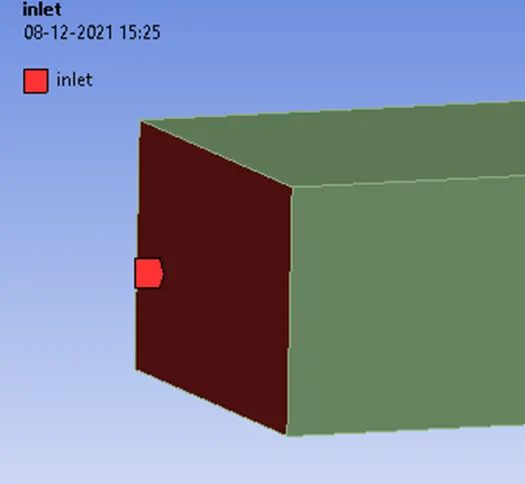
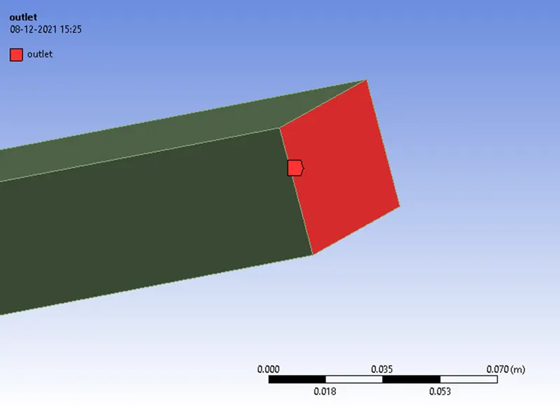
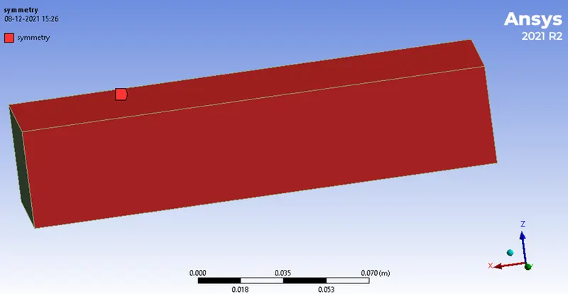
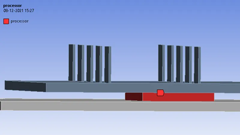
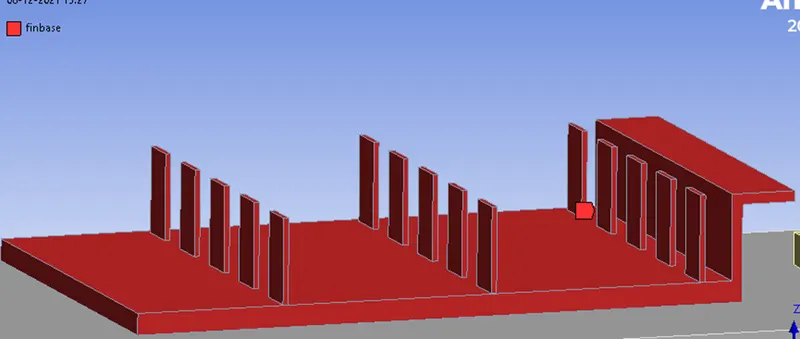
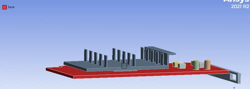
and by applying the body sizing for fin base and processor , the mesh is generated
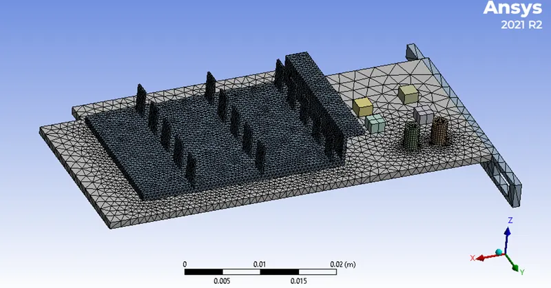
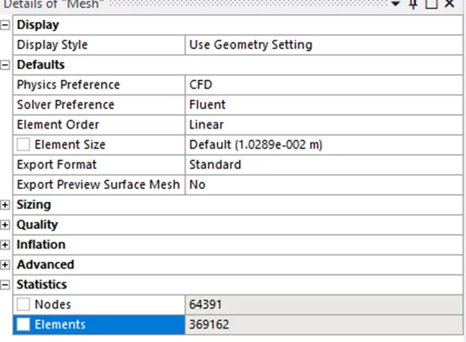
The element size and the number of elements are given below
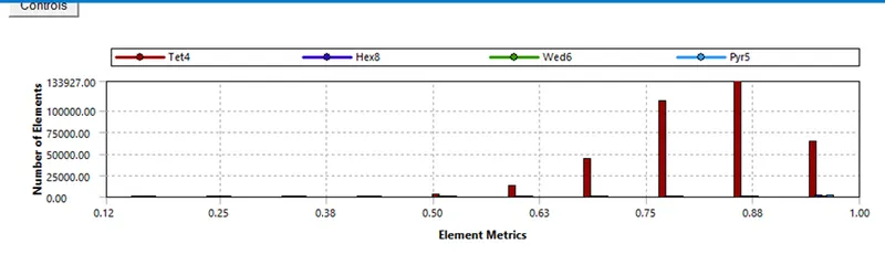
The quality of the mesh
The generated mesh isnow sent to the fluent for the simulation.
3.Setup
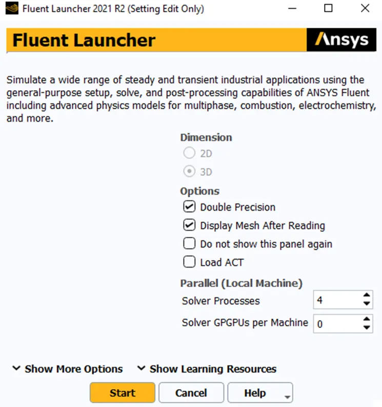
By using the parallel computing and double precision , and using a steady state and pressure based with using the energy equation and for the turbulence selecting the k epsilon model
we move further to selecting the zones and applying the materials to them
a. processor
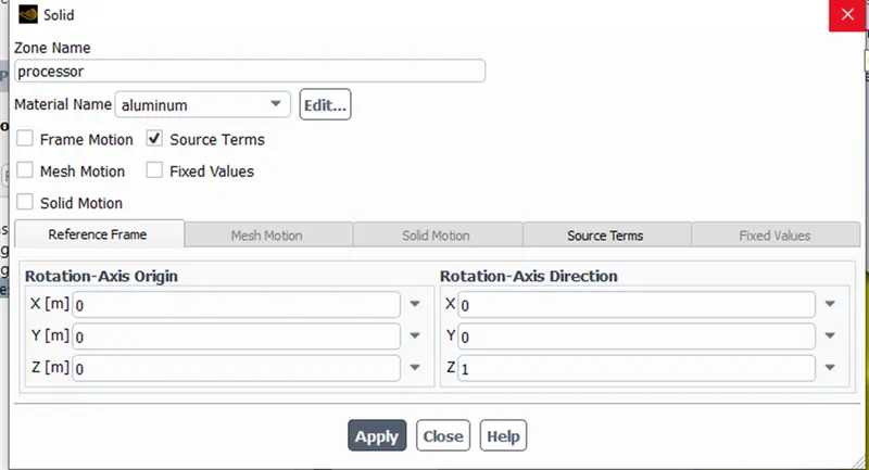
For the processor we model it as a source term and selecting aluminum as the material,
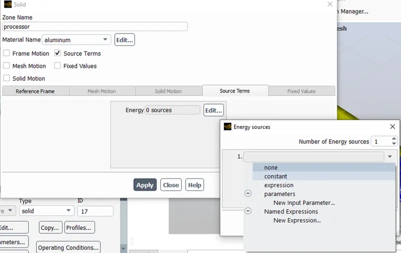
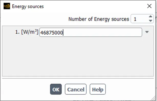
By selcting the number of sources as 1 and selecting constant from the drop down list and substituing the value of heat released per unit volume , which is calculted by
volume of the processor =`64 -mm^3`
The wattage of heat dissipated from the processor is `3 W`
`3 /(64 *10^-9) -(W/m^3)`
that gives us 46875000 W/m3
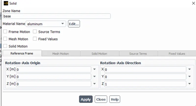
For the base we selct aluminium as the material similarly for all the other components except for enclosure
Fin base and the other components in the graphics card
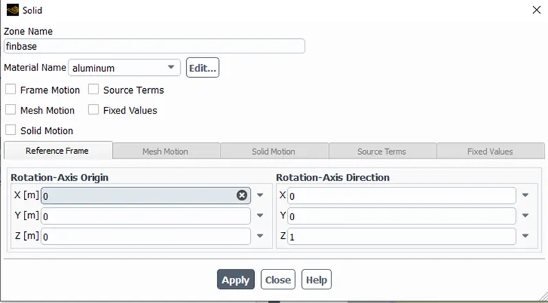
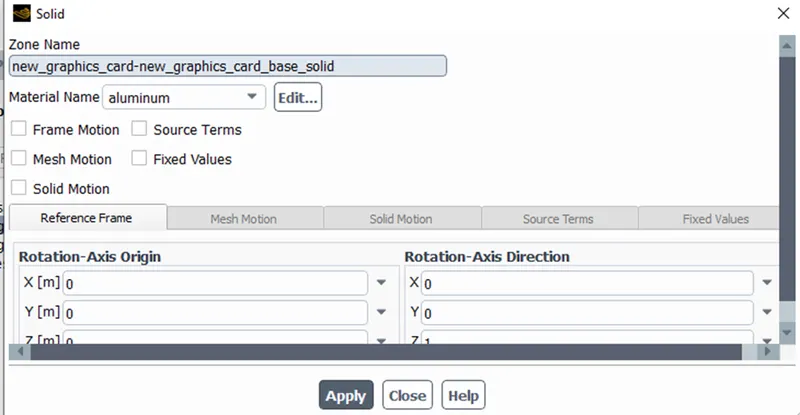
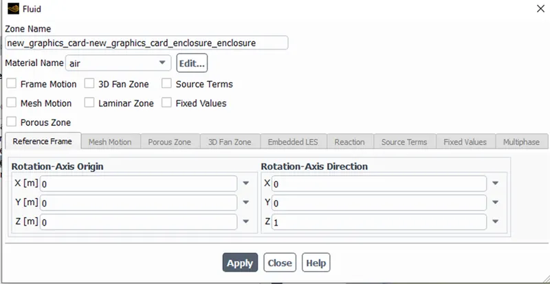
Enclosure is the fluid domain we select it as fluid and the air is assigned as the material name
Boundaries
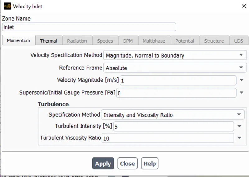
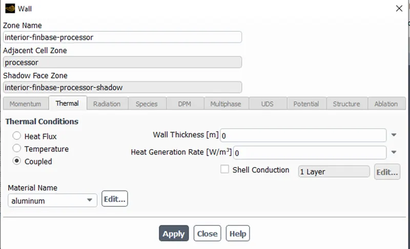
For the boundaries we select the enclosures entry as inlet and assign the velocity as required for the case , and for the thermal boundary we consider it as coupled , that is both convection and conduction are taking place.Similarly for all the other walls inside the enclosure we select coupled.
Reports
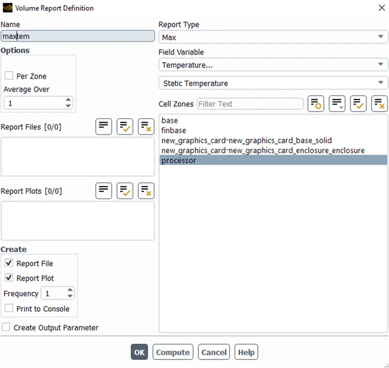
for the report definition we find the maximum temperature of the processor ,
Initialization
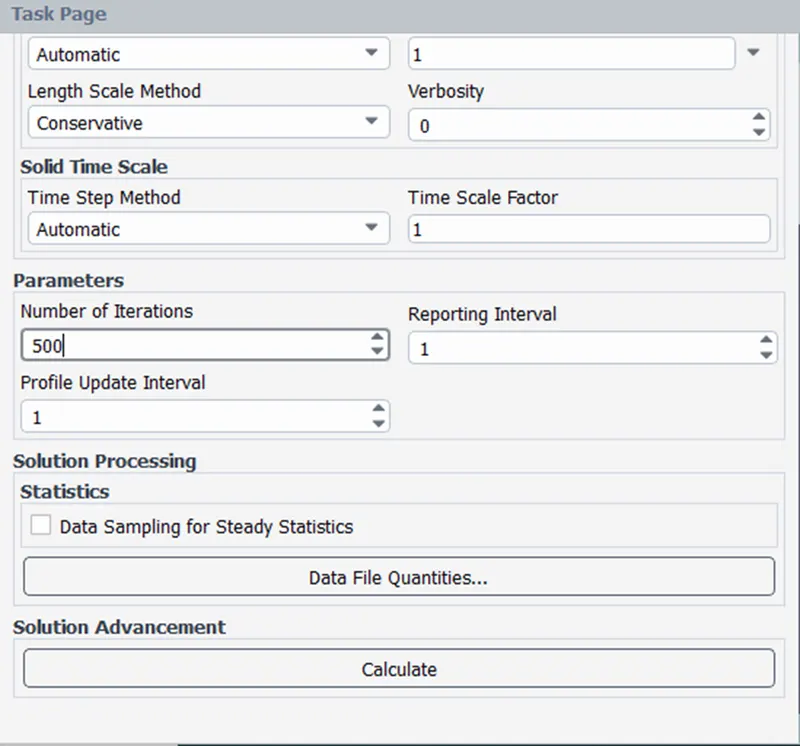
We select a hybrid initialization and and run it for 500 iterations, and observe the following reports.
Case 1 Results
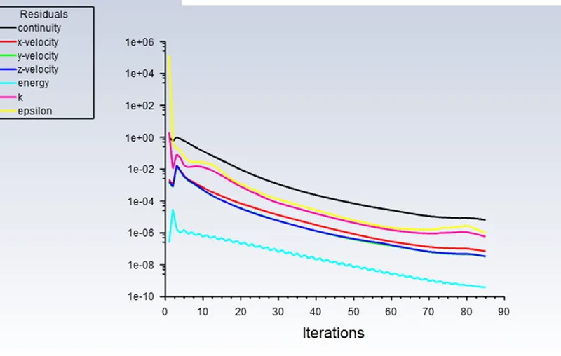
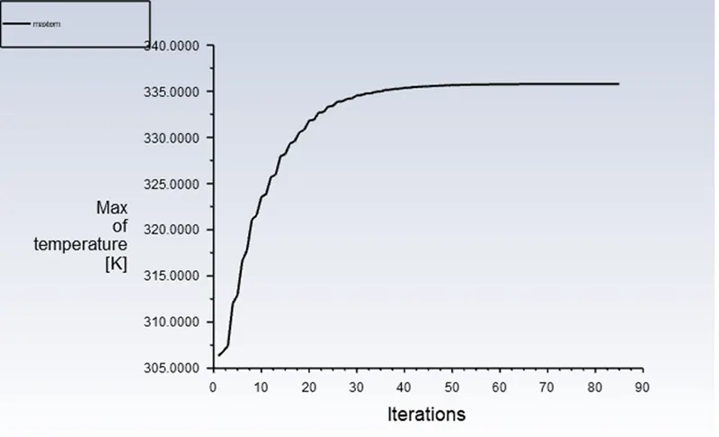
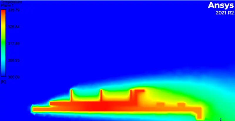
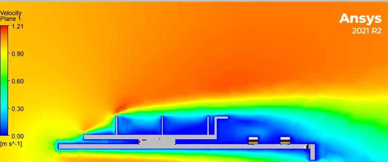
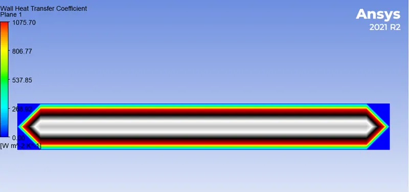
In the case 1 we run the simulation with inlet velocity of 1 m/s are following results and residuals were obtained
Residuals Max Temperature
Temperature
Velocity
Heat transfer coefficient of the processor
Case 2 Results
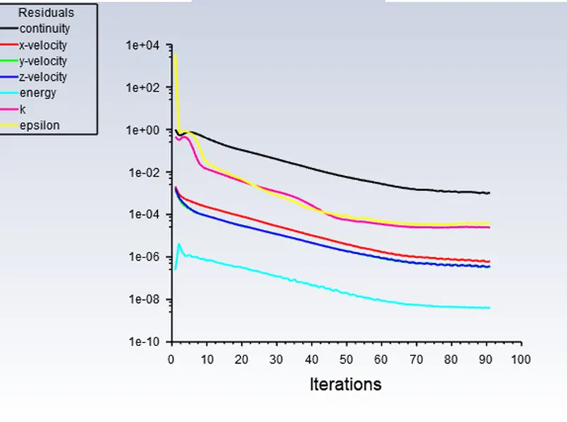
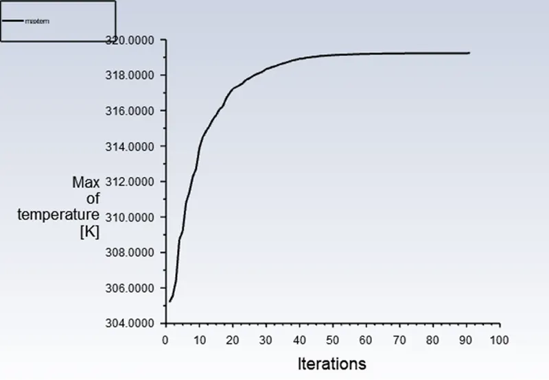
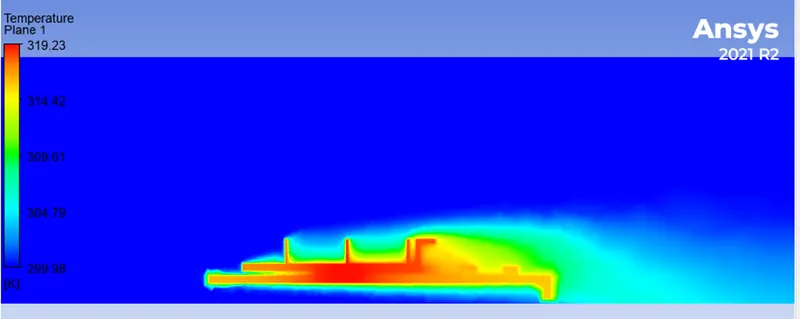
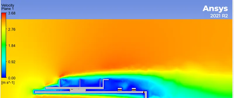
In the case 2 we run the simulation with inlet velocity of 3 m/s are following results and residuals were obtained
Residuals Max Temperature
Temperature
Velocity
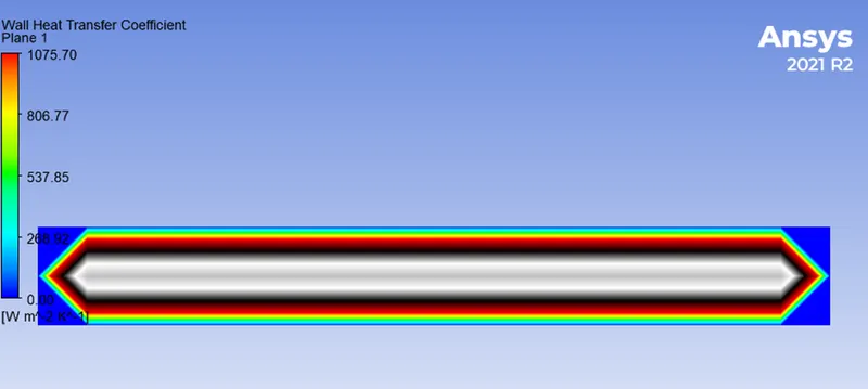
Heat transfer coefficient of the processor
Max temperature of the processor

Case 3 Results
In the case 2 we run the simulation with inlet velocity of 5 m/s are following results and residuals were obtained
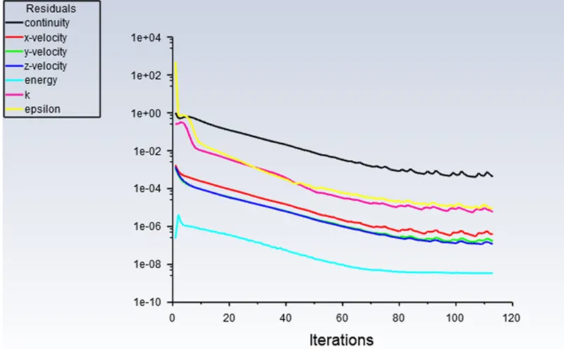
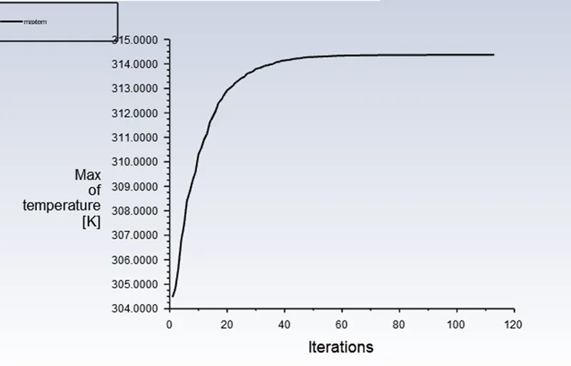
Residuals Max Temperature
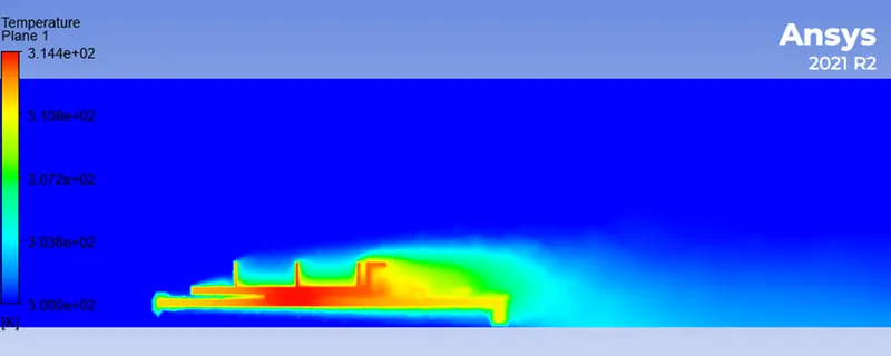
Temperature
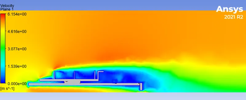
Velocity
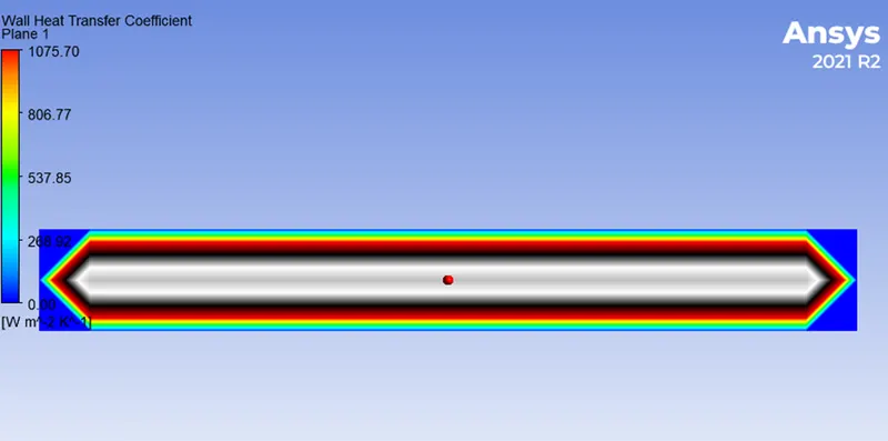
Heat transfer coefficient of the processor
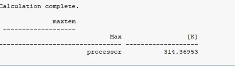
Max temperature of the processor
Conclusions
- The convergence criteria have been confirmed by seeing the maximum temperature of the processor with resoect to iterations, and iterationa have been stopped when the Steady behavior of maximum temperature has been achieved.
- We have observed that as the velocity increases the temperature of the processor decreases,Also the heat is uniformly distributed throughout the fins base and all the electronic components evenly.
- Since due to the thermal conductivity is same for all the solid component the effect of diffusion from the processor to other components is same,But the fins which are above the processor are exposed to higher temperatures than other rows of fins , it is observed that a hotspot region is created at the centre row fins.
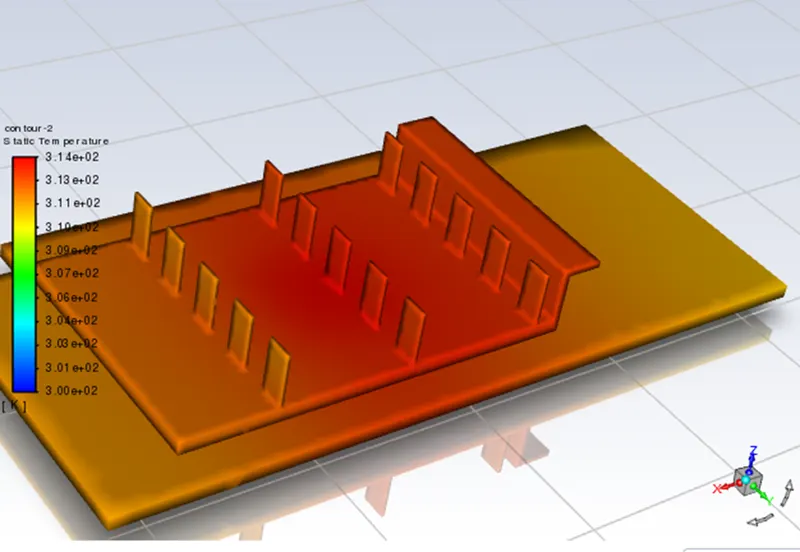
- Since the heat transfer coefficient is dependent on many parameters in a convection, a non-dimensional analysis is used for this calculation, and It is also observed that the fins due to it cross section, helps to remove the heat quickly from the processor that is seen by the temperature plot.
- Overall we can say that, cooling efficiency can be decided by velocity of air supplied and type of fin materials and number of fins mounted.
- If the number of fins mounted is increased we could have seen much amount of heat reduction hence resulting in reduced temperature in the processor.