Week-6 Challenge: EV Drivetrain
Challenge Objective:
- 1.To study about the Power Converter circuits are employed in electric and hybrid electric vehicle.
- 2.To find out the study state speed of the given EV with 70% of duty cycle.
- 3.To develop a mathematical model of an DC motor with the given equation using Simulink.
- 4.To Refer and explain the topic of Induction Versus DC brushless motors.
Answer#1
Power converters in EV
Energy storage or supply devices vary their output voltage with load or state of charge and the high voltage of the DC-link create major challenges for vehicle designers when integrating energy storage / supply devices with a traction drive. DC-DC converters can be used to interface the elements in the electric power train by boosting or chopping the voltage levels. Due to the automotive constraints, the power converter structure has to be reliable, lightweight, small volume, with high efficiency, low electromagnetic interference and low current/voltage ripple.
Three DC/DC converters topologies
- Conventional step-up dc-dc converter
- Interleaved 4-channels step-up dc-dc converter with independent inductors.
- Full-Bridge step-up dc-dc converter
DC/DC converters for electric vehicles
The different configurations of EV power supply show that at least one DC/DC converter is necessary to interface the Fuel Cells, the Battery or the Super capacitors module to the DC-link.
In electric engineering, a DC to DC converter is a category of power converters and it is an electric circuit which converts a source of direct current (DC) from one voltage level to another, by storing the input energy temporarily and then releasing that energy to the output at a different voltage. The storage may be in either magnetic field storage components (inductors, transformers) or electric field storage components (capacitors).
DC/DC converters can be designed to transfer power in only one direction, from the input to the output. However, almost all DC/DC converter topologies can be made bi-directional. A bi-directional converter can move power in either direction, which is useful in applications requiring regenerative braking.
The amount of power flow between the input and the output can be controlled by adjusting the duty cycle (ratio of on/off time of the switch). Usually, this is done to control the output voltage, the input current, the output current, or to maintain a constant power. Transformer-based converters may provide isolation between the input and the output. The main drawbacks of switching converters include complexity, electronic noise and high cost for some topologies. Many different types of DC/DC power converters are proposed in literature (Chiu & Lin, 2006), (Fengyan et al., 2006). The most common DC/DC converters can be grouped as follows:
Non-isolated converters
The non-isolated converters type is generally used where the voltage needs to be stepped up or down by a relatively small ratio (less than 4:1). And when there is no problem with the output and input having no dielectric isolation. There are five main types of converter in this non-isolated group, usually called the buck, boost, buck-boost, Cuk and charge-pump converters. The buck converter is used for voltage step-down, while the boost converter is used for voltage step-up. The buck-boost and Cuk converters can be used for either step-down or step-up. The charge-pump converter is used for either voltage step-up or voltage inversion, but only in relatively low power applications.
Isolated converters
Usually, in this type of converters a high frequency transformer is used. In the applications where the output needs to be completely isolated from the input, an isolated converter is necessary. There are many types of converters in this group such as Half-Bridge, Full-Bridge, Fly-back, Forward and Push-Pull DC/DC converters . All of these converters can be used as bi-directional converters and the ratio of stepping down or stepping up the voltage is high.
Answer #2
Study state speed of an EV with given parameters.
Given values,
Rated Armature voltage= 72 V
Rated armature current= 400 A
Ra= 0.5Ω, KΦ= 0.7 Volt /second
Chopper Switching frequency= 400 Hz
Duty cycle 70%
The vehicle speed-torque characteristics are given by the below equation
Tv = 24.7+(0.005)w^2------1
Steady state speed :
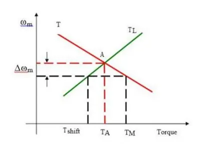
Equilibrium speed of motor-load system can be obtained when motor torque equals the load torque. Electric drive system will operate in steady state at this speed, provided it is the speed of stable state equilibrium.
Concept of steady state stability has been developed to readily evaluate the stability of an equilibrium point from the steady state speed-torque curves of the motor and load system. In most of the electrical drives, the electrical time constant of the motor is negligible compared with the mechanical time constant. During transient condition, electrical motor can be assumed to be in electrical equilibrium implying that steady state speed torque curves are also applicable to the transient state operation.
Now, consider the steady state equilibrium point A shown in figure below
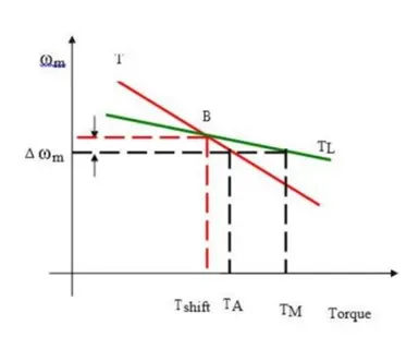
Now consider equilibrium point B which is obtained when the same motor drives another load as shown in the figure.
A decrease in speed causes the load torque to become greater than the motor torque, electric drive decelerates and operating point moves away from point B.
The torque equation of DC machine
T = (Vk/R) – ( K^2W/R)-----2
T - Torque,
V - Armature Voltage
R - Armature winding Resistance
W - Speed of the Motor rad/sec
Compare the both equations 1&2:
24.7 + 0.0051W^2 = ((Vk)/R) – ((k^2)W/R)
24.7 + 0.0051W^2 = (72x0.7x0.7)/0.5 – (0.7^2/0.5)W = 24.7 + 0.0051W^2
70.56-0.98W = 0.7 + 0.0051W^2
W^2 + 192.15W – 8992.15 = 0
W^2+192.15W=8992.15
Quadratic Equation in Standard Form: ax^2 + bx + c = 0
Quadratic Formula: x = −b ± √(b2 − 4ac) 2a
W=-38.95 rad/sec
So, the study state speed of a DC motor with 70% of duty cycle is = 38.95 r/s or
(38.95 x 9.552) = 372rpm.
Answer #3
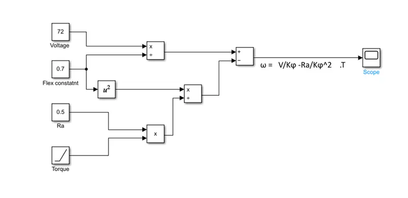
Given equation: ω = V/Kϕ -(Ra/(K^2)) .T
where,
V = Input Voltage
K = motor constant
ϕ = magnetic flux
Ra = armature resistance
T = Torque
Required blocks in Simulink:
Constant - Used to give the input constant values to the model such as Rated armature Voltage, motor constant and armature resistance
Ramp - Used to give variable input (Torque) to the model with respect to time
Square - Used to square the values
Divide - Used to divide the values, which is required in the equation
Subtract - Used to do arithmetic operations.
Product - Used to multiply the two values
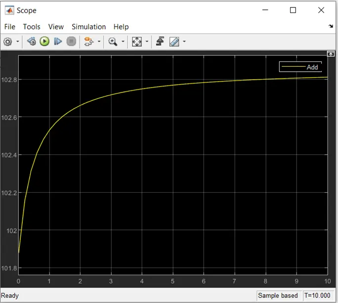
Scope - Used to see the results of the plot between torque and speed.
Simulink Module for the given equation:
The output:
Answer #4:
Induction Versus DC brushless motors by Wally Ripple,Tesla.
BLDC Motors
- With brushless machines, the rotor includes two or more permanent magnets that generate a DC magnetic field.
- In turn, this magnetic field enters the stator core and interacts with currents flowing within the windings to produce a torque interaction between the rotor and stator. As the rotor rotates, it is necessary that the magnitude and polarity of the stator currents be continuously varied – and in just the right way - such that the torque remains constant and the conversion of electrical to mechanical energy is optimally efficient.
- The device that provides this current control is called an inverter. Without it, brushless motors are useless motors.
Induction Motor
- A forerunner of the 3-phase induction motor was invented by Nikola Tesla sometime before 1889. Curiously, the stators for the 3-phase induction motor and the DC brushless motor are virtually identical. Both have three sets of “distributed windings” that are inserted within the stator core. The essential difference between the two machines is with the rotor.
- Unlike the DC brushless rotor, the induction rotor has no magnets – just stacked steel laminations with buried peripheral conductors that form a “shorted structure”.
- Currents flowing in the stator windings produce a rotating magnetic field that enters the rotor. In turn, the frequency of this magnetic field as “seen” by the rotor is equal to the difference between the applied electrical frequency and the rotational “frequency” of the rotor itself.
- Accordingly, an induced voltage exists across the shorted structure that is proportionate to this speed difference between the rotor and electrical frequency. In response to this voltage, currents are produced within the rotor conductors that are approximately proportionate to the voltage, hence the speed difference.
- Finally, these currents interact with the original magnetic field to produce forces – a component of which is the desired rotor torque.
- When a 3-phase induction motor is connected to utility type 3-phase power, torque is produced at the outset; the motor has the ability to start under load. No inverter is needed.
BLDC and INDUCTION
- The fact that induction motors are directly compatible with conventional utility power is the main reason for their success. In contrast, a brushless DC motor produces no starting torque when directly connected to fixed frequency utility power. They really need the aid of an inverter whose “phase” is maintained in step with the angular position of the rotor.
- 3-phase induction motors have great utility, they also have some severe limitations. They cannot operate from DC; AC is a must. Shaft speed is proportionate to line frequency. Hence, when used with utility power, they are constant speed machines. Finally, when operated from utility power, they have limited starting torque and somewhat limited running peak torque capabilities, when compared to DC type machines.
- Add an inverter (without any feedback control) and it becomes possible to power an induction machine from a battery or other DC source; variable speed also becomes possible simply by adjusting the inverter frequency. Still, torque performance is low compared with DC machines. Add some feedback loops such that the inverter produces the exact frequency that the motor “desires,” and the induction motor is now capable of competing with DC and DC brushless for vehicle applications.
- Both DC brushless and induction drives use motors having similar stators. Both drives use 3-phase modulating inverters. The only differences are the rotors and the inverter controls. And with digital controllers, the only control differences are with control code. (DC brushless drives require an absolute position sensor, while induction drives require only a speed sensor; these differences are relatively small.)
- One of the main differences is that much less rotor heat is generated with the DC brushless drive. Rotor cooling is easier and peak point efficiency is generally higher for this drive. The DC brushless drive can also operate at unity power factor, whereas the best power factor for the induction drive is about 85 percent. This means that the peak point energy efficiency for a DC brushless drive will typically be a few percentage points higher than for an induction drive.
- In an ideal brushless drive, the strength of the magnetic field produced by the permanent magnets would be adjustable. When maximum torque is required, especially at low speeds, the magnetic field strength (B) should be maximum – so that inverter and motor currents are maintained at their lowest possible values. This minimizes the I² R (current² resistance) losses and thereby optimizes efficiency. Likewise, when torque levels are low, the B field should be reduced such that eddy and hysteresis losses due to B are also reduced. Ideally, B should be adjusted such that the sum of the eddy, hysteresis, and I² losses is minimized. Unfortunately, there is no easy way of changing B with permanent magnets.
- In contrast, induction machines have no magnets and B fields are “adjustable,” since B is proportionate to V/f (voltage to frequency). This means that at light loads the inverter can reduce voltage such that magnetic losses are reduced and efficiency is maximized. Thus, the induction machine when operated with a smart inverter has an advantage over a DC brushless machine – magnetic and conduction losses can be traded such that efficiency is optimized. This advantage becomes increasingly important as performance is increased. With DC brushless, as machine size grows, the magnetic losses increase proportionately and part load efficiency drops. With induction, as machine size grows, losses do not necessarily grow. Thus, induction drives may be the favoured approach where high-performance is desired; peak efficiency will be a little less than with DC brushless, but average efficiency may actually be better.
- Permanent magnets are expensive – something like $50 per kilogram. Permanent magnet (PM) rotors are also difficult to handle due to very large forces that come into play when anything ferromagnetic gets close to them. This means that induction motors will likely retain a cost advantage over PM machines. Also, due to the field weakening capabilities of induction machines, inverter ratings and costs appear to be lower, especially for high performance drives. Since spinning induction machines produce little or no voltage when de-excited, they are easier to protect.
- Induction machines are more difficult to control. The control laws are more complex and difficult to understand. Achieving stability over the entire torque-speed range and over temperature is more difficult with induction than with DC brushless. This means added development costs, but likely little or no recurring costs.
Conclusion is that DC brushless drives will likely continue to dominate in the hybrid and coming plug-in hybrid markets, and that induction drives will likely maintain dominance for the high-performance pure electrics. The question is what will happen as hybrids become more electrically intensive and as their performance levels increase? The fact that so much of the hardware is common for both drives could mean that we will see induction and DC brushless live and work side by side during the coming golden era of hybrid and electric vehicles.
Conclusion:
Converters used in the EV vehicles has discussed, Study state speed of an DC machine calculated as per given parameters, Simulink model has described for a given equation and output also plotted, BLDC verses INDUCTION drives has differentiated as per author perspective.