Week -2
Challenge- #3
- Make a Simulink model of Doorbell using solenoid block with the following details:
In the above arrangement, when the switch is closed the electromagnet receives electrical power from the battery and pulls the metal arm to hit the bell producing sound.
Create a situation where the switch is closed for 2 seconds and then released. Observe the physical movement of the plunger.
Assume remaining parameters.
2. Use a thermistor to sense the temperature of a heater & turn on or turn off the fan as per the below conditions:
Temperature source: 20 °C from 0 to 10 seconds, 27 °C from 10 to 30 seconds, 23 °C from 30 to 50 seconds
Fan conditions: ON if the temperature above 25 °C, OFF otherwise
Answer: #1
Aim
Make a Simulink model of doorbell and show the Output.
Objective
Make a Simulink model of doorbell using solenoid block and observe the movement of plunger when switch is closed for two seconds.
- Model
A simplified representation of doorbell is given below
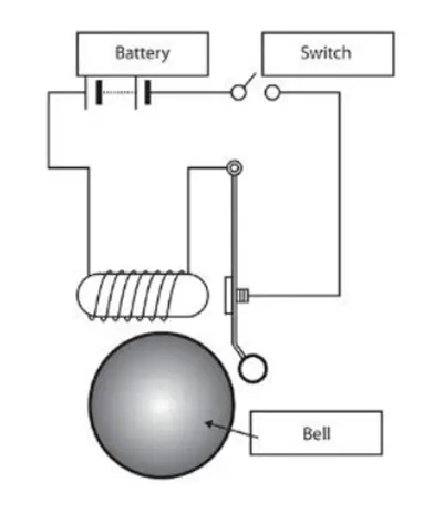
Fig.1- Door bell Model
Our primary objective is to give a signal to the solenoid block for two seconds. So the required input is given using Pulse generator block. We can customize the signal using this. An ideal translational motion sensor is used to observe the equivalent plunger movement. Arrangement of doorbell model is given below.
Simulink Model:
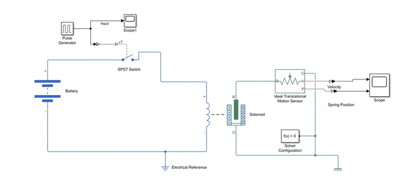
Fig.2- Doorbell Simulation model
Model Description:
1.Battery used to supply required electrical power to the circuit.
2.STSP Switch for connect and disconnect the circuit from battery.
3.Pulse generator use to produce required operating cycle input.
4.Solenoid used for convert the electrical energy to mechanical energy.
5.Ideal Translational Motion sensor used for sense the solenoid plunger movements.
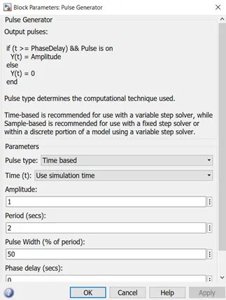
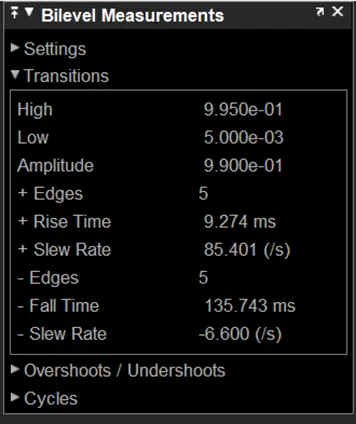
Fig.3- Pulse Input Fig.4- Output value
Signal makes the switch closed in the circuit for two seconds.
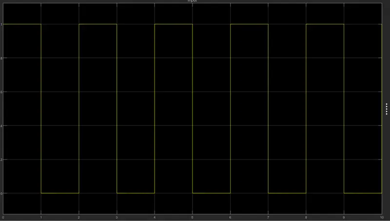
Fig.5- Pulse generator output
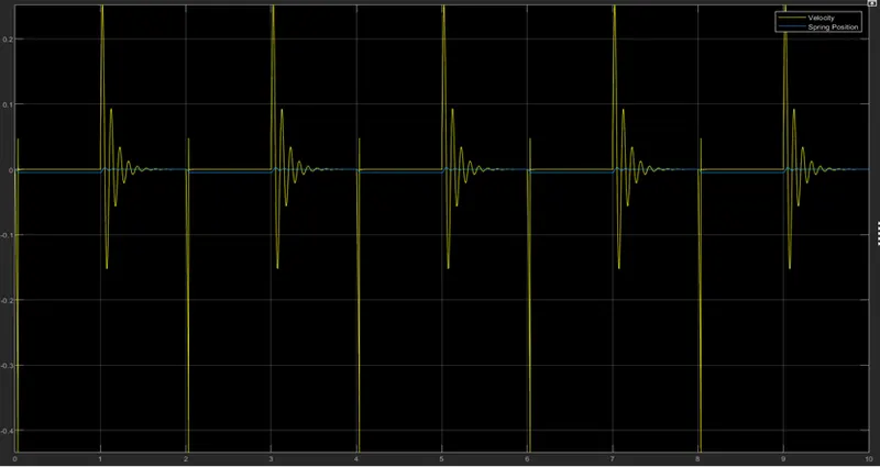
Fig.6- Solenoid Movement and Velocity
A scope block as arranged to the ideal translational motion sensor to observe the position of plunger and velocity of the solenoid, During the first 2sec the pulse generator produce the cycle switch operation same time the output of the solenoid show in the Fig.6..
Conclusion:
Solenoid based doorbell simulation blocks constructed by using Simulink and the output was plotted for the 2sec interval of the bell operation..
Answer: #2
Aim
Use a thermistor to sense the temperature of a heater and turn on or turn off as per below conditions
Temperature source: 200C from 0 to 10 seconds, 270C from 10 to 30 seconds, 230C from 30 to 50 seconds. Fan condition: ON if the temperature is above 250C, OFF otherwise.
Simulink model
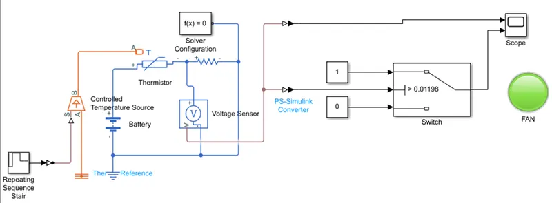
Fig.7- FAN control model
Block Models:
1.Repeating Sequence Stair
This block is used to give repeating input signal for controlled temperature source.
2.Battery
Battery is an electrical source for thermistor operation and controlled switch.
3.Voltage sensor
Voltage sensor used to find reference voltage of thermistor as output.
4.Lamp
Lamp was used Instead of FAN.
Working
This input is given to a switch which will control our dc fan. We have a condition that, fan should on when temperature is above 250C and off otherwise. So this condition is given to this switch by providing 0 and 1 as constant. Condition is again specified in switch configuration by adjusting the threshold value.
Output of the switch is given to a controlled voltage source which will provide enough voltage to the fan according to our input conditions. An ideal rotational motion sensor is connected to the dc motor to observe the motion of the fan. Motion is plotted and displayed in the scope block. It is given below.
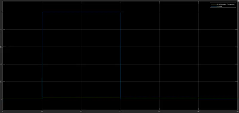
Fig.8- FAN control Output
The conditions of the temperature source is provide and the sampling time is 10 and the simulation time is 60s for that the above observation was observed.
The condition was satisfied the threshold temperature was given as 25degree Celsius and the corresponding voltage over the resistance over the resistance was found out through a display that was connected from the voltage sensor. At this time the repeating sequence stair was given only one value that is 25degree Celsius or 298K. The output from the voltage was also given into a switch which is connected to a lamp instead of FAN the light was ON and OFF as per our logical operation...
Conclusion
Automatic thermistor control for dc fan constructed by using Simulink models and the Operating sequence was saved and output was verified.