Week-6 Challenge: EV Drivetrain
1. Which types of power converter circuits are employed in electric and hybrid electric vehicle?
Charging rectifiers - AC - DC conveters
Powertrain: DC–DC converters
motor-driving inverters - DC - AC conveters
Power converters such as AC–DC, DC–DC, and DC–AC are the critical applications of modern power electronics
1. AC to DC Converters:
- The battery charging mode is classified into slow and fast charging modes based on the charging power level of the chargers
- To refill/recharge the energy storage devices, chargers are required
Conductive Charging for Electric Vehicles
- A physical connection between the power supply and the electric vehicle is involved in a conductive charging system, which consists of two main parts:
(i) AC–DC (rectifier) converter
(ii) a DC–DC converter.
- There are two types of conductive chargers available in the EV market:
(1) onboard chargers
(2) offboard chargers.
- Onboard chargers are installed inside of the electric vehicle.
- On the contrary, offboard chargers, like refueling stations, are established outside the EVs
1.Onboard Charging
- Onboard charging is the best-suited solution for the regular charging of EV users
- A conductive charging system involves a physical connection between the power supply and the electric vehicle
- An onboard charger reduces most of the time by providing independent charging features because it can be directly connected to the AC grid, providing a universal charging station solution
- This is since EVs can be charged in any residential area with 240 V voltage and a 30 A current rating
- In the following sections two popular topologies such as
- To provide isolation between the vehicle and the grid, a high-frequency transformer is utilized with a series LC/LLC resonant topology and a phase-shift modulation topology in onboard chargers
a. Phase Shift Modulation Topology
- The most popular charging converter in high-power appliances is the isolated phase-shifting-based full-bridge converter (PSFBC)
- A phase-shifted full-bridge converter provides various desirable advantages over other charging converters, such as simple control techniques, low current stress on devices, etc
- Moreover, the phase-shift modulation topology provides an alternative solution for a wide-range charging operation
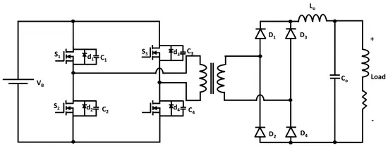
- The isolated PSFBC has two operation stages: the DC–AC converter (inverter) stage with a high-frequency transformer, and the AC–DC rectification stage
- As shown below figure, both stages consist of four power-switching elements to make a full-bridge like a conventional full-bridge converter
- The isolated phase-shifted full-bridge converter has ten working modes
b. Isolated Full-Bridge LLC Resonant Converters
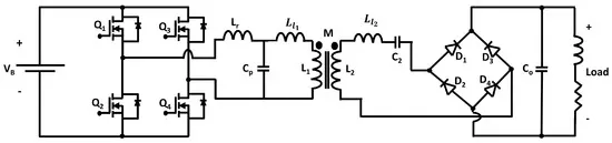
- In the EV charging stage, another powerful converter, the full-bridge LLC resonant converter, can be used, which can achieve maximum efficiency as an EV charger
- The converter is depicted in below figure, which can perform a full range of zero voltage switching for the power switching devices and high efficiency at high voltage operation
- Moreover, there is no reverse recovery current, and the rectifier diodes do not face any oscillation voltage due to the sinusoidal current waveform of the FB-LLC shape
- The isolated FB-LLC converter has seven operational modes with five working stages
2.Offboard Charging
- Offboard charging can reduce the impact of EVs on the grid with proper planning and managing peak demand
- A fast charger is required to mitigate the refueling problem, which requires more time for refueling/recharging, fewer charging stations, and a lower driving range
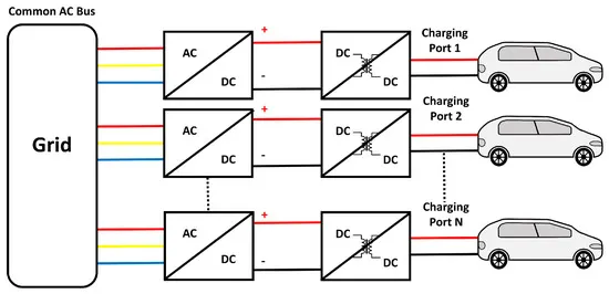
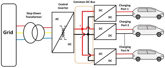
- The fast-charging architectures are usually classified into two categories:
(i) common AC-bus architecture
(ii) common DC-bus architecture
- In the typical AC-bus architecture, each fast charger consists of individual AC–DC conversion stages with a high-frequency transformer
- On the other hand, the typical DC-bus architecture consists of one central AC–DC conversion stage with a low-frequency transformer
- Several types of AC–DC converter topologies for fast charging have been investigated
- Among them,three-phase bridgeless boost rectifiers are commonly utilized in offboard charging stations
Three-Phase Bridgeless Boost Rectifier
- In EV applications, three-phase bridgeless boost rectifiers are conventionally utilized as the interface between the charging section of EV and the three-phase power supply of the grid due to their capability of converting three-phase AC into DC
- Among several types of PWM rectifier topologies, three-phase voltage source PWM rectifiers (i.e., three-phase bridgeless boost rectifiers) are widely utilized in electric vehicle applications and power generation due to their good voltage regulation, high efficiency, small input current, and output voltage filters size, and fast switching
- Hence, low-frequency harmonics can be quickly suppressed due to the high switching frequency
- The unity power factor can be obtained with the most popular pulse-width modulation (PWM) rectifier topology
- The three-phase bridgeless boost rectifier, which takes advantage of the power factor correction (PFC) boost converter
- As the name suggests, this rectifier can boost or step up the output DC voltage and is capable of bidirectional power flow with the regenerative braking of the electric vehicle, which increases the battery efficiency
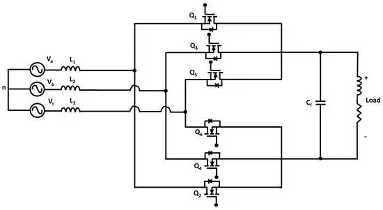
- Each phase of the three-phase bridgeless rectifier consists of one coupled inductor, which serves as the ac-side filter, and two switches
- The parallel capacitor Cf at the output side acts as the DC-side filter, which filters out the output voltage ripples
- There are six modes in the three-phase bridgeless boost converter operation, and during each mode, two switching devices are conducted
- The switching sequences of the switches determine the charging and discharging of the inductors L1, L2, and L3
2.DC–DC Converter
- For driving electric vehicles (EVs), a particular voltage level is required; otherwise, the device can be destroyed if the power is more significant than its required operating power or the device won’t be able to run if the power level is deficient. A DC–DC converter is utilized to mitigate the limitation
- Generally, the voltage level of the battery storage and supercapacitor (SC) in electric vehicle (EV) topologies are around 250–360 V and 150–400 V, respectively, and the required operating voltage of an electric motor is about 400–750 V, which is much higher than the voltage levels of batteries and SCs
- Hence, a high step-up voltage DC–DC converter is required for EV powertrains to increase the voltage level of the battery and SC
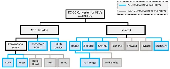
- Classification of DC–DC converter topologies is depicted below figure where light-bluer highlighted topologies are well-suited for EV powertrains due to their performance characteristics
- In comparisons between different DC–DC converter topologies have been investigated and reviewed regarding voltage-boosting techniques, applications, and efficiency.
2.1. Conventional Boost DC–DC Converter (BC)
- A conventional step-up or pulse-width modulation (PWM) boost converter is depicted below, which consists of a DC input voltage source Vs., energy storage element (i.e., inductor and capacitor), controlled switch (MOSFET, IGBT, etc.) Q, diode D, filter capacitor C, and load (electric motor)
- In a boost DC–DC converter, the output voltage is always more significant than the input voltage, hence the name “Boost”
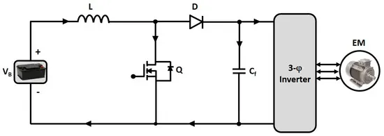
- The conventional boost converter has several merits, including simpler circuitry, lower cost due to fewer component counts, filtering and reducing electromagnetic interference efficiently, and high efficiency
- Despite many merits, this converter cannot achieve high voltage gain; extra protection requires to protect the circuit from short-circuit, and the power-switching devices require a parallel arrangement for handling high power, and the system is quite large in volume and heavily weighted because the large capacitor that is used to filter out the output voltage ripples
- To maintain a constant output voltage despite changes in input supply, designing a high-performance control system for DC–DC converters is very difficult due to the nonlinearity such as bifurcation, multiple equilibrium points, periodic behavior, and chaos of the converter
- Controllers can be of two types: voltage mode controllers, and current mode controllers. Current mode controllers are widely utilized for DC–DC converters due to their several benefits
- In , several state-of-the-art control system design methods, such as sliding mode control (SMC) , model predictive control (MPC) , intelligent fuzzy logic/control system , fractional-order proportional-integral-derivative (FOPID) control systems were proposed for conventional DC–DC boost converter topologies to mitigate these problems
- The SMC method has invariance to internal parameter variations, insensitiveness to external disturbances, fast transient response, and can improve the robustness quickly against nonlinear uncertainties; the MPC can easily consider the state variables/input constraints in the design procedure and control the conventional DC–DC converter
- The fuzzy logic-type PID control methods are generally utilized due to their effective, simple, practical, and easily tuned capabilities
- In a fractional-order PID (FOPID) control method was proposed and verified via experimental studies, which showed that the control system can provide a faster recovery time and less overshoot for a DC–DC boost converter.
2.2. Interleaved Four-Phase Boost DC–DC Converter (IBC)
- The interleaved boost converter comprises a parallel connection of boost or step-up converters
- The current is divided due to a parallel connection. So, current stresses are decreased as the power losses are minimized
- The interleaved four-phase boost DC–DC converter (IBC) comprises four similar inductors (L1, L2, L3, L4) in four step-up levels to reduce the conductor weight and input current ripples, four parallel power-switching devices for successive phase shifting, diodes, and a filtering capacitor to eliminate the output voltage ripples
- All these inductors contain individual magnetic cores for better energy storing and release. As a result, the IBC topology can increase the voltage level by more than four times
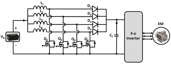
- Moreover, the four-phase interleaved boost DC–DC converter has been chosen for EVs for its several compatible reasons, such as a reduction in inductor size and output capacitor size, a more significant reduction in input current and output voltage ripples, and higher overall system efficiency
- Nevertheless, the IBC is sensitive to any changes in the duty cycle, high cost, and impact on the magnetic core due to any changes in load
- The interleaved multi-phase boost converter has an enormous controlling process, but to make the system stable for significant disturbancessome advanced control methods such as model predictive control, fuzzy controller, sliding mode control (SMC) and PI hybrid controller , high order sliding mode control (HOSMC) , active disturbance rejection control (ADRC) were proposed, designed, analyzed and applied to the multi-phase IBC. Moreover, an advanced hybrid Super-Twisting (ST) ADRC dual-loop controller was proposed and developed in , where they discussed that the ST-ADRC controller provides stronger robustness against the input voltage and load disturbances, better voltage tracking performance, and a more significant reduction in both the recovery time and voltage fluctuations compared to the conventional control systems and can improve the control performance of the converter tremendously.
3.3. Boost DC–DC Converter with Resonant Circuit (BCRC)
- Conventional boost DC–DC converters are typically operated with hard switching, which increases the switching loss of converters in BEV and PHEV powertrains
- The boost DC–DC converter topologies uses a soft-switching configuration to suppress this loss
- In the soft switching technique, during the switching transition (i.e., turn ON or turn OFF), voltage or current across the switch becomes zero
- As a result, the product of the voltage and current is zero; hence power losses are zero
- Thus, the converter can achieve high switching frequency by reducing switching losses
- Due to the switching loss reduction, the heatsink size becomes lessened, which decreases the converter volume
- The soft-switching configuration for the boost DC–DC converter with the resonant circuit, which consists of two switching devices, the main switch Q1 and the auxiliary switch Q2
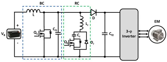
- Moreover, any abnormality in load power will not affect the converter as the converter has high safety regulations. However, BCRC is incompatible with high-power EV powertrains and does not support bidirectionality
- Soft-switching techniques are considered the best-suited way to enhance the efficiency and reliability by reducing switching losses of electric vehicles’ DC–DC converters
2.4. Full Bridge Boost DC–DC Converter (FBC)
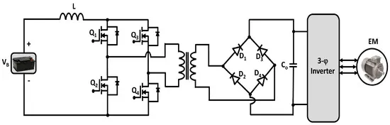
- The circuit diagram of an isolated full-bridge bidirectional DC–DC converter is depicted below
- This converter works in buck-and-boost mode, thus it is a bidirectional converter
- In the forward direction, it works as a buck converter; in the backward direction, it operates as a boost converter
- Due to this bidirectionality, an isolated full-bridge bidirectional DC–DC converter can charge the batteries and provide the voltage to the load
- The bidirectional full-bridge DC–DC converter has three working stages: DC–AC conversion as an inverter; step-up/step-down AC voltage with a high-frequency transformer (HFT); and AC–DC conversion as a rectifier
2.5. Isolated ZVS DC–DC Converter (ZVSC)
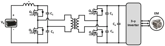
- For isolation, cold starting, and soft switching, an isolated ZVS DC–DC converter is needed an isolated zero-voltage switching DC–DC converter (ZVSC), where a dual half-bridge topology is placed on both sides of the transformer, and for soft-switching, each power switching device has a parallel capacitor
- ZVSC has a simple control technique, higher efficiency, soft-switching without extra circuity, high-power density, less component count, compact packaging, and lightweight, and no real device rating consequences compared to the traditional full-bridge DC–DC converter
2.6. Isolated Multiport DC–DC Converter (MPC)
- The isolated multiport DC–DC converter is used when more than one input source is needed with galvanic isolation between the source and load
- The multiport converter is classified into three main categories: single-input multi-output (SIMO) converter, multi-input-single-output (MISO) converter, and the multi-input-multi-output (MIMO) converter
- Among them, the MIMO multiport DC–DC converter is used in battery and plug-in hybrid vehicles
- It has coupled multiple input sources (generally supercapacitor and battery) and uses them as a single source with the advantages of various sources
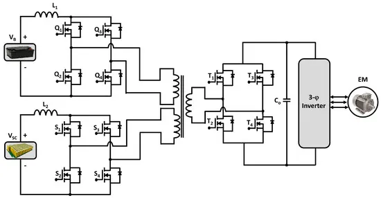
- The circuit diagram of the MIMO-MPC boost DC–DC converter which consists of a parallel connection of two boost DC–DC converters with bidirectional power flow, and it is advantageous for BEVs powertrains because it allows the converter to recharge the input sources during regenerative braking
- Because of this, the effectiveness and functionality of the MPC increase, which makes it a high-power density converter
- Moreover, all the input ports, as well as the output port, remain isolated from each other due to the interior multi-winding transformer
2.7. Multidevice Interleaved DC–DC Bidirectional Converter (MDIBC)
- A transformer is a heavy component that increases the weight of an isolated boost DC–DC converter
- For this reason, a non-isolated multidevice interleaved bidirectional DC–DC converter is used in high-power vehicular applications
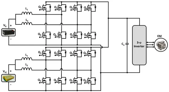
- A non-isolated multi-device interleaved bidirectional DC–DC converter (MDIBC) which uses a battery as the primary power source and a supercapacitor as a secondary or auxiliary power source
- MDIBC is a multiphase multiport bidirectional converter consisting of a phase interleaving technique with four high-frequency switching devices per phase
- The number of parallel devices per phase decreases with the increasing number of phases
- Multidevice interleaved boost DC–DC converters merge the power from two or more input sources and are supplied at a constant single output voltage level
3.Inverter(DC - AC Converter)
- The inverter is the key component for an electric vehicle because it drives the powertrain of EVs by running the electric motor with three-phase AC from the DC-link
- An inverter can be classified according to input source wise, output phase wise, output voltage wise, number of voltage levels wise, PWM wise, etc
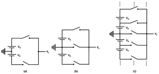
- The voltage level-wise classification of the inverter
- According to the number of voltages level-wise, an inverter can be classified into two main categories:
(a) the two-level inverter
(b) multi-level inverter
3.1. Two-Level Inverter (TLI)
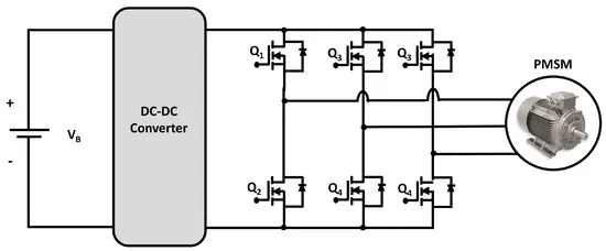
- The two-level inverter which consists of six power-switching devices
- These six power switches are connected into three legs, and each leg contains two switches, which are connected in series
- An antiparallel diode is connected to each switch to allow the current to flow in the opposite direction
- By controlling these six switches in different manners, the inverter can generate eight other states
3.2. Multi-Level Inverter (MLI)
- To gain less current and voltage total harmonic distortion (THD), less voltage stress on semiconductor devices, high efficiency, low EMI, and common-mode voltage, many conventional two-level inverters have been replaced in the past decades by their multilevel counterparts
- In addition, due to the modularity and fault tolerance capability, some MLI topologies becomes more beneficial for specific applications
- The basic concept of an MLI where switching devices carry much lower voltages than TLI, and the output filter size is decreased due to the ability to produce various voltage levels with better voltage/current quality at the lower switching frequency
- As a result, higher power levels can be achieved with MLIs without switches derating
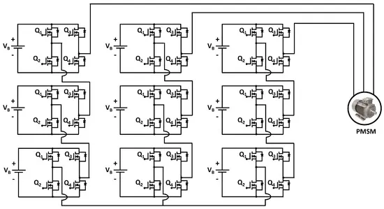
- Although multiple-DC-source multilevel inverters (MDCS-MLIs) require multiple isolated DC supplies , in high-power motor driving applications like electric vehicles, cascaded H-bridge inverter (CHB) MDCS-MLIs are most commonly utilized due to their high modularity and identical voltage rating of the employed switches
- For military combat vehicles and heavy-duty trucks, cascaded H-bridge (CHB) MLI was first recommended in 1998 as a suitable choice due to it can drive high-voltage motors easily with low-voltage switching devices
- Furthermore, there are many different topologies, such as Neutral Point Clamped (NPC) topology, Packed U-Cells (PUC) topology , and Flying Capacitor Inverter (FCI) topology , by which a multi-level inverter can be built but the topology is the cascaded multilevel inverter
- Moreover, a novel H-bridge two-transistor cascaded multi-level voltage source converter is introduced, and this promising multi-level converter could be explored for electrified transportation applications
- Below figure depicts a multi-level inverter, which consists of series-connected H-bridges
- These H-bridges can be controlled independently, and each H-bridges consists of an individual energy storage VDCML and four power-switching devices
- The MLI can create different outputs like VDCML, −VDCML, 0, and open circuits by controlling these power switches in different manners
- Conductive charging rectifiers, powertrain DC–DC converters, motor-driving inverters, and control schemes designed for EV applications based on several publications
- To develop more efficient and environmentally friendly EVs, power converters such as AC–DC, DC–DC, and DC–AC are the critical applications of modern power electronics
- After this extensive review, it can be seen that the charging section onboard PSFBC and offboard rectifiers present great performance, and the powertrain high-power DC–DC converter section and the multi-device interleaved DC–DC boost converter seem to be excellent candidates for EV applications
- On the other hand, for the powertrain DC–AC inverter, the third harmonic injected seven-level MLI can be considered a well-suited candidate for the powertrain of electric vehicles
2. An Electric Vehicle's powertrain with 72V battery pack in shown in the diagram below. The duty ratio for acceleration operation is 'd1' and for the braking operation the duty ratio is 'd2'.
Given Parameters:
Motor and Controller Parameters:
Rated Armature voltage(Vs) = 72 V
Rated armature current (Ia)= 400 A
Ra= 0.5Ω, KΦ= 0.7 Volt second
Chopper Switching frequency= 400 Hz
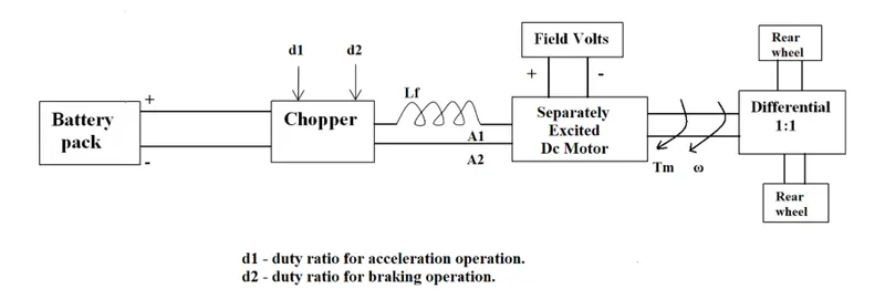
consider seperately excited dc motor as shown below,
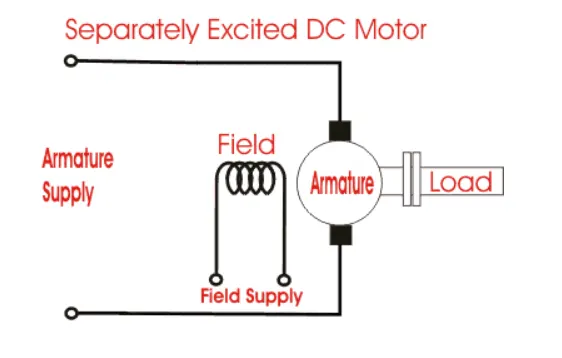
Supply voltage(Vs) =72 volts
Duty ratio (d) =0.7
Thus motor voltage that come across the motor= Va=Vs*d=72*0.7= 50.4 volts
The torque speed relationship is governed by equation
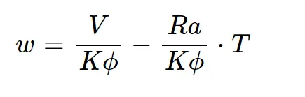
where T= motor torque
V=Va= motor voltage
Ra= armature resistance
w= angular speed of motor in rad/sec
Thus
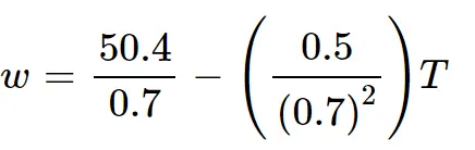
Thus we get

now ,The vehicle speed-torque characteristics are given by the below equation

equating above two equation , we get


The solution for the quadratic equation

is given by
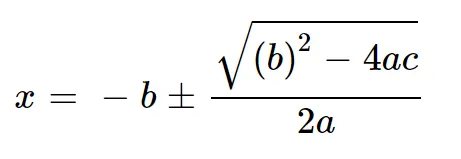
Thus we get w=38.95 rad/sec and w=-231.08 rad /sec
EV steady state speed is 38.95 rad/sec
To Develop a mathematical model of a DC Motor for the below equation using Simulink.
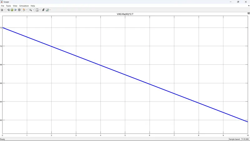
ω= V/Kϕ -Ra/Kϕ^2 .T
let us draw a model for the above quation as shown below.
let V=50.4 volts
ko=0.7
Ra=0.5 ohms
and let us consider torque as linearly increasing signal, let T be a ramp signal.

the scope of speed of motor is shown below
thus we find that , for the fixed voltage, the speed of the motor is inversely propotional to load
this means that increase in load torque will result in decrease in speed.
4.Induction Versus DC brushless motors by Wally Rippel, Tesla
Induction motor
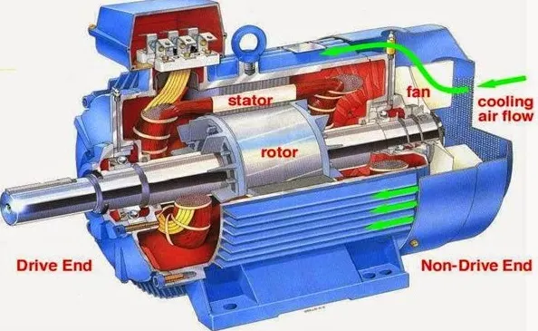
An induction motor or asynchronous motor is an AC electric motor in which the electric current in the rotor needed to produce torque is obtained by electromagnetic induction from the magnetic field of the stator winding. An induction motor can therefore be made without electrical connections to the rotor.
Brushless DC motor
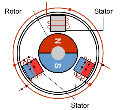
A brushless DC electric motor, also known as an electronically commutated motor or synchronous DC motor, is a synchronous motor using a direct current electric power supply.
One Size Does Not Fit All
In that odious world of gas powered vehicles, engines are not all alike. There are flat-heads, Hemis, straight, opposed, and V configurations. And on and on. One would have thought that, years ago, someone would have figured out which was best. That would have ended all the choices and thereafter only the one best engine type would be in production. Not so. There is no one best engine type, rather there are different types of engines to suit personal requirements, such as price and performance. This is also true for electric vehicle drives.
Brushless DC motor vs Induction motor by Wally Ripple
- With brushless machines, the rotor includes two or more permanent magnets that generate a DC magnetic field (as seen from the vantage point of the rotor). In turn, this magnetic field enters the stator core (a core made up of thin, stacked laminations) and interacts with currents flowing within the windings to produce a torque interaction between the rotor and stator. As the rotor rotates, it is necessary that the magnitude and polarity of the stator currents be continuously varied – and in just the right way - such that the torque remains constant and the conversion of electrical to mechanical energy is optimally efficient. The device that provides this current control is called an inverter Without it, brushless motors are useless motors.
- Unlike the DC brushless rotor, the induction rotor has no magnets – just stacked steel laminations with buried peripheral conductors that form a “shorted structure.” Currents flowing in the stator windings produce a rotating magnetic field that enters the rotor. In turn, the frequency of this magnetic field as “seen” by the rotor is equal to the difference between the applied electrical frequency and the rotational “frequency” of the rotor itself. Accordingly, an induced voltage exists across the shorted structure that is proportionate to this speed difference between the rotor and electrical frequency. In response to this voltage, currents are produced within the rotor conductors that are approximately proportionate to the voltage, hence the speed difference. Finally, these currents interact with the original magnetic field to produce forces – a component of which is the desired rotor torque.
- When a 3-phase induction motor is connected to utility type 3-phase power, torque is produced at the outset; the motor has the ability to start under load. No inverter is needed. (Were an inverter needed, Tesla’s invention would have been useless until sometime in the 1960s.) The fact that induction motors are directly compatible with conventional utility power is the main reason for their success. In contrast, a brushless DC motor produces no starting torque when directly connected to fixed frequency utility power. They really need the aid of an inverter whose “phase” is maintained in step with the angular position of the rotor.
- While 3-phase induction motors have great utility, they also have some severe limitations. They cannot operate from DC; AC is a must. Shaft speed is proportionate to line frequency. Hence, when used with utility power, they are constant speed machines. Finally, when operated from utility power, they have limited starting torque and somewhat limited running peak torque capabilities, when compared to DC type machines.
- Add an inverter (without any feedback control) and it becomes possible to power an induction machine from a battery or other DC source; variable speed also becomes possible simply by adjusting the inverter frequency. Still, torque performance is low compared with DC machines. Add some feedback loops such that the inverter produces the exact frequency that the motor “desires,” and the induction motor is now capable of competing with DC and DC brushless for vehicle applications.
-
Both DC brushless and induction drives use motors having similar stators. Both drives use 3-phase modulating inverters. The only differences are the rotors and the inverter controls. And with digital controllers, the only control differences are with control code. One of the main differences is that much less rotor heat is generated with the DC brushless drive. Rotor cooling is easier and peak point efficiency is generally higher for this drive. The DC brushless drive can also operate at unity power factor, whereas the best power factor for the induction drive is about 85 percent. This means that the peak point energy efficiency for a DC brushless drive will typically be a few percentage points higher than for an induction drive.
- Induction machine when operated with a smart inverter has an advantage over a DC brushless machine – magnetic and conduction losses can be traded such that efficiency is optimized. This advantage becomes increasingly important as performance is increased. With DC brushless, as machine size grows, the magnetic losses increase proportionately and part load efficiency drops. With induction, as machine size grows, losses do not necessarily grow. Thus, induction drives may be the favored approach where high-performance is desired; peak efficiency will be a little less than with DC brushless, but average efficiency may actually be better.
- Permanent magnets are expensive – something like $50 per kilogram. Permanent magnet (PM) rotors are also difficult to handle due to very large forces that come into play when anything ferromagnetic materials gets close to them. This means that induction motors will likely retain a cost advantage over PM machines. Also, due to the field weakening capabilities of induction machines, inverter ratings and costs appear to be lower, especially for high performance drives. Since spinning induction machines produce little or no voltage when de-excited, they are easier to protect. Induction machines are more difficult to control. The control laws are more complex and difficult to understand. Achieving stability over the entire torque-speed range and over temperature is more difficult with induction than with DC brushless. This means added development costs, but likely little or no recurring costs.
Author conclusion : DC brushless drives will likely continue to dominate in the hybrid and coming plug-in hybrid markets, and that induction drives will likely maintain dominance for the high-performance pure electrics. The question is what will happen as hybrids become more electrically intensive and as their performance levels increase? The fact that so much of the hardware is common for both drives could mean that we will see induction and DC brushless live and work side by side during the coming golden era of hybrid and electric vehicles.