Week-6 Challenge: EV Drivetrain
Week-6 Challenge: EV Drivetrain
1) Which types of power converter circuits are employed in electric and hybrid electric vehicle?
Power converters are electrical and electronic circuits that are used to either connect DC to AC and vice versa or to convert one level of DC voltage into another one i.e step up or step down according to requirement.
With the focus on vehicular technology shifting towards replacing mechanical, hydraulic, or pneumatic systems with electrical systems, power electronic circuits (PECs) have gained a lot of importance in the last decade. Increasing vehicular loads such as utility, entertainment, luxury, and safety loads have increased the demand for compact and efficient PECs. The electric components inside the vehicle vary in their voltage requirements, with a majority of them running on lower voltages. This includes the radio, dashboard readouts, air conditioning, and in-built computers and displays.
Commercial electric vehicles may be broadly classified as:
- Battery electric vehicles (BEVs),
- Hybrid electric vehicles (HEVs) and
- Fuel cell vehicles (FCVs).
BEVs are purely electric vehicles (EVs), whereas HEVs combine EVs and internal combustion engines (ICEs). FCVs use power from both the battery and fuel cell stack.
The different configurations of EV power supply show that at least one DC/DC converter is necessary to interface the FC, the battery, or the supercapacitors module to the DC-link.
The main components of an Electric Vehicle are a DC-AC inverter, a DC-DC converter, a battery, and an electric motor.
There are two major power electronic units in the general configuration
- DC-DC converter
- DC-AC inverter
Usually, AC motors are used in HEVs or EVs for traction and they are fed by an inverter and it is fed by a DC-DC converter.
Introduction to Power Electronic Converters –
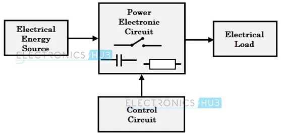
Power electronic converters uses power electronic components such as SCRs, TRIACs, IGBTs to control and convert electric power 7 the main aim of the converter is to produce power conditioning with respect to the certain application.
According to the respective functions performed, power electronic converters are categorized in the following types –
AC to DC – Rectifier, it converts AC to unipolar (DC) Current.
DC to AC – Inverter, it converts DC to AC of desired frequency and voltage.
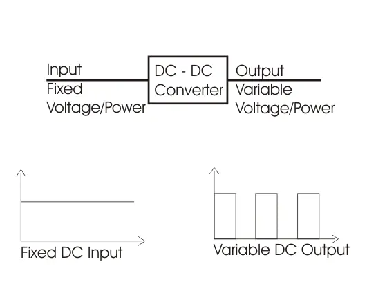
DC to DC – Chopper, it converts constant to variable DC or variable DC to constant DC.
AC to AC – Cycloconverter, Matrix converter – it converts AC of desired frequency or desired voltage magnitude from AC supply.
These power electronic converters may be found in wide variety of applications such as switch mode power supplies (SMPS), Electric Machine control, Energy storage systems, Lightning drives, Power generation & distribution, Active power filters, Renewable energy conversion, flexible energy transmission let us go in detail about each converter
AC to DC converters (Rectifiers) –
These converts AC supply from main lines to DC supply or the load. The block diagram of this converter is shown as below –
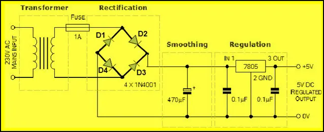
The essential components of the rectifier include Transformer, Control Block, Filter, Switching Unit.
Transformer adjusts the primary AC source supply to the input of rectifier stage. Usually it is step down transformer that reduces the supply voltage to a circuit operating range.
The rectifier converts the low voltage AC supply into DC supply. It consists of diode / thyristors based on type of rectifier, the output of the rectifier is of pulsed DC and hence it is filtered using filter circuit, which is usually made with a capacitor or a choke.
The control block controls the firing angle of thyristors in case of phased controlled rectifiers. Since the diode is not controllable device, control block is not needed in case of diode rectifiers.
Rectifiers are divided into two types -
- Uncontrolled diode rectifiers.
- Controlled rectifiers.
DC to AC converters (Inverter)-
These converters are connected between DC source of fixed input and variable AC load. Most commonly these DC to AC converters are called Inverters. An inverter is a static device that converts fixed DC supply voltage to variable AC supply voltage.
Fixed DC voltage is obtained from batteries or by DC link in most power electronic converters. The output of the inverter can be variable or fixed AC voltage with variable or fixed frequency.
This conversion from DC to AC along with variable supply is produced varying the triggering angle of the thyristors. Most of the thyristors are used in inverters are employed with forced commutation technique.
This can be single phase or three phase inverter depending upon the supply voltage. These converters are mainly divided into two groups - one is PWM based inverters and other is multilevel inverters.
Further these are classified voltage source inverters and current source inverter. Each type is subdivided into different types of PWM, SVPWM etc. Multilevel inverters are most popular in industrial applications.
DC to DC converters –
The working principle of the DC-to-DC converter is very simple. The inductor in the input resistance has an unexpected variation in the input current. If the switch is kept as high (on), then the inductor feeds the energy from the input and stores the energy in the form of magnetic energy.
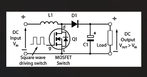
If the switch is kept as low (off), it discharges the energy. Here, the output of the capacitor is assumed as high that is sufficient for the time constant of an RC circuit on the output side. The huge time constant is compared with the switching period and made sure that the steady-state is a constant output voltage. It should be Vo(t) = Vo(constant) and present at the load terminal.
Many DC operated applications need different levels of DC voltage from a fixed DC source.
Some of these applications include subway cars, DC traction systems, control of large DC motors, battery operated vehicles, large buses, etc. which require variable DC to produce variable speed, so a power conversion device is needed.
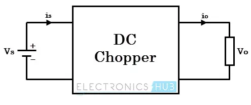
A DC chopper is a static device that converts a fixed input DC voltage to variable DC output of different magnitude (which can be lower or higher) than input value.
The chopper circuit is connected between DC input source and DC load. The chopper consists of power electronics switching devices such as pulse with modulation (PWM) control.
DC choppers are mainly used in DC drives i.e. EVs and HEVs.
DC choppers are classified into three basic types based on input and output voltage levels and are discussed below –
Step Up Chopper or Boost Up Converter –
In this chopper the output voltage is always greater than input voltage and a switch is also used connected in parallel with the load and the switch is thyristor or a SCR.
A diode is placed in series with the load that allows load current to flow when the thyristor is turned OFF.
When thyristor is turned ON, the diode is reverse biased and hence it isolates the load circuit from the source. So the inductor charges to the maximum input voltage source.
When the thyristor is turned OFF, the load gets the voltage from the input as well as from inductor. So the voltage appearing across the converter output will be more than the input.
Step Down Chopper or Buck Converter –
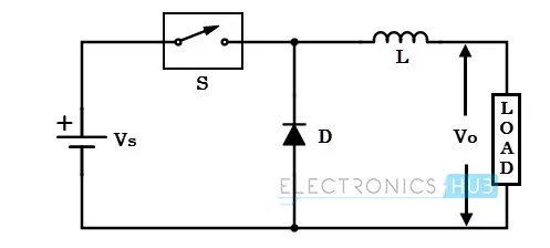
a step down chopper produces an average output voltage lower than input DC voltage. Here the switching component is a thyristor that switches the input voltage to the load when it is triggers at particular instant.
A diode acts as a freewheeling diode that allows the load current flow through it when thyristor is turned OFF. If this diode is absent, a high induced EMF in inductance may cause damage to the switching device.
The average output voltage of the converter is varied by controlling turn ON/OFF periods of thyristor. When thyristor is turned ON, the output voltage is same as the input voltage and if it is turned OFF, the output voltage is zero. And the output voltage is equal to (TON / T) Vin. So by controlling the duty ratio K = (TON /T), The output voltage will be increased.
Flyback Converter –
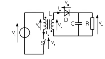
The flyback converter is used in both AC/DC & DC/DC conversion with galvanic isolation between the input and any outputs. The flyback converter is a buck – boost converter with the inductor split to form a transformer, so that the voltage ratios are multiplied with an additional advantage of isolation for example a Driving lamp or a Voltage Multiplier the rectifying diode of the boost converter is left out and the device is called a flyback transformer.
Forward Converter –
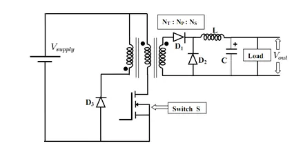
The forward converter is a DC – DC converter uses transformer to increase or decrease the output voltage and provide galvanic isolation for the load with multiple output windings and it is possible to provide low voltages and high voltages outputs simultaneously
While it looks similar as flyback converter, it operates in a fundamentally different way and is generally more energy efficient. A flyback converter stores the energy in the magnetic field in the inductor gap during the time the converter is switching the element (transistor) is conducting. When the switch turns OFF, the stored magnetic field collapses and energy is transferred to the output of the flyback converter as electric current. The flyback converter can be viewed as two inductors sharing a common core with opposite polarity windings.
In contrast the forward converter (which is based on a transformer with same polarity windings, higher magnetizing inductance and no air gap) doesn’t store the energy during the conduction time of switching element - transformers cannot store a significant amount of energy, unlike inductors instead energy is passed directly to the output of the forward converter by transformer action during switch conductance phase.
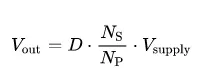
While the output of the flyback converter is theoretically infinite, the maximum output voltage of the forward converter is constrained by the transformer turns ratio Ns / Np.
AC – AC converter –
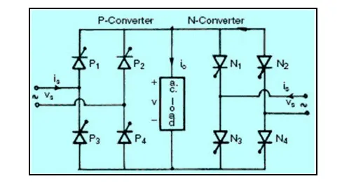
These types of power electronic converters are used to convert alternating current waveforms of specific magnitude and specific frequency into alternating current waveforms with different magnitude and different frequency, as the signal remains AC and hence this converter is termed as AC –AC converter. To operate a few devices and machines we require some specific voltage with specific frequency can be obtained with AC – AC converters and by regulating AC power using AC – AC converter we can regulate the speed of induction motors. There are different types of AC –AC converters which are classified based on different criteria.
Q.2) An electric vehicle drivetrain with 72 V battery pack is shown in the diagram below. The duty ratio for acceleration operation is “D1” and for the braking operation the duty ratio is “D2”, What is EV steady state speed if duty cycle is 70%?
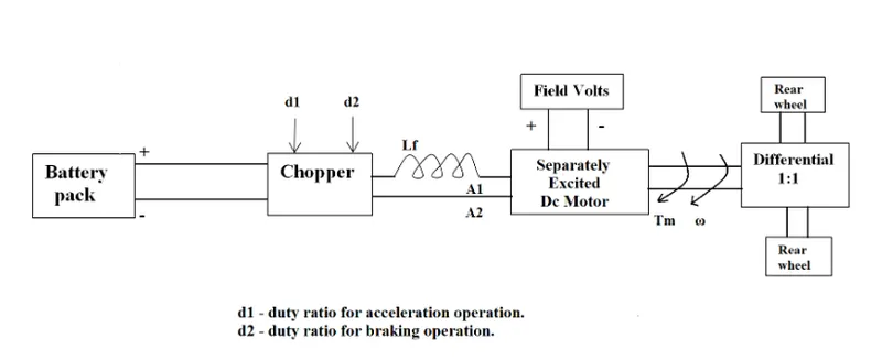
The other parameters of the electric vehicle is given below,
Motor and Controller Parameters:
Rated Armature voltage= 72 V
Rated armature current= 400 A
Ra= 0.5Ω, KΦ= 0.7 Volt second
Chopper Switching frequency= 400 Hz
The vehicle speed-torque characteristics are given by the below equation

What is EV steady state speed if duty cycle is 70%?
given –
Rated Armature Voltage = 72 V.
Rated Armature current = 400 A.
Ra = 0.5 Ω">ΩΩ.
Kϕ">ϕ = 0.7 V–s.
Chopper switching frequency = 400Hz.
The vehicle characteristics are given by equation –
Tm = 24.7 + 0.0051 ω">ω2. ……… (1)
it is given that the duty cycle is 70% so the average voltage is Vo = [72*(700 / 100)] = 50.40 V.
we know the DC motor torque speed equation is given by: -
Tm = [Vo * Kϕ">ϕ – {W * (Kϕ">ϕ)2 / Ra}]………….(2)
Putting all the values in equation 2 we get,
Tm = [(50.40 * 0.7 / 0.5] – {ω">ω * 0.72 / 0.5}]
Tm = 70.56 – 0.98 ω">ω …………. (3)
Now we have two equations, equating equations (2) & (3) we get,
Tm = 24.7 + 0.0051ω">ω2 = 70.56 – 0.98W
0.0051 ω">ω2 + 0.98 W – 45.86 = 0
using formula
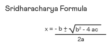
where a= 0.0051 b= 0.98 c= -45.86
Therefore putting this values in above equation,
Solving this equation we get two different values of omega that is
ω">ω = 38.91 Rad / Sec.
ω">ω = -231.07 Rad / Sec.
Speed cannot be in negative, therefore speed ω">ω = 38.91 Rad/sec
Omega with positive sign is for the forward direction so we will take only ω">ω = 38.92 Rad / Sec. for steady state speed.
Q.3) Develop a mathematical model of a DC Motor for the below equation using Simulink.
ω">ω= V/Kϕ">ϕ -Ra/Kϕ">ϕ^2 .T
Here this model is created from torque speed equation using simulink.
Fig- Mathematical Model
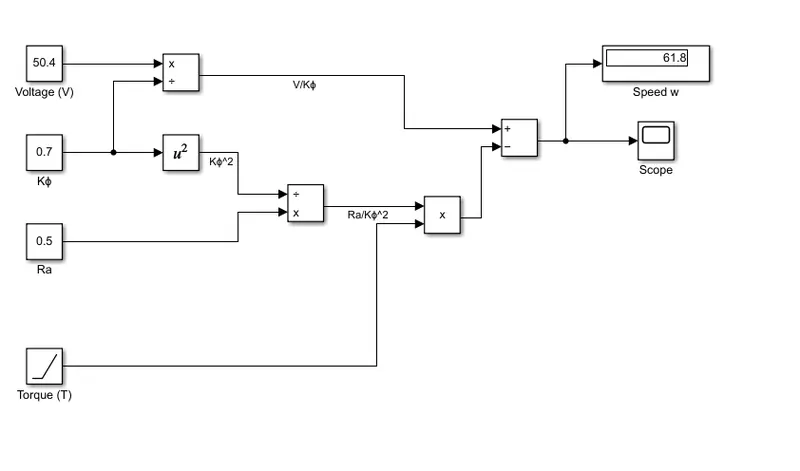
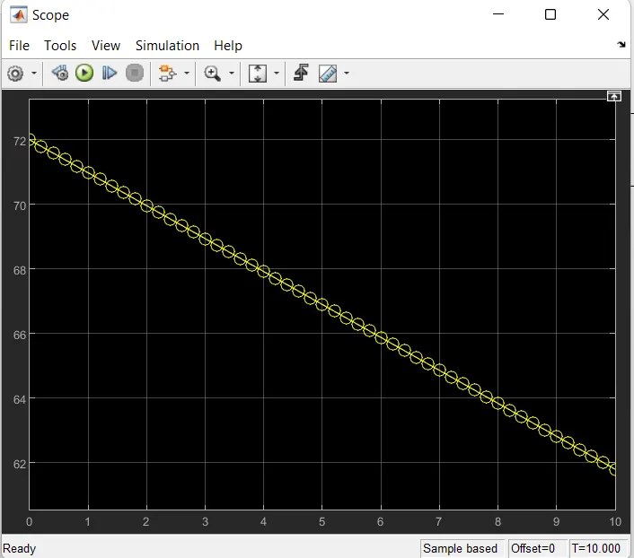
Here we have verified this equation by giving the values of torque,Voltage,Ra,Kϕ.
Q.4) Study the blog on Induction vs. DC brushless motors by Wally Ripple, Tesla & explain in brief about the author’s perspective.
Wally Ripple is a long-time proponent of electric vehicles. Prior to joining Tesla Motors, he was an engineer at Aeroviornment, where he helped to develop the Ev1 for GENERAL MOTORS.
He was featured in the documentary movie – Who killed the Electric Car? Wally has also worked for the Jet Propulsion Laboratory on electric vehicle battery research, among other projects.
In 1968 as a Caltech Undergraduate student, he built an electric car (A converted 1958 Volkswagen Microbus) and won the great Transcontinental electric car race against MIT.
He has written a blog on Induction Motor Vs. DC Brushless Motors by comparing all its strengths and weaknesses.
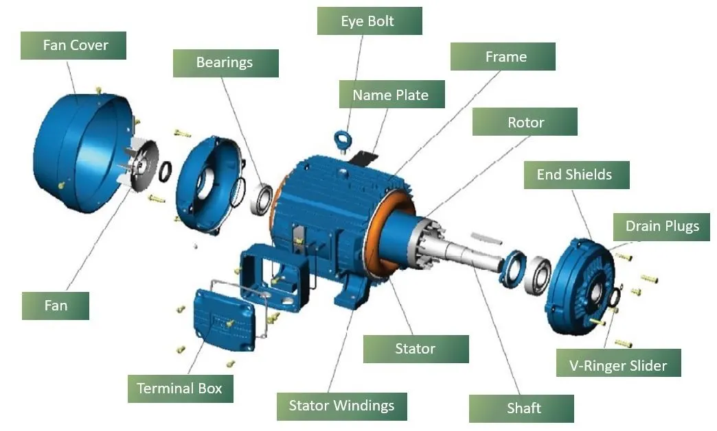
Fig- AC Induction motor
A forerunner of the 3Ph Induction motor motor was invented by Nikola Tesla sometime before 1889. Curiously, the stators for the 3-phase induction motor and the DC brushless motor are virtually identical. Both have three sets of “distributed windings” that are inserted within the stator core. The essential difference between the two machines is with the rotor.
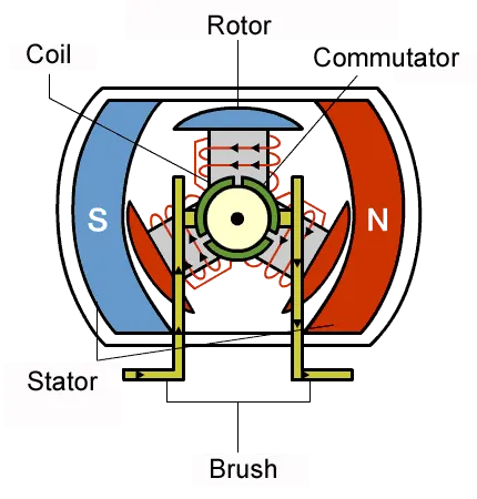
Fig- Brushless Dc motor
In brushless machines, the rotor has 2 or more permanent Magnets which will generate a DC magnetic field and in turn, this magnetic field enters the stator core and interacts with currents flowing within windings to produce torque interaction between the rotor and stator.
Both DC brushless and induction drives use motors having similar stators. Both drives use 3-phase modulating inverters. The only differences are the rotors and the inverter controls. And with digital controllers, the only control differences are with control code. (DC brushless drives require an absolute position sensor, while induction drives require only a speed sensor; these differences are relatively small.)
One of the main differences is that much less rotor heat is generated with the DC brushless drive. Rotor cooling is easier and peak point efficiency is generally higher for this drive. The DC brushless drive can also operate at unity power factor, whereas the best power factor for the induction drive is about 85 percent. This means that the peak point energy efficiency for a DC brushless drive will typically be a few percentage points higher than for an induction drive.
In an ideal brushless drive, the strength of the magnetic field produced by the permanent magnets would be adjustable. When maximum torque is required, especially at low speeds, the magnetic field strength (B) should be maximum – so that inverter and motor currents are maintained at their lowest possible values. This minimizes the I² R (current² resistance) losses and thereby optimizes efficiency. Likewise, when torque levels are low, the B field should be reduced such that eddy and hysterisis losses due to B are also reduced. Ideally, B should be adjusted such that the sum of the eddy, hysteresis, and I² losses is minimized. Unfortunately, there is no easy way of changing B with permanent magnets.
In contrast, induction machines have no magnets and B fields are “adjustable,” since B is proportionate to V/f (voltage to frequency). This means that at light loads the inverter can reduce voltage such that magnetic losses are reduced and efficiency is maximized. Thus, the induction machine when operated with a smart inverter has an advantage over a DC brushless machine – magnetic and conduction losses can be traded such that efficiency is optimized. This advantage becomes increasingly important as performance is increased. With DC brushless, as machine size grows, the magnetic losses increase proportionately and part load efficiency drops. With induction, as machine size grows, losses do not necessarily grow. Thus, induction drives may be the favored approach where high-performance is desired; peak efficiency will be a little less than with DC brushless, but average efficiency may actually be better.
Permanent magnets are expensive – something like $50 per kilogram. Permanent magnet (PM) rotors are also difficult to handle due to very large forces that come into play when anything ferromagnetic gets close to them. This means that induction motors will likely retain a cost advantage over PM machines. Also, due to the field weakening capabilities of induction machines, inverter ratings and costs appear to be lower, especially for high performance drives. Since spinning induction machines produce little or no voltage when de-excited, they are easier to protect.
I almost forgot: Induction machines are more difficult to control. The control laws are more complex and difficult to understand. Achieving stability over the entire torque-speed range and over temperature is more difficult with induction than with DC brushless. This means added development costs, but likely little or no recurring costs.
The author’s perspective is that the DC brushless drives will likely continue to dominate in the hybrid and coming plug-in hybrid markets, and that induction drives will likely maintain dominance for the high-performance pure electrics. The question is what will happen as hybrids become more electrically intensive and as their performance levels increase? The fact that so much of the hardware is common for both drives could mean that we will see induction and DC brushless live and work side by side during the coming golden era of hybrid and electric vehicles.