Week-6 Challenge: EV Drivetrain
1. Which types of power converter circuits are employed in electric and hybrid electric vehicles?
Power Converters in EV and HEV can be categorized into these following:
For,
- EV charger: AC-DC converter
- EV /HEV Motor Drive: DC-AC Converter
- Auxiliaries: DC-DC, in HEV (AC-AC also used.)
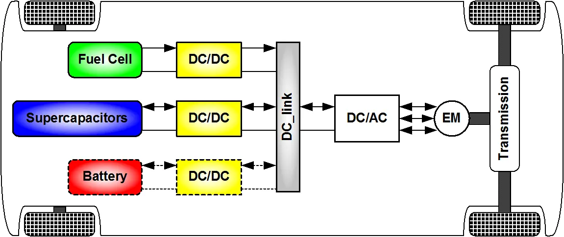
The main components of an Electric Vehicle are DC-AC inverter, DC-DC converter, battery, and electric motor.
There are two major power electronic units in the general configuration
- AC-DC converter
- DC-DC converter
- DC-AC inverter
AC-DC Converter
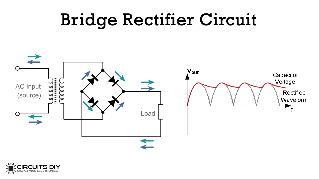
While charging the EV we need AC-DC converter as Battery runs on DC voltage. But We know AC Voltage is used broadly all over the World and easy to get 240V AC. So, we take the input AC voltage and convert it into DC and then fed to Battery and thus Battery gets charged.
A rectifier is used to convert AC to DC.
DC-AC Converter
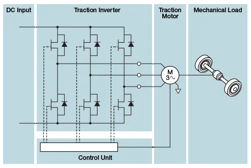
An inverter is a device that converts DC power from the battery to AC power used in an Electric vehicle motor. The inverter can change the speed at which the motor rotates by adjusting the frequency of the alternating current.
Overview of DC-DC converter
DC-DC converters in an electric vehicle may be classified into unidirectional and bidirectional converters. Unidirectional DC-DC converters cater to various onboard loads such as sensors, controls, entertainment, utility, and safety equipment. They are also used in DC motor drives and electric traction. Bidirectional DC-DC converters find applications in places where battery charging, regenerative braking, and backup power are required. The power flow in a bidirectional converter is usually from a low voltage end such as a battery or a supercapacitor to a high voltage side and is referred to as boost operation.
During Regenerative braking, the power flows back to the low voltage bus to recharge the battery (buck mode). As a backup power system, the bidirectional DC-DC converter facilitates the safe operation of the vehicle when ICEs or electric drives fail to drive the motor. Due to the aforementioned reasons, high power bidirectional DC-DC converters have gained a lot of importance in the recent past.
Why is a DC/DC converter necessary?
While DC/DC converters can be based on a number of different designs, the underlying function remains the same. We might be talking about a step-up converter, which turns a low-voltage input into a high-voltage output, or a step-down converter, which does the opposite.
In electric vehicles which use a DC motor, running the motor can use up to three times the voltage provided by the battery. With the help of the right converter, we can bridge this gap without having to possibility to a larger, prohibitively heavy battery.
Chopper used as DC to DC converter.
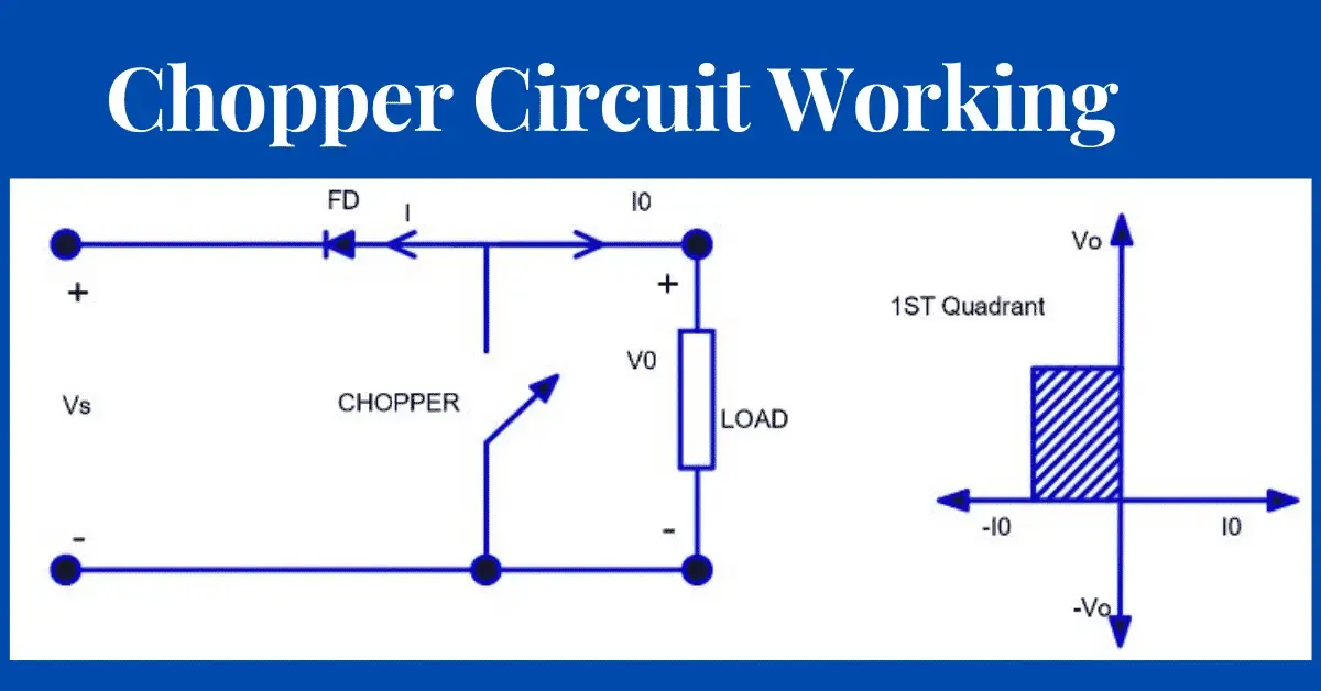
Image Source: Google images
--------------------------------------------------------------------------------------------------------------------------------------------------------
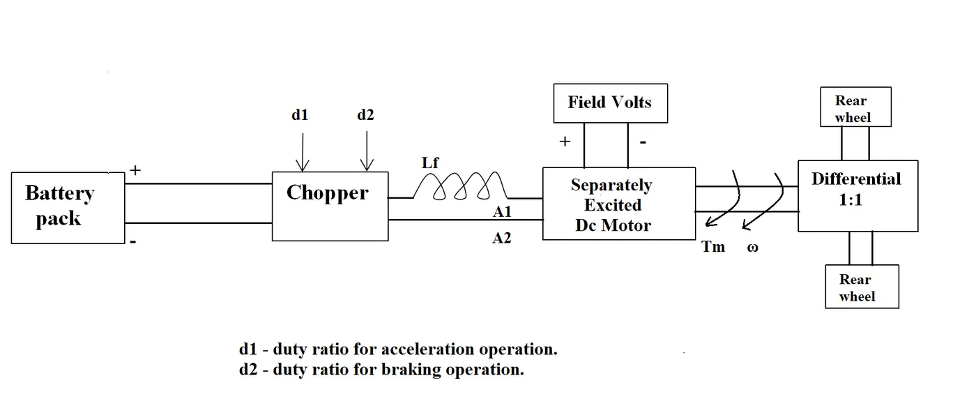
2. An Electric Vehicle's powertrain with 72V battery pack in shown in the diagram below. The duty ratio for acceleration operation is 'd1' and for the braking operation the duty ratio is 'd2'.
The other parameters of the electric vehicle is given below,
Motor and Controller Parameters:
Rated Armature voltage= 72 V
Rated armature current= 400 A
Ra= 0.5Ω, KΦ= 0.7 Volt second
Chopper Switching frequency= 400 Hz
The vehicle speed-torque characteristics are given by the below equation

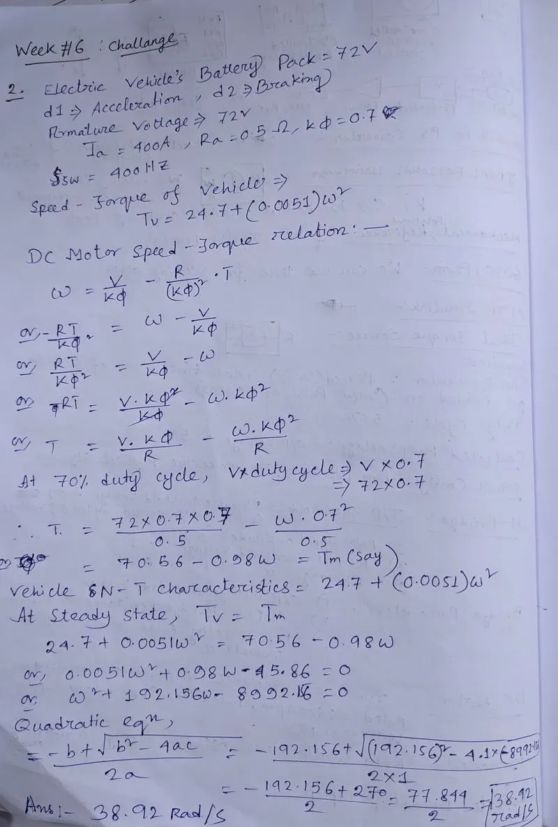
What is EV steady state speed if duty cycle is 70%?
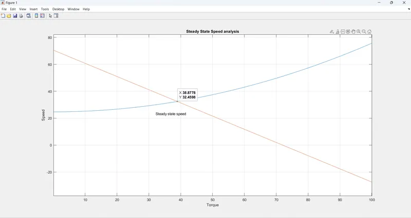
We can check in MATLAB also:
3. Develop a mathematical model of a DC Motor for the equation below using Simulink.
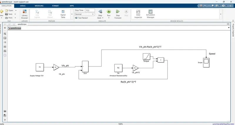
- Used Constant block to assign 72 V DC Voltage and Armature Resistance.
- Gain blocks used for assigning 1/kϕ and1/(kϕ)^2
- Sum Block for summing function
- As we are going to plot the Torque -Speed value, The Toque must be Time Variable Value. To assigning Time-Variable used Ramp function as we know Ramp function value changes with time.
- Scope for Visualization of the Result
Parameters Value:
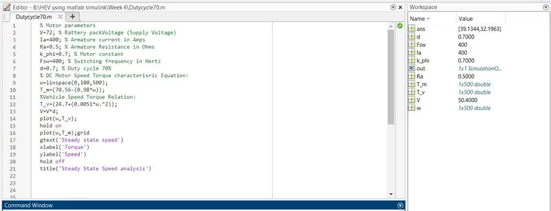
We used same values of parameters of the previous example.
Model:
Result:
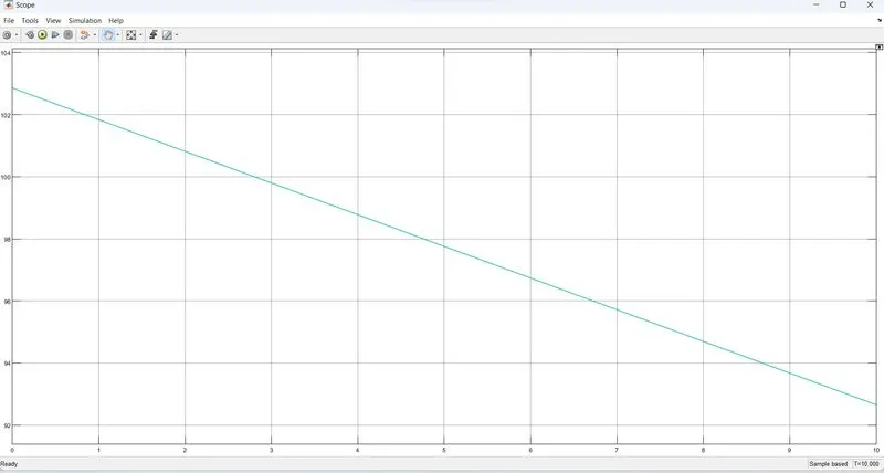
As we can see the Max speed of almost 100 (In MATLAB w(500)) rpm and with increment of the Torque Value. The graph is perfectly following the Speed -Torque characteristic of DC Shunt Motor.
------------------------------------------------------------------------------------------------------------------------------------
4. Refer to the blog on below topic:
Induction Versus DC brushless motors by Wally Rippel, Tesla
Explain in brief about author’s perspective.
In this Blog Author Mr. Wally Rippel, telling us about the brief of construction of DC Brushless Motor and Induction Motor and Their Difference.
Construction:
BLDC:
With brushless machines, the rotor includes two or more permanent magnets that generate a DC magnetic field (as seen from the vantage point of the rotor). In turn, this magnetic field enters the stator core (a core made up of thin, stacked laminations) and interacts with currents flowing within the windings to produce a torque interaction between the rotor and stator. As the rotor rotates, it is necessary that the magnitude and polarity of the stator currents be continuously varied – and in just the right way - such that the torque remains constant and the conversion of electrical to mechanical energy is optimally efficient. The device that provides this current control is called an inverter. Without it, brushless motors are useless motors.
Induction:
Unlike the DC brushless rotor, the induction rotor has no magnets – just stacked steel laminations with buried peripheral conductors that form a “shorted structure.” Currents flowing in the stator windings produce a rotating magnetic field that enters the rotor. In turn, the frequency of this magnetic field as “seen” by the rotor is equal to the difference between the applied electrical frequency and the rotational “frequency” of the rotor itself. Accordingly, an induced voltage exists across the shorted structure that is proportionate to this speed difference between the rotor and electrical frequency. In response to this voltage, currents are produced within the rotor conductors that are approximately proportionate to the voltage, hence the speed difference. Finally, these currents interact with the original magnetic field to produce forces – a component of which is the desired rotor torque.
Difference:
- One of the main differences is that much less rotor heat is generated with the DC brushless drive. Rotor cooling is easier and peak point efficiency is generally higher for this drive. The DC brushless drive can also operate at unity power factor, whereas the best power factor for the induction drive is about 85 percent. This means that the peak point energy efficiency for a DC brushless drive will typically be a few percentage points higher than for an induction drive.
- In an ideal brushless drive, the strength of the magnetic field produced by the permanent magnets would be adjustable. When maximum torque is required, especially at low speeds, the magnetic field strength (B) should be maximum – so that inverter and motor currents are maintained at their lowest possible values. This minimizes the I² R (current² resistance) losses and thereby optimizes efficiency. Likewise, when torque levels are low, the B field should be reduced such that eddy and hysteresis losses due to B are also reduced. Ideally, B should be adjusted such that the sum of the eddy, hysteresis, and I² losses is minimized. Unfortunately, there is no easy way of changing B with permanent magnets.
- In contrast, induction machines have no magnets and B fields are “adjustable,” since B is proportionate to V/f (voltage to frequency). This means that at light loads the inverter can reduce voltage such that magnetic losses are reduced and efficiency is maximized. Thus, the induction machine when operated with a smart inverter has an advantage over a DC brushless machine – magnetic and conduction losses can be traded such that efficiency is optimized. This advantage becomes increasingly important as performance is increased. With DC brushless, as machine size grows, the magnetic losses increase proportionately and part load efficiency drops. With induction, as machine size grows, losses do not necessarily grow. Thus, induction drives may be the favored approach where high-performance is desired; peak efficiency will be a little less than with DC brushless, but average efficiency may actually be better.
- Permanent magnets are expensive – something like $50 per kilogram. Permanent magnet (PM) rotors are also difficult to handle due to very large forces that come into play when anything ferromagnetic gets close to them. This means that induction motors will likely retain a cost advantage over PM machines. Also, due to the field weakening capabilities of induction machines, inverter ratings and costs appear to be lower, especially for high performance drives. Since spinning induction machines produce little or no voltage when de-excited, they are easier to protect.
- Induction machines are more difficult to control. The control laws are more complex and difficult to understand. Achieving stability over the entire torque-speed range and over temperature is more difficult with induction than with DC brushless. This means added development costs, but likely little or no recurring costs.
Conclusion:
DC brushless drives will likely continue to dominate in the hybrid and coming plug-in hybrid markets, and that induction drives will likely maintain dominance for the high-performance pure electrics. The question is what will happen as hybrids become more electrically intensive and as their performance levels increase? The fact that so much of the hardware is common for both drives could mean that we will see induction and DC brushless live and work side by side during the coming golden era of hybrid and electric vehicles.
Both the motors have their own advantages with different applications.