Project - Speed Control of a Direct Current (DC) motor:
Objective: First we will discuss a brief of DC Motor and then we'll build a Simulink Model of given DC Motor schematic Diagram and check the Speed control of the Motor with given Input.
What is DC Motor?
A machine that converts DC power into Mechanical Power is known as DC motor.
Working Principle:
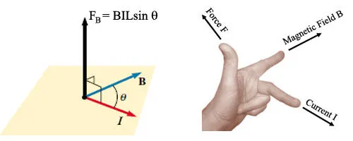
When a current carrying conductor is placed in a magnetic field, the conductor will experience a Mechanical force. The direction of the force is given by Fleming's Left-hand Rule.
Fleming's Left-hand Rule.
The electromagnetic force experienced by a current I placed in a magnetic field B.
The magnitude of this force is given by F= BIL sinθ, where L is the length of the conductor placed inside the field and θ is the angle between I and B.
The direction of the force is given by Fleming’s Left Hand Rule.
Concept of Back EMF:
When Due to torque the armature of dc motor rotates, the armature conductors move through the magnetic field and emf induced which acts opposite direction to the applied Voltage.
According to Lenz's Law the direction of induced emf is such that it opposes the cause producing it.
As Armature rotates the Back emf (Eb) is induced which opposes the supply Voltage V. V has to force current through the armature against Back emf (Eb). The Electric work done in overcoming and causing current to flow against Eb is converted into Mechanical Energy in the armature. So, energy conversion is possible in dc motor because of Back emf.
Net Voltage across armature circuit= V-Eb
Ra=Armature Resistance
Ia=Armature Current
Ia=(V-Eb)/Ra
This is a Schematic Diagram of a Dc motor. We'll build a Simulink Model of it and observe the Speed control of the Motor with the given Input.
What is DC Motor?
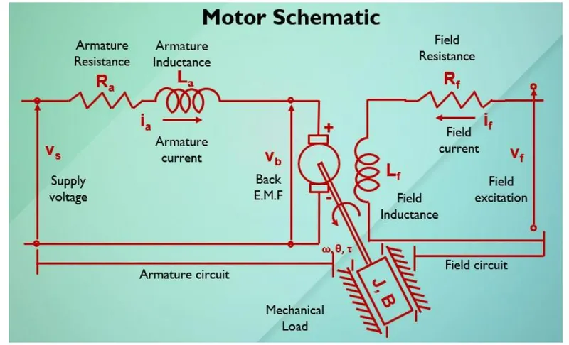
Here are the parameters of Motor:
% Motor Design Parameters
J=.01; % Moment of inertia of the rotor in Kgm^2
Bm=.1; % Motor Viscous Friction Constant in Nms
Kb=.01; %Back Emf Constant
Kt=.01; % Torque Constant in Nm/Ampere
R= 1; %Armature Resistance in Ohms
L= .5; %Armature Inductance in Henry
We know that,
Torque Constant (Kt)*Armature Current (Ia)= Torque(T)
Back Emf constant (Kb)*Angular Velocity(dθ/dt)`= Back Emf
Ia=(V-Eb)/(L+R)
Speed= Torque/ (Moment of Inertia of the motor ,J+ Motor Viscous Friction Constant, Bm)
As per Kirchhoff's closed loop Law
Vs=Ra*Ia+La*(dIa/dt)+Vb
L*(dI)/(dt)+Ra*Ia = Vs- Kb* (dθ/(dt)....(1)
As per Newton's Law
J*(d^ 2*θ/d* t^2 )+ B*(d*θ)/(dt) = Kt*I.....(2)
Converting above equations to ‘s' domain (Laplace transform)
LsI(s) + RI(s) = V(s)- Kb*s*θ(s)........(3)
I(s) = (V(s) - Kb*s*θ(s))/(Ls + R).....(4)
J*s^ 2*θ(s) + Bs*θ(s) = Kt*I(s) ω(s) = s*θ(s) = Kt* I(s)...(5)
Substitute I(s) value in equation (5)
J*s^2* θ(s)+Bs*θ(s) =Kt*(V(s) - Kb*s*θ(s))/(Ls + R)
Transfer function of output angle (s) to the input voltage V(s) given by
G(s) =θ(s)/V(s) = KT/s [(Ls +R) (Js+B)+KT* Kb]
Transfer function of angular velocity w(s) to the input voltage V(s) given by
G(s) =ω(s)/V(s) = KT / [(Ls +R) (Js+B)+KT* Kb]
Now, Choosing the system as underdamped Condition where ζ=0.5
z=0.5; %z=zeta
m=100; %mass
f=1; % Natural Frequency
wn=2*pi*f; % Natural frequency in rad/s
k=wn^2*m; % Stiffness Constant
c=2*z*wn*m; % Damping Coefficient
ce=[1 c/m wn^2];
G=tf([1],[ce]); % Transfer Function
poles=roots(ce); % Poles of Transfer Function
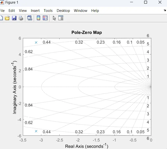
Poles we get :
P1=-3.1416 + 5.4414i
P2= -3.1416 - 5.4414i
Using the command
figure(1);pzmap(G);grid;
Poles are negative left half side of s-plane ; hence the system is stable.
State Space Matrices:
A=[-Bm/J Kt/J;-Kb/L -R/L]; % State Matrix
B=[0;1/L]; % Input Matrix
C=[1 0]; % Output Matrix
D=0; % Feedthrough Matrix
PID Controller:
u(t) = Kp*e(t) + Ki*∫ e(t) dt + Kd * (de(t))/(dt)
i=acker(A,B,poles); % P & D controller values using acker command
%PID Contollers
Kp=i(1);
Kd=i(2);
Ki=150 %Tuned manually
Value of Kp= 38.3133
value of Kd=-2.8584
Model:
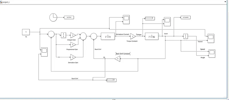
Used Two Transfer Function Blocks to get the Output as Armature Current and Speed.
1st Transfer Function Block assigned (V-Eb)/(L+R) to get Ia
2nd
Transfer Function Block assigned T/ (J+ Bm) to get Speed
Modeled PID controller using the above PID controller Formulae
Used Scope blocks for Visualization of result.
Display Blocks used to see the instant values of parameters
Clock Block to return the time as output signal
To Work Space Block To save the output in workspace
Gain Blocks To return the output signal as gain of input signal.
Integrator Block to get the Integral Output
Sum Block to get the output as summation of the inputs.
As a DC supply is a constant supply respect to time, Chosen Supply Voltage as Constant Block giving 10 V.
Model simulated for 10secs
Solver selected as Fixed Step Size with 0.01 Sampling time and using Runge-Kutta Method for simulation.
Results:
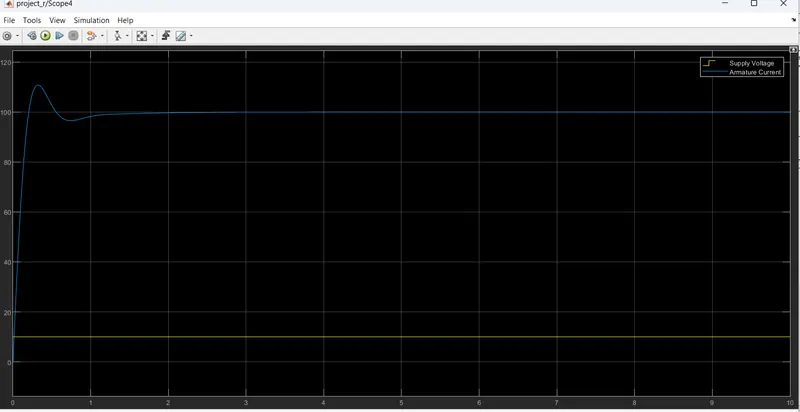
Supply Voltage vs Armature Current.
The Ia initially Overshooted (Inrush Current) to 1.1 kA then about 2 secs it got stabled and the Supply voltage is a constant value set as 10.
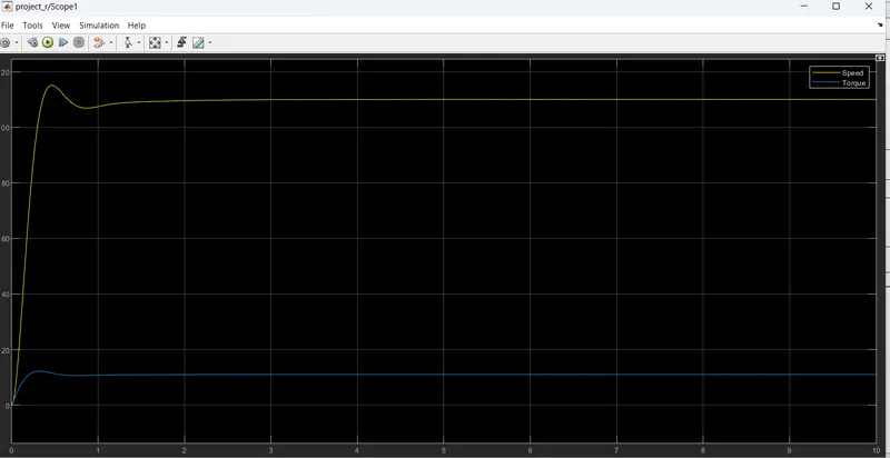
Speed Torque Characteristics:
Torque is 11 n-m and Speed is 10rpm. Both Following stable path after a little initial overshoot
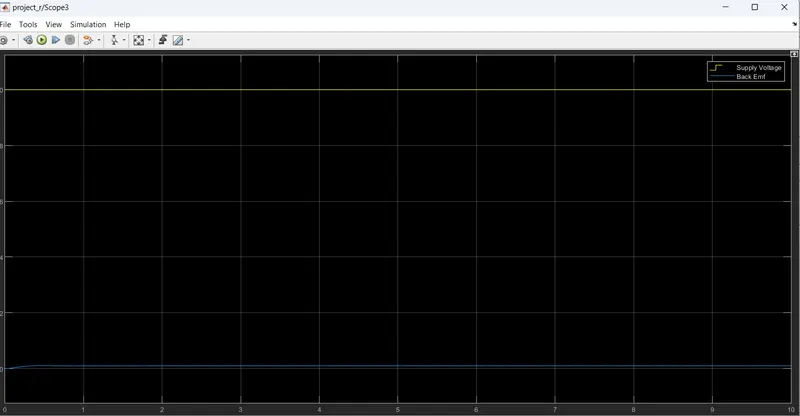
Voltage vs Back Emf
Supply voltage is 10 V and Back Emf 0.1 V/m/s. The Substractive value of these two causes the Mechanical Force in the motor.
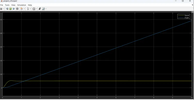
Speed vs Angle:
Speed is 10 rpm maintaining constant path and angular velocity of the rotating parts is about 100rad/s.
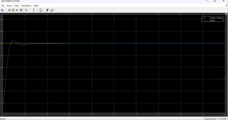
Supply Voltage vs speed:
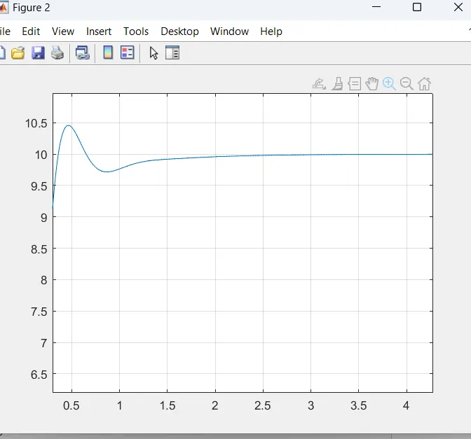
As We can see that 10 V is our supply voltage and our motto is to see Speed is behaving same with respect to Vs or not. From the Scope result we got an overshoot which is less than 5% of Input (10.5) and settling time is about 2.4 secs.
Hence the Control Design objectives have been achieved. We have a stable system as well as stable output with respect to input signal.
From Time Vs Speed Graph, we can also reverify that Overshoot is less than 10.5 and Ts is about 2.4 secs which is desirable.
The raw and required Files have been attached herewith.
Conclusion:
1. Control Design Objectives achieved ✔
2. Speed Control Objective achieved ✔
3.Stability of the System achieved ✔
.