Week-6 Challenge: EV Drivetrain
QUESTION -
1.Which types of power converter circuits are employed in electric and hybrid electric vehicle?
SOLUTION -
Power Converter -
The task of a power converter is to process and control the flow of electric energy by supplying voltages and currents in a form that is optimally suited for user loads.Electric Vehicles (EVs), Hybrid Electric Vehicles (HEVs) and Fuel Cell Electric Vehicles (FCEVs) have been typically proposed to replace conventional vehicles in the near future. An Electric Vehicle is a vehicle that uses a combination of different energy sources, Fuel Cells (FCs), Batteries and Super capacitors (SCs) to power an electric drive system. In EV, one or more energy storage devices assist the main energy source. Thereby the system cost, mass, and volume can be decreased, and a significant better performance can be obtained. Two often used energy storage devices are batteries and Super capacitors.
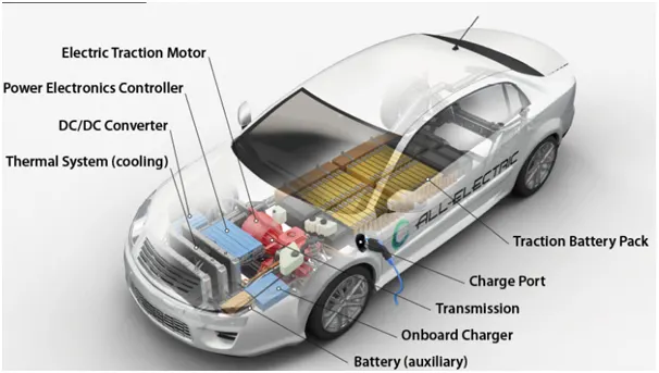
Power electronic converters perform various basic power conversion functions. This converter is a single power conversion stage that can perform any of the functions in AC and DC power conversion systems.
Depending on the type of function performed, power electronic converters are categorized into following types.
- AC to DC = Rectifier: It converts AC to unipolar (DC) current
- DC to AC = Inverter: It converts DC to AC of desired frequency and voltage
- DC to DC = Chopper: It converts constant to variable DC or variable DC to constant DC
- AC to AC = Cycloconverter, Matrix converter: It converts AC of desired frequency and/or desired voltage magnitude from a line AC supply.
AC to DC Convertes or Rectifier:
AC to DC Converters are one of the most important in power electronics.The AC current to DC current conversion process is known as Rectification. The Rectifier convert AC supply into the DC supply at load end connection.The essential components in this rectifier include transformer, switching unit, filter and a control block.
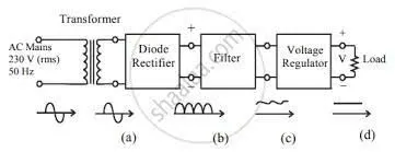
The transformer adjusts the primary AC source supply to the input of rectifier stage. Usually it is a step-down transformer that reduces the supply voltage to a circuit operating range.The rectifier converts the low voltage AC supply into DC supply.The output of the rectifier is pulsating DC as shown in the above fig. and hence it is filtered using filter circuit, which is usually made with a capacitor or a choke.
The filtered output contains some amount of AC in it which is clearly shown in above. Then it is applied to voltage regulator which regultes the output of filter and gives DC output to load. Rectifiers are generally used in PHEV and PEV type vehicles.
DC to AC Converters or Inverters:
These converters are connected between DC source of fixed input, and variable AC load. Most commonly, these DC to AC converters are called as inverters. An inverter is a static device that converts fixed DC supply voltage to variable AC voltage.
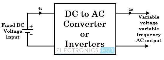
Inverter can used to control speed of the motor by adjusting the frequency of the Alternating current .Inverters have capability to change the torque power by adjusting the alternating current parameters. This conversion from DC to AC along with variable supply is produced by varying the triggering angle to the thyristors. Most of the thyristors used in inverters are employed with forced commutation technique. Inverters can be single phase or three phase inverter depending on the supply voltage. These converters are mainly divided into two groups. One is PWM based inverters and other multilevel inverters.
DC to DC converters or Chopper:
A DC chopper is a static device that converts a fixed input DC voltage to variable DC output or a fixed DC output of different magnitude (which can be lower or higher) than input value.
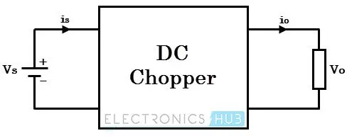
DC/DC converters can be designed to transfer power in only one direction, from the input to the output. However, almost all DC/DC converter topologies can be made bi-directional. A bi-directional converter can move power in either direction, which is useful in applications requiring regenerative braking.We know lights, indicators and other signal generators requires only low voltage (12V or 24 V).So the battery energy (DC type high range) will converted into Low voltage DC by DC to DC converter (Chopper).
The chopper circuit is connected between DC input source and DC load. This chopper consists of power electronic switching devices such as thyristors which are connected in such a way that they produce required DC voltage to the load.DC choppers are mainly used in DC drives, i.e., electric vehicles and hybrid electric vehicles.
AC to AC converter or Cycloconverter:
Ac to Ac converters is used for converting the AC waveforms with one particular frequency and magnitude to AC waveform with another frequency at another magnituide .We know that there are different types of loads that work with different types of power supplies like single phase ,three phase supply ,and the supplies can be differentiated based on the voltage and frequency range also.
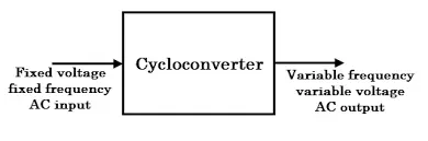
This conversion is mainly required in case of speed controlling of machines ,for low frequency and variable voltage magnitude applications as well.We require a paricular voltage and particular frequency for operating some special devices or machines for speed control of induction motors.
2. An Electric Vehicle's powertrain with 72V battery pack in shown in the diagram below. The duty ratio for acceleration operation is 'd1' and for the braking operation the duty ratio is 'd2'.
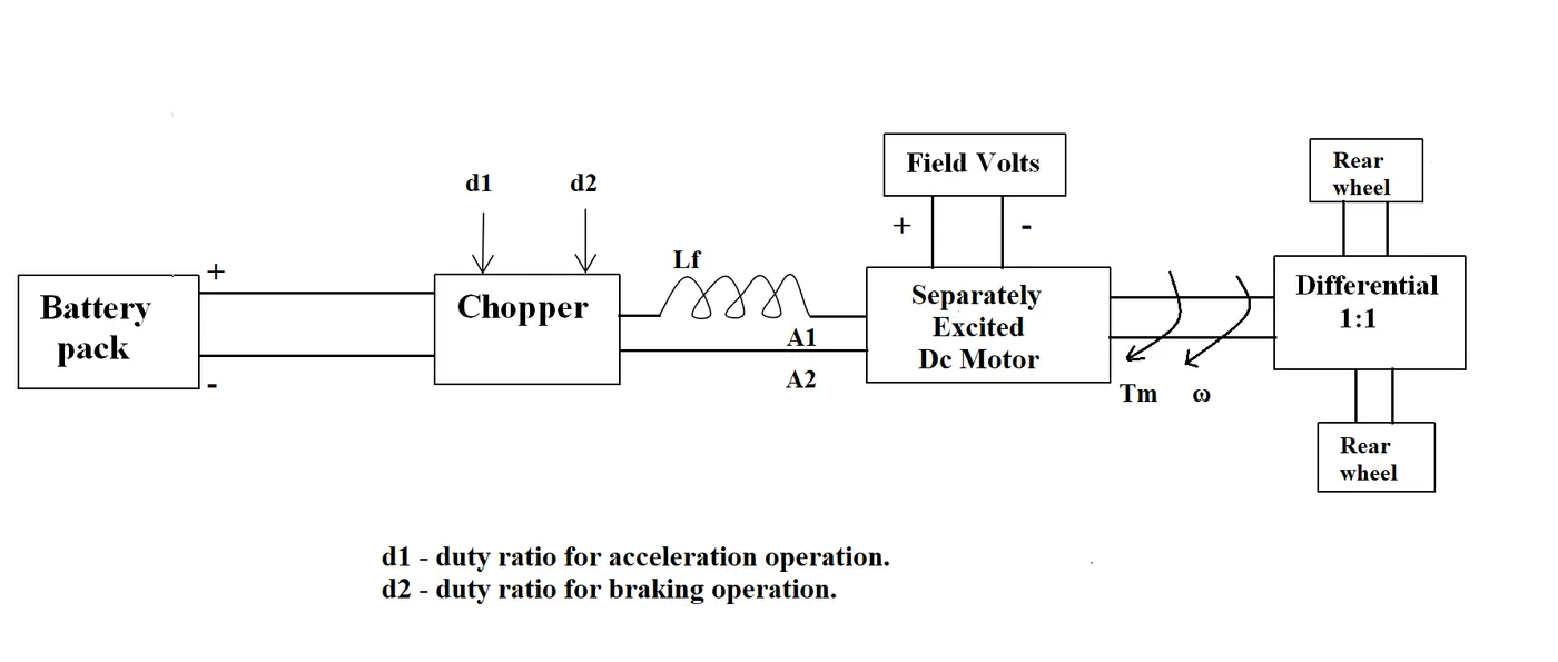
The other parameters of the electric vehicle is given below,
Motor and Controller Parameters:
Rated Armature voltage= 72 V
Rated armature current= 400 A
Ra= 0.5Ω, KΦ= 0.7 Volt second
Chopper Switching frequency= 400 Hz
The vehicle speed-torque characteristics are given by the below equation

What is EV steady state speed if duty cycle is 70%?
SOLUTION -
Vehicle Output Voltage = Battery Voltage(V)*Duty Cycle
= 72*0.7
=50.4 volt
we know, the equation of vehicle torque as,
Torque (T) = ((v*kphi)/R)-((kphi^2*w)/R)
where,
T= torque in Nm
v=Armature voltage in volt
R=resistance in ohm
w=speed rad/sec
kphi=motor constant
solving the equation,
24.7+0.0051*w^2 = ((v*kphi)/R)-((kphi^2*w)/R)
24.7+0.0051*w^2=(50.4*0.7)/0.5-(0.7^2/0.5)*w
70.56-0.98*w=24.7+0.0051*w^2
0.0051w^2 + 0.98w – 45.86 = 0
Above quadratic equation is in the form of ax^2 + bx + c = 0 , which is solved by using the formula as below
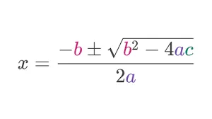
Substituting the equations values in above formula
w = 0.98± ((√ (0.98)^2 – 4*0.0051 * 45.86) )/ 2*0.0051
Here we get w = 38.92 rad/sec or -231.072 rad /sec
since speed can not be negative so, speed(w)=38.92 rad/sec i.e 371 RPM
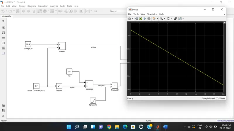
3. Develop a mathematical model of a DC Motor for the below equation using Simulink.
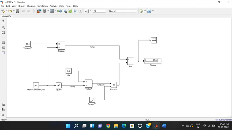
ω= V/Kϕ -Ra/Kϕ^2 .T
SOLUTION -
Below model is made from the above equation. here we consider Voltage (V) as 50.4v ,Armature resistance(Ra)=0.5ohm and Motor constant (Kphi)=0.7. Torque is in the form of Ramp nature. Output obtained from the each block is given in below model.Display shows the final value of the output i.e speed (w).
Output Plot -
4. Refer to the blog on below topic:
Induction Versus DC brushless motors by Wally Rippel, Tesla
Explain in brief about author’s perspective.
Explanation -
Induction Versus DC Brushless Motors -
This blog is about the walley reppel who explain the features and advantages of brushless DC and induction motor.Walley is proponent of electric vehicle , he was engineer at Aeroenvironment .He also worked in jet propulsion laboratory on electric vehicle battery research ,among other projects proponent means someone who is in favor of something.He said the lead acid battery is replaced by lithium and brush DC motor with brushless DC motor or induction motor.
He said that, With brushless machines, the rotor includes two or more permanent magnets that generate a DC magnetic field (as seen from the vantage point of the rotor).And inverter is necessary for the the DC motor otherwise it is useless.
The stators for the 3-phase induction motor and the DC brushless motor are virtually identical. Both have three sets of “distributed windings” that are inserted within the stator core. The essential difference between the two machines is with the rotor.Unlike the DC brushless rotor, the induction rotor has no magnets.
3-phase induction motor is connected to utility type 3-phase power.In contrast, a brushless DC motor produces no starting torque when directly connected to fixed frequency utility power.The limitation of the induction motor is that it can not operate on DC supply.
Both DC brushless and induction drives use motors having similar stators. Both drives use 3-phase modulating inverters. The only differences are the rotors and the inverter controls. And with digital controllers, the only control differences are with control code. (DC brushless drives require an absolute position sensor, while induction drives require only a speed sensor; these differences are relatively small.) One of the main difference author said that much less rotor heat is generated with the DC brushless drive.
Dc brushless drive operate on unity power factor also whereas the best power factor for the induction drive is about 85 percent. He said that as the size of DC brushless motor increase the losses are also increases and proportionaly the efficiency of motor decreased.Whereas in induction motor as size increase it not affect the motor efficiency.
Also induction motors will likely retain a cost advantage over PM machines. He said that induction motor are difficult to control.The control laws are more complex and difficult to understand as compared to DC motor.
Then from all the observation he concluded that, DC brushless drives will likely continue to dominate in the hybrid and coming plug-in hybrid markets, and that induction drives will likely maintain dominance for the high-performance pure electrics.And he predicting that the hardwares of both machines are so much common then DC brushless motor and Induction motor work side by side in the future.