Project - Speed Control of a Direct Current (DC) motor
PROJECT -
AIM - Design a Simulink model for PID Controller of DC motor which regulates the speed to the Desired range.
OBJECTIVE - Buid the model of PID Controller of Dc motor and Verify the results.
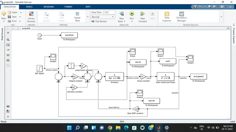
SIMULINK MODEL -
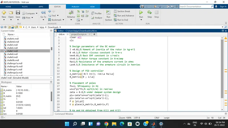
MATLAB SCRIPT -
SCRIPT OUTPUT -
EXPLANATION -
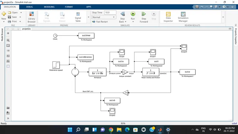
Below fig. shows the DC motor schematic arrangement and according to this schematic repesentation of motor , Simulink model is made which is shown in below .
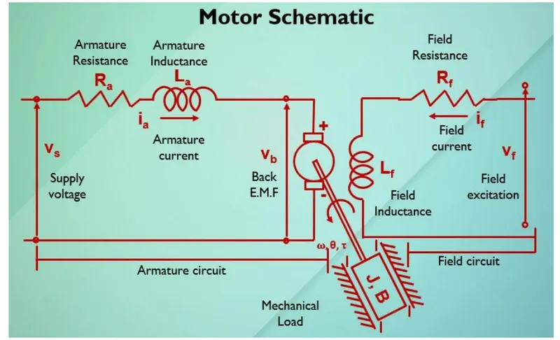
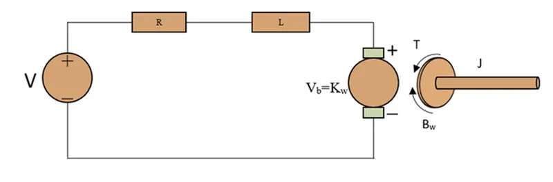
when we apply kirchoffs law to the schematic model of Dc motor we get ,
As per Kirchhoff’s Voltage Law
V = IR + L (di/dt) + Vb
L (di/dt) + IR = V - Kb (dθ/dt) ----------(a)
As per Newtons Law
J (d2θ/dt2) + B (dθ/dt) = KT * I ----------(b)
Converting the above equations to the S domain (Laplace Transform)
Laplace of equ – (a)
LsI(s) + RI(s) = V(s) - Kbsθ(s) ---------(c)
I(s) = V(s) - Kbsθ(s)/Ls + R ----------(d)
Laplace of equ – (b)
Js2 θ(s) + Bs θ(s) = KT * I(s) --------(e)
ωs = s θ(s) = KT * I(s)/Js+B ----------(f)
Substitute I(s) value in equ-(e)
Js2 θ(s) + Bs θ(s) = KT * I(s) ------- (e)
Js2 θ(s) + Bs θ(s) = KT * (V(s) – Kbsθ(s))/ (Ls + R) --------- (g)
s θ(s)[(Js+B) * (Ls+R)] = KTV(s) – KT * Kbsθ(s)
s θ(s)[(Js+B) * (Ls+R)] + KT * Kbsθ(s)= KTV(s)
s θ(s)[(Js+B) * (Ls+R) + (KT * Kb)]= KT V(s)
The transfer function of output angle θ(s) to the input angle V(s) is given by
Ga(s) = θ(s)/V(s) = KT / s[(Ls+R) * (Js+B) + (KT * Kb)] ---------- (h)
The transfer function of the output angle ω(s) to the input angle V(s) is given by
Ga(s) = (s)/V(s) = KT / [(Ls+R) * (Js+B) + (KT * Kb)] --------- (i)
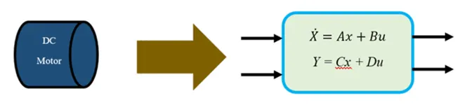
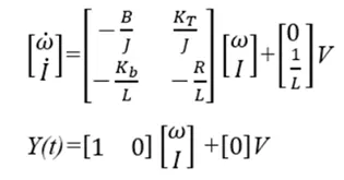
Modeling of a DC Motor with PID controller we need to obtained the State Space equations for the DC Motor. State equations will be derived from equations (a) and (b)
dI/dt = - (R/L) I + (1/L) V – (Kb/L) d/dt
dI/dt = - (R/L) I + (1/L) V – (Kb/L) ω dI/dt
dω/dt= - (B/J) ω + (1/J) KTI
Y(t) = ω = d/dt
A state space representation of the DC motor from the above equations
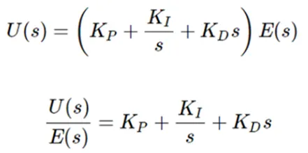
The above simulink model is general model of DC motor it is then implemented by using control gains kp, kd and ki to made a model of PID controller of DC motor. A proportional-integral-derivative controller (PID controller or three-term controller) is a control loop mechanism employing feedback that is widely used in industrial control systems and a variety of other applications requiring continuously modulated control.The mathematically PID controller can be defined by the following equation where e(t) is the error signal with respect to time, Kp, Ki and KD are PID constants.

Apply Laplace transform on both sides.
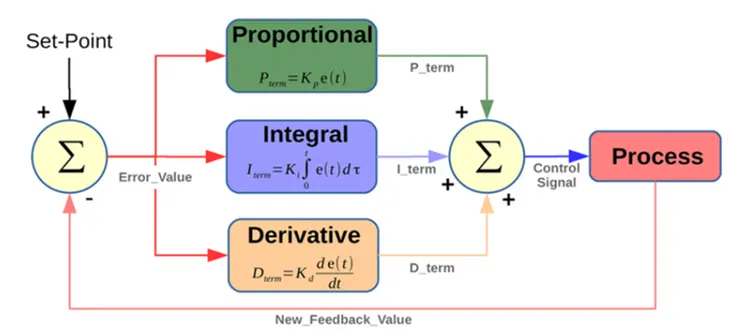
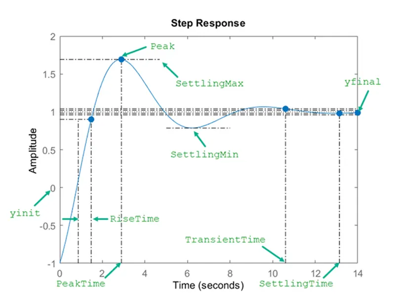
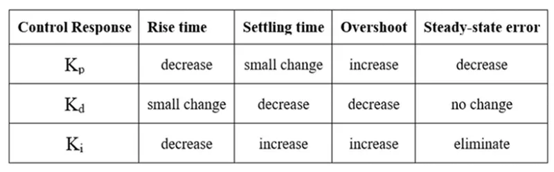
The parameter which is under control must have some properties or be free from some properties such as rise time, settling time, overshoot, and steady-state error. The impact of PID parameters on such properties can be found in the below table.
In Simulink model ,the model is PID controller of Dc motor which regulates the speed. PID controller of Dc motor is similar to the modelling of the Dc motor in some manner but the control mechanism is different.
Ref.speed block indicates any referance input that user wants to regulate is applied to it. So 50 as a referance input is applied to this block. This input is applied to Sum block and output of Sum block is given to the control gain i.e kp(proportional gain) and ki(integral gain). Integrator is connected to the ki gain because it is in integral form. Then they are connected to the Sum1 block.
The output of Sum1 block is given to the Sum2 block which is then given to the Transfer function block i.e Armature. It has armature resistance(Ra) and armature inductance(La) placed in it. It gives the output that is armature current.
After multiplying armature current to torque constant we get Torque given by equation,
T = kt*i where , i= armature current kt= torque constant T= torque
When torque is multipled with the Transfer function block which is rotor inertia and friction we get speed(w) as a output. Back EMF (vb) is related with the speed by the equation,
vb=km (dtheta/dt) where, km=Back EMF constant
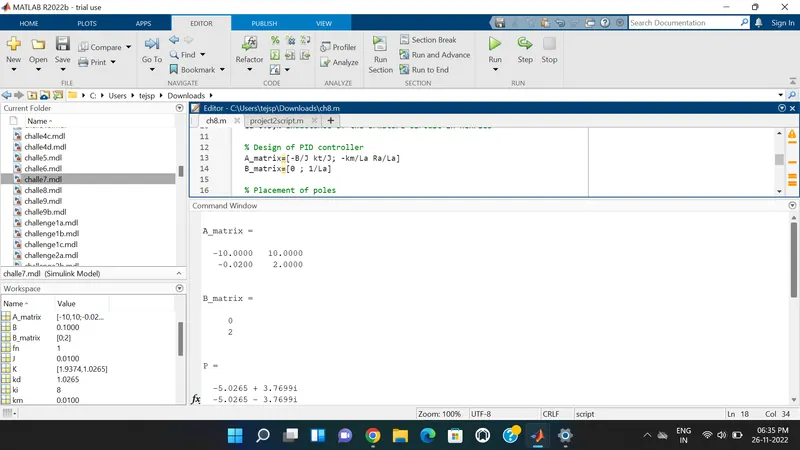
so according to this we get Back Emf(vb) and then it is applied to Sum2 block. From the State space representation of the Dc model we get the A and B matrix which is shown in the Matlab script as well as in command window above.
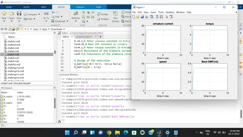
The design parameters of the Dc motor are specified in the script with their units. we are selecting zeta =0.8 (under damped system). By running the Matlab script we get matrix A & B , poles and K.
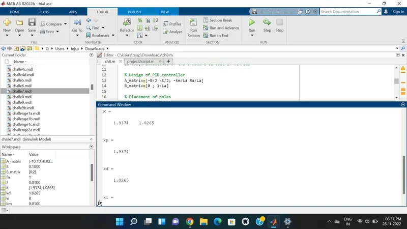
The poles are obtained at left side of S plane so that the system is Stable and we can find the K matrix and also find Kp and Kd values.
kp(proportional gain) is obtained from K(1) which is 1.9374 and Kd(derivative gain) is obtained from K(2) which is 1.0265 . We are considering ki(integral gain)= 8.
Clock is used to get the continuous signal and it's output is obtained to workspace by connecting "out.timer" block. Scope is used for obtaining graphical representation of the output.
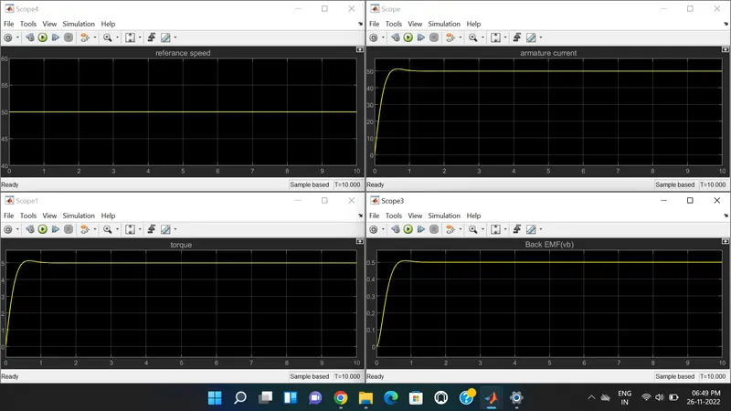
Scopes are connected at different point to obtained armature current, torque, Back EMF(vb), Referance speed and Speed(w).
The stop time for this model is 10 sec. Solver type is ode4(Runge kutta) and step size selected as 0.01.
RESULT -
As the Referance speed selected as 50 so that straight line is obtained on it. Below plot shows the Referance speed, armature current, torque and Back EMF(vb).
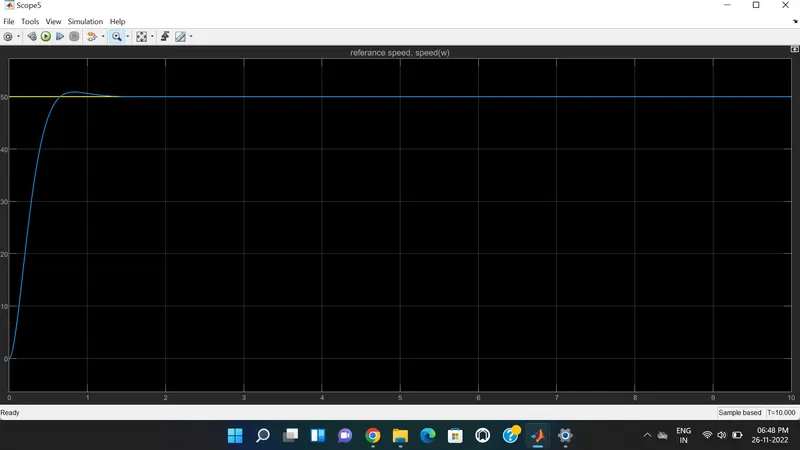
Here , Yellow line indicates referance speed and blue line indicates the speed(w) which is obtained after performing control action and transfer function. We get a small overshoot in the output due to control gains. Settling time is 1.5sec, Overshoot occurs at 50.88 and Steady state error is less than 1%.
CONCLUSION -
In this project , we build the Simulink model of PID controller of DC motor which regulates the speed to the desired and analyzed the response of the system. we also understand the Settling time , Overshoot and Steady state error of the system and its effect on control gain parameters.