Week-6 Challenge: EV Drivetrain
Aim:
1. Which types of power converter circuits are employed in electric and hybrid electric vehicle?
2. An Electric Vehicle's powertrain with 72V battery pack the duty ratio for acceleration operation is 'd1' and for the braking operation the duty ratio is 'd2'. We have to find what is EV steady state speed if duty cycle is 70%
3. Develop a mathematical model of a DC Motor for the given equation using Simulink.
4.
Refer to the blog on below topic:
Induction Versus DC brushless motors by Wally Rippel, Tesla
Explain in brief about author’s perspective.
Requirements:
MATLAB
Simulink
Powertrain Blockset
Objective 1:
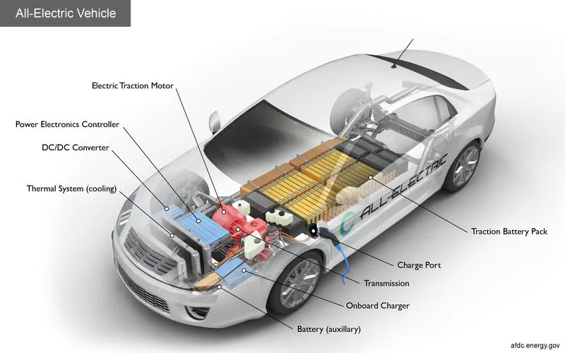
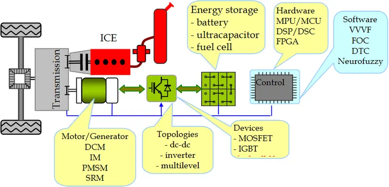
Types of power converter circuits are employed in electric and hybrid electric vehicle.
1. AC to DC Power converters
AC to DC Converters are one of the most important elements in power electronics. This is because there are a lot of real-life applications that are based on these conversions. The electrical circuits that transform alternating current (AC) input into direct current (DC) output are known as AC-DC converters. They are used in power electronic applications where the power input a 50 Hz or 60 Hz sine-wave AC voltage that requires power conversion for a DC output.
The process of conversion of AC current to dc current is known as rectification. The rectifier converts the AC supply into the DC supply at the load end connection. Similarly, transformers are normally used to adjust the AC source to reduce the voltage level to have a better operation range for DC supply.
The rectifier converts the AC supply into the DC supply at the load end connection. There are different types of rectifiers, such as half-wave, full-wave, and bridge rectifiers.
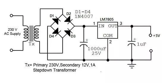
Full Bridge rectifier which consists of four diodes are connected in the form of a bridge. The diode conducts only in one direction, i.e during forward bias. It remains in an off state in another direction, i.e. during reverse bias.
In the above circuit, during the positive half cycle, the diodes D2 & D4 conducts. And during the negative half cycle of the power supply, diodes D1 & D3 conducts. Thus, in this way input AC power is rectified into output DC power. But the problem is DC output power consists of pulses and is not pure DC.
Obtaining Pure DC Waveform
We need to convert the pulsating DC to pure DC. To do that, most of the circuit uses a Capacitors. The capacitor is used to store energy while the input voltage is increasing from zero to its peak value. The energy from the capacitor can be discharged while the input voltage is decreasing from its peak value to zero.
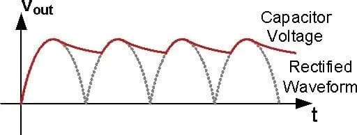
Thus, In this way, we can convert the pulsating DC into pure DC using this charging & discharging process of the capacitor.
2. DC to DC Power converters.
The DC-to-DC converters convert one level of DC voltage to another level. The operating voltage of different electronic devices such as ICs, MOSFET can vary over a wide range, making it necessary to provide a voltage for each device. A Buck Converter outputs a lower voltage than the original voltage, while a Boost Converter supplies a higher voltage.
With the application of DC-to-DC Converters, the circuit’s efficiency, ripple, and load-transient response can be changed. Optimal external parts and components are generally dependent on operating conditions such as input and output specifications. So, while designing the products, the standard circuits must be varied or changed according to and as per the need to their individual specification requirements. Designing the circuit that satisfies the specification and all the requirements needs a great deal of expertise and experience in that field.
The step-up or step-down DC-to-DC Converters are useful in applications where the battery voltage can be above or below the regulator output voltage. The DC to DC converter must be able to operate as a step up or down voltage supplier to provide constant load voltage over the entire battery voltage range through the operation.
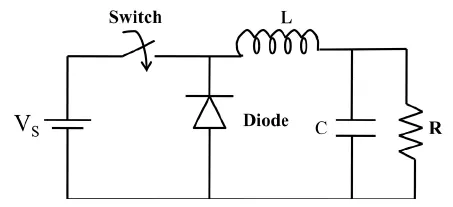
Step-down/Buck Converters
In a typical non-isolated step-down or buck converter the output voltage VOUT depends on the input voltage VIN and the switching duty cycle D of the power switch.
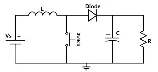
Step-up/Boost Converters
It is used to boost DC to DC converter voltage and it uses the same number of passive components but arranged to step up the input voltage so that the output is higher than that of the input.
Buck-Boost Converters
This converter allows the input DC voltage to be either stepped-up or stepped-down, depending on the duty cycle.
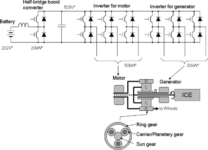
3. DC to AC power converter
DC-to-AC Converters are one of the most important elements in power electronics. This is because there are a lot of real-life applications that are based on these conversions. The electrical circuits that transform Direct current (DC) input into Alternating current (AC) output are known as DC-to-AC Converters or Inverters. They are used in power electronic applications where the power input pure 12V, 24V, 48V DC voltage that requires power conversion for an AC output with a certain frequency.
These are used in numerous applications, including PV systems, battery storage systems, traction drives, variable speed drives, etc. Converting from DC to AC is more complicated because the circuit needs some kind of oscillator that reverses the current direction at the required frequency. Most inverters rely on resistors, capacitors, transistors, and other circuit devices for converting DC Voltage to AC Voltage.
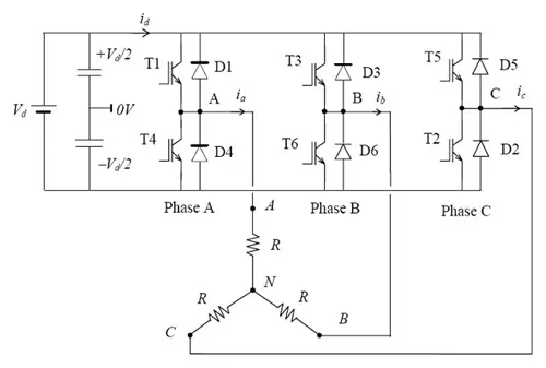
The 3-phase bridge type VSI with square wave pole voltages has been considered. The output from this inverter is to be fed to a 3-phase balanced load. Figure below shows the power circuit of the three-phase inverter. This circuit may be identified
as three single-phase half-bridge inverter circuits put across the same dc bus. The individual pole voltages of the 3-phase bridge circuit are identical to the square pole voltages output by single-phase half bridge or full bridge circuits. The three pole voltages of the 3-phase square wave inverter are shifted in time by one third of the output time period.
Objective 2:
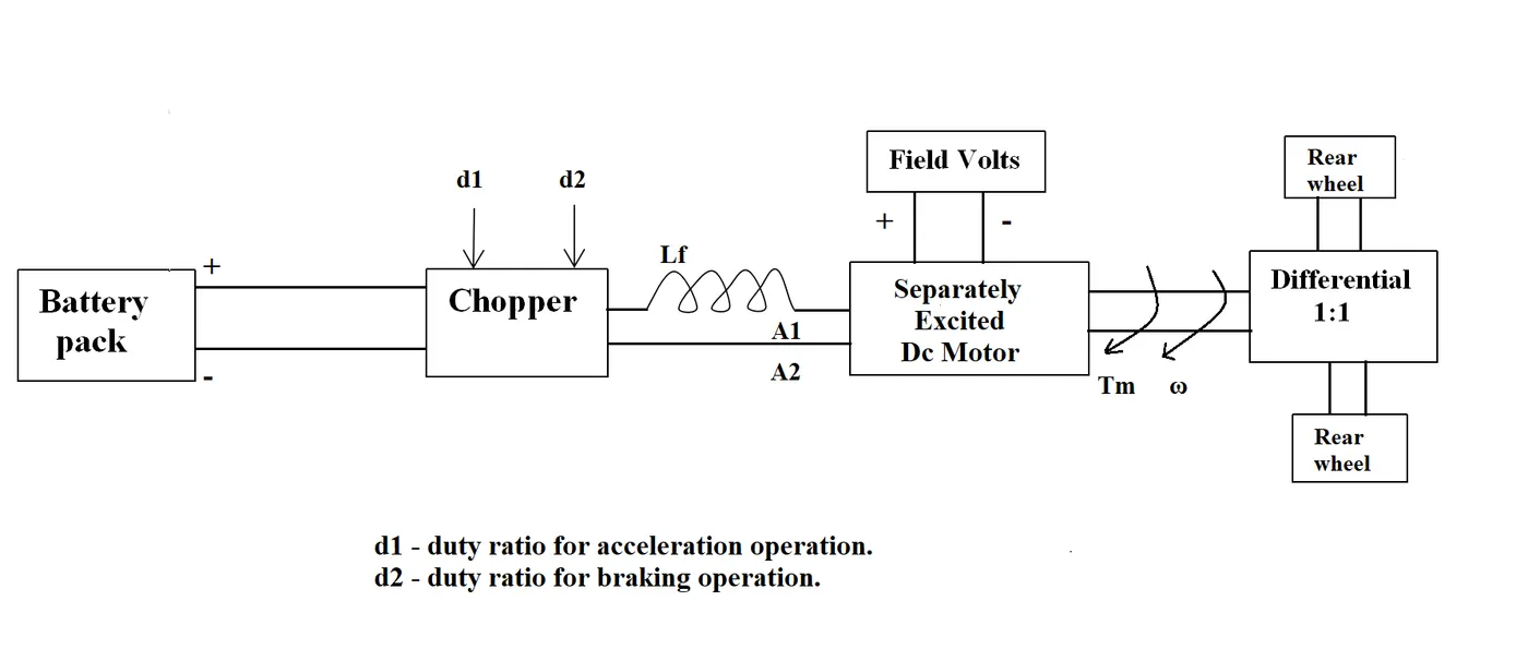
An Electric Vehicle's powertrain with 72V battery pack in shown in the diagram below. The duty ratio for acceleration operation is 'd1' and for the braking operation the duty ratio is 'd2'.
The other parameters of the electric vehicle is given below,
Motor and Controller Parameters:
Rated Armature voltage= 72 V
Rated armature current= 400 A
Ra= 0.5Ω, KΦ= 0.7 Volt second
Chopper Switching frequency= 400 Hz
The vehicle speed-torque characteristics are given by the below equation

What is EV steady state speed if duty cycle is 70%?
solution:
Given
Rated Armature Voltage Ea = 72V
Armature Current = 400A
Armature resistance = 0.5 ohms
Speed torque charactaristics given as
duty cycle = 70%
Voltage = 72*0.7 = 50.4V
We know that equation for speed of the motor is
`T=V((kphi)/(Ra)-(kphi)^2/(Ra)*w)`
`Tm=50.4(0.7/0.5-07^2/0.5)w`
`Tm=70.56-0.98w` - eq(1)
`Tv=24.7+0.005w^2` - eq (2)
equating both equations we get
`24.7+0.0051w^2=70.56-0.98w`
by solving this we get
`0.0051w^2+0.98w-45.86=0`
In order to find roots to solve the above equation which is form of quadratic equation
`ax^2+bx+c=0`
`x=-b+-sqrt((b^2-4ac)/(2a)`
substiture the above value is eqation
`w=0.98+-sqrt((0.98^2-4*0.0051*45.8)/(2*0.0051))`
Steady state angular speed is
`w=38.92`rad/sec.
Objective 3:
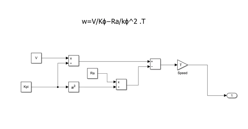
Develop a mathematical model of a DC Motor for the below equation using Simulink.
ω= V/Kϕ -Ra/Kϕ^2 .T
Objective 4:
Refer to the blog on below topic:
Induction Versus DC brushless motors by Wally Rippel, Tesla
Explain in brief about author’s perspective.
Wally Rippel is a long-time proponrnt of electric vehicles. Prior to joining Tesla Motors, he was an engineer at AeroVironment, where he helped develop the EV1 for General Motors and was featured in the documentary movie,Who killed electric car? Wally has also worked for the Jet Propulsion Labaratory on electric vehicle battery research, among other projects. In 1968, as a Caltech undergraduate student, he built an electric car (a converted 1958 Volkswagen microbus) and won the Great Transcontinental Car Race against MIT.
In the world of gas powered vehicles, engines are not all alike. There are flat-heads, Hemis, straight, opposed, and V configurations. And on and on. There is no one best engine type, rather there are different types of engines to suit personal requirements, such as price and performance. This is also true for electric vehicle drives. When He was young there were lead acid batteries, DC brush motors, and contactor controllers but Today, none of these remain. Lead has been replaced by lithium and DC by either DC brudhless or induction. Contactors, meanwhile, have given way to modulating inverters. So, will each of these elements also become obsolete in the near future or is it possible that some “stability” may be at hand. Without a good crystal ball, it is hard to predict the future. His is guess, however, is that we will see both induction and brushless machines “duke it out” for many years to come. Each will have its loyal proponents and religious detractors.
With brushless machines, the rotor includes two or more permanent magnets that generate a DC magnetic field. In turn, this magnetic field enters the stator core and interacts with currents flowing within the windings to produce a torque interaction between the rotor and stator. As the rotor rotates, it is necessary that the magnitude and polarity of the stator currents be continuously varied – and in just the right way - such that the torque remains constant and the conversion of electrical to mechanical energy is optimally efficient. The device that provides this current control is called an inverter. Without it, brushless motors are useless motors.
3 - Phase induction motor was invented by Nikola Tesla sometime before 1889. The stators for the 3-phase induction motor and the DC brushless motor are virtually identical. Both have three sets of “distributed windings” that are inserted within the stator core. The essential difference between the two machines is with the rotor. Unlike the DC brushless rotor, the induction rotor has no magnets – just stacked steel laminations with buried peripheral conductors that form a “shorted structure.” Currents flowing in the stator windings produce a rotating magnetic field that enters the rotor. In turn, the frequency of this magnetic field as “seen” by the rotor is equal to the difference between the applied electrical frequency and the rotational “frequency” of the rotor itself. Accordingly, an induced voltage exists across the shorted structure that is proportionate to this speed difference between the rotor and electrical frequency. In response to this voltage, currents are produced within the rotor conductors that are approximately proportionate to the voltage, hence the speed difference. Finally, these currents interact with the original magnetic field to produce forces – a component of which is the desired rotor torque. When a 3-phase induction motor is connected to utility type 3-phase power, torque is produced at the outset; the motor has the ability to start under load. No inverter is needed.
While 3-phase induction motors have great utility, they also have some severe limitations. They cannot operate from DC; AC is a must. Shaft speed is proportionate to line frequency. Hence, when used with utility power, they are constant speed machines. Finally, when operated from utility power, they have limited starting torque and somewhat limited running peak torque capabilities, when compared to DC type machines. Add an inverter (without any feedback control) and it becomes possible to power an induction machine from a battery or other DC source; variable speed also becomes possible simply by adjusting the inverter frequency. Still, torque performance is low compared with DC machines. Add some feedback loops such that the inverter produces the exact frequency that the motor “desires,” and the induction motor is now capable of competing with DC and DC brushless for vehicle applications.
Back in the 1990s all of the electric vehicles except one were powered by DC brushless drives. Today, all the hybrids are powered by DC brushless drives, with no exceptions. The only notable uses of induction drives have been the General Motors EV-1; AC proopulsion vehicles, including the tzero; and the Tesla Roadster. Both DC brushless and induction drives use motors having similar stators. Both drives use 3-phase modulating inverters. The only differences are the rotors and the inverter controls. And with digital controllers, the only control differences are with control code. One of the main differences is that much less rotor heat is generated with the DC brushless drive. Rotor cooling is easier and peak point efficiency is generally higher for this drive. The DC brushless drive can also operate at unity power factor, whereas the best power factor for the induction drive is about 85 percent. This means that the peak point energy efficiency for a DC brushless drive will typically be a few percentage points higher than for an induction drive, induction machines have no magnets and B fields are “adjustable,” since B is proportionate to V/f (voltage to frequency). This means that at light loads the inverter can reduce voltage such that magnetic losses are reduced and efficiency is maximized. Thus, the induction machine when operated with a smart inverter has an advantage over a DC brushless machine – magnetic and conduction losses can be traded such that efficiency is optimized. This advantage becomes increasingly important as performance is increased. With DC brushless, as machine size grows, the magnetic losses increase proportionately and part load efficiency drops. With induction, as machine size grows, losses do not necessarily grow. Thus, induction drives may be the favored approach where high-performance is desired; peak efficiency will be a little less than with DC brushless, but average efficiency may actually be better.
Permanent magnets are expensive – something like $50 per kilogram. Permanent magnet (PM) rotors are also difficult to handle due to very large forces that come into play when anything ferromagnetic gets close to them.
Author Conclusion is that DC brushless drives will likely continue to dominate in the hybrid and coming plug-in hybrid markets, and that induction drives will likely maintain dominance for the high-performance pure electrics. The question is what will happen as hybrids become more electrically intensive and as their performance levels increase? The fact that so much of the hardware is common for both drives could mean that we will see induction and DC brushless live and work side by side during the coming golden era of hybrid and electric vehicles.