Week-6 Challenge: EV Drivetrain
Que 1:
Ans>
Types of converter used in electric vehicle are:
1. Rectifier AC-DC Converter
2. Inverter DC-AC Converter
3. Chopper DC-DC Converter
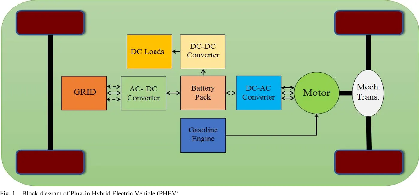
1. Rectifier (AC-DC) Converter:
Rectifier used in electric vehicle for AC grid voltage into DC voltage for charging Battery from AC grid.
Rectifier is optional part while designing vehicle, depend on its used in powertrain charging on vehicle is divide into two types:
Onboard charging- in which rectifier is inside vehicle
Offoard charging- in which Rectifier is placed outside vehicle and direct DC supply given to vehicle for charging battery
2. Inverter (DC-AC) Converter:
Inverter is used in electric vehicle for converting battery DC voltage into AC voltage for supplying motor with AC supply and this converter is also act as controller of motor.
This Inverter used in EV when AC motor is used for running wheel of vehicle.
3. Chopper (DC-DC) Converter:
Chopper is used in electric vehicle for converting Battery high DC voltage into low DC voltage for supplyling volage to DC auxilary load
Que 2:
Ans>
Given:
Motor and Controller Parameters:
Rated Armature voltage= 72 V
Rated armature current= 400 A
Ra= 0.5Ω, KΦ= 0.7 Volt second
Chopper Switching frequency= 400 Hz
Duty cycle= 70%
Torque Equation:
T=k*ϕ*Vo/Ra-(k*ϕ)^2*w/Ra
where, T= Torque
ϕ= Motor Constant
Vo=Supply Voltage
w=Speed of motor
Ra= armature resistance
Vo=0.7*72=50.4 V
T= 0.7*50.4/0.5-(0.7)^2*w/0.5
T=70.56 -0.98*w........1
Given equation is
 ...........2
By equating equation 1 and 2 for steady state condition we get w value as:
70.56 -0.98*w= 24.7 +0.0051*w^2
0.0051*w^2 + 0.98*w-45.86 =0
w=38.91 rad/sec and w =-231.072 rad/sec
Speed cannot be negative so steady state speed at 70 % duty cycle is 38.91 rad/sec
Que 3:
Ans>
Step 1: Created mathematical model of DC motor in MATLAB simulink using equation
ω= V/Kϕ -Ra/Kϕ^2 .T
As shown below:
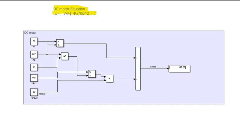
Results:
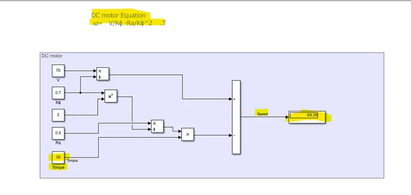
Using Input parameters:
Supply Voltage=70V
K*phi=0.7
Ra=0.5 ohm
And Torque =30 Nm
Output of this model is motor speed so for given input torque of 30Nm Speed is 69.39 rad/sec as shown below:
Que 4:
Ans>
This blog explains about which is best suitable motor for Electric and hybrid vehicle in comparison with Induction versus DC brushless motor
This blog is written by Wally Ripple, who was proponent of electric vehicle engineer working in Tesla and also has experienced in working different projects like: developed EV1 care for General Motors, worked for Jet Propulsion Laboratory and he build electric car which won the great transcontinental electric car rase against MIT.
Then this blog explains about design and working principal of Brushless DC motor and Induction motor as follows:
Brushless DC motor:
The rotor includes two or more permanent magnets that generate a DC magnetic field (as seen from the vantage point of the rotor). In turn, this magnetic field enters the stator core (a core made up of thin, stacked laminations) and interacts with currents flowing within the windings to produce a torque interaction between the rotor and stator. As the rotor rotates, it is necessary that the magnitude and polarity of the stator currents be continuously varied – and in just the right way - such that the torque remains constant and the conversion of electrical to mechanical energy is optimally efficient. The device that provides this current control is called an inverter. Without it, brushless motors are useless motors.
Induction Motor:
the induction rotor has no magnets – just stacked steel laminations with buried peripheral conductors that form a “shorted structure.” Currents flowing in the stator windings produce a rotating magnetic field that enters the rotor. In turn, the frequency of this magnetic field as “seen” by the rotor is equal to the difference between the applied electrical frequency and the rotational “frequency” of the rotor itself. Accordingly, an induced voltage exists across the shorted structure that is proportionate to this speed difference between the rotor and electrical frequency. In response to this voltage, currents are produced within the rotor conductors that are approximately proportionate to the voltage, hence the speed difference. Finally, these currents interact with the original magnetic field to produce forces – a component of which is the desired rotor torque.
Comparison of BLDC and IM discuss in blog as follows:
|
Parameters |
Brushless DC machine |
Induction Motor |
|
Rotor |
Permanent magnet |
Steel lamination with shorted conductor |
|
Starting |
Need to add inverter with phase difference with rotor |
Self-start |
|
DC operation |
Easy to operate on battery |
Cannot operate on DC supply need to add Inverter |
|
AC supply limitation |
- |
When operated with utility power limited running peak torque |
|
Speed control |
Magnetic field |
Changing supply V/f ratio using inverter |
|
Peak torque |
high |
Low compared to BLDC |
|
Sensor required for Speed control |
Position sensor |
Speed sensor |
|
Heat generated and cooling |
Low heat generated and cooling is easy |
High heat generated and cooling is complicated |
|
Power factor |
Unity |
0.85 |
|
Peak efficiency |
High |
Low compared to BLDC |
|
Average efficiency |
low |
High |
|
Losses |
Losses are increased with size and difficult to minimized |
Losses are not increased with size of motor and can be minimized with control |
|
Cost |
As permanent magnets are costly, cost of machine is high |
Cost of machine is low as compared with BLDC |
|
Controlling |
easy |
Controlling is more complex which also added development cost |
So, conclusion of this blog is:
Still no Winner, Brushless DC motor is more suitable to used in hybrid and plug in hybrid motor while Induction motor is more suitable to used in pure electric vehicle. But in future if hybrid vehicle is more electrified then IM demand may be increased and to reduced complexity in controlling BLDC can be used in pure electric vehicle.