Week-6 Challenge: EV Drivetrain
Challenge01:Types of power converter circuits are employed in electric and hybrid electric vehicle.
- There are mainly four types of power converters used in AC and DC signals.
- AC to DC converter.
- DC to DCconverter.
- DC to AC converter.
- AC to AC converter.
1). AC to DC converter:
- Also called as rectifier circuit.
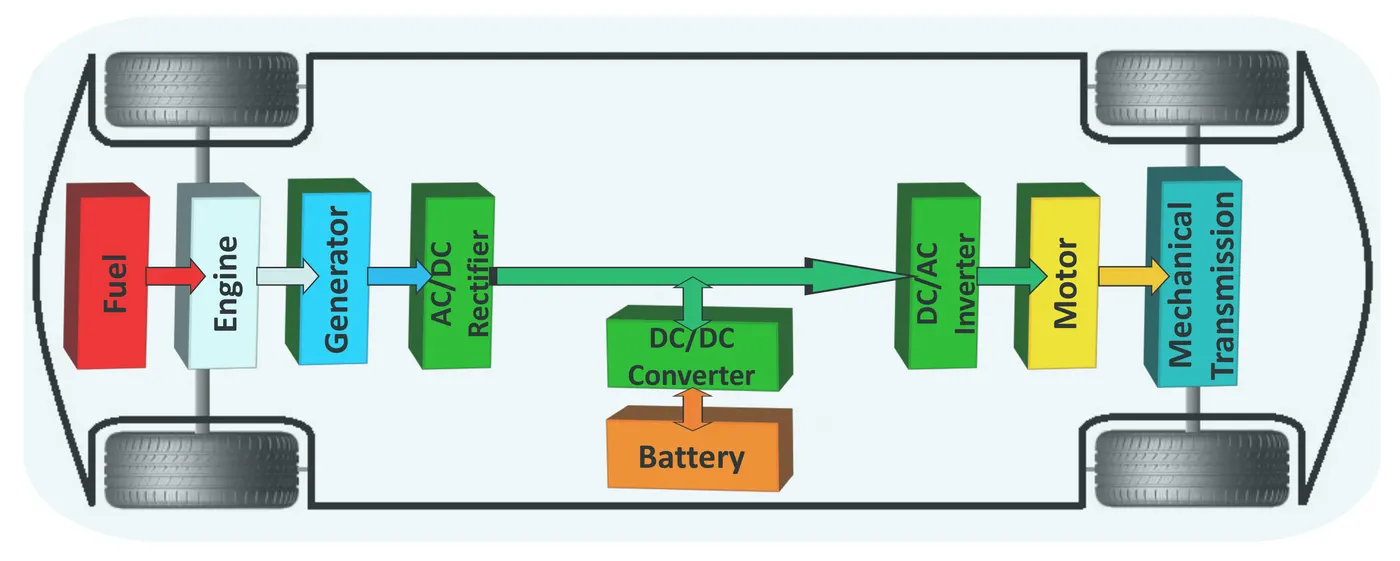
- In HEV battery is charged by engine driven generator, and we all know that a generator produces AC but required DC to charge a battery so in between battery and generator a AC to AC converter is used.
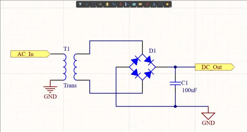
- During positive half cycle of AC ,top right and bottom left diode gets forward biased, and during negative half cycle remaining two diodes are conducting. This arrangeent is such that current and voltage polarity at output terminal remain same during whole cycle and that is how we can get DC output by feeding AC input.
2). DC to DC converter:
- Also called as Chopper circuit.
- Power demand of motor in EV is not always same but battery supplies pure DC so we can not connect battery directly, in order to improve battery performance and durability chopper circuit is used.
- Chopper circuit is placed between Battery and motor, it converts Fixed DC to variable DC by controlled switching operation.
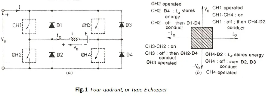
- Chopper is further classified on their different quadrant based operation into three types .
- 1. One quadrant chopper(Type A and B) 2.Two quadrant chopper(Type C and D) 3. Four quadrant chopper.(Type E)
- In four quadrant chopper ,there are four combination of the output current and voltage polarity (++,+-,--,-+).
- Chopper are also classified based on the voltage level 1.Step up chopper 2. Step down chopper.
- In step up chopper , output voltage is greater than input voltage and in step down chopper output voltage is less than input voltage.
2). DC to AC converter:
- Also called as Inverter circuit.
- In EVs, motor used can either be DC or AC induction. So to give supply from battery (which is DC) to Motor it is required to convert DC to AC then there inverter circuits are used.
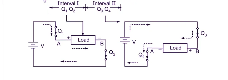
- Inverter circuit uses switches (MOSFET,IGBT) as shown in image below.
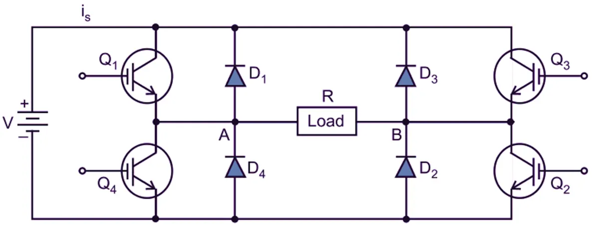
- To get positive output cycle , Q1 and Q2 conducts together, to get negative output cycle Q3 and Q4 are used.
4).AC to AC converter:
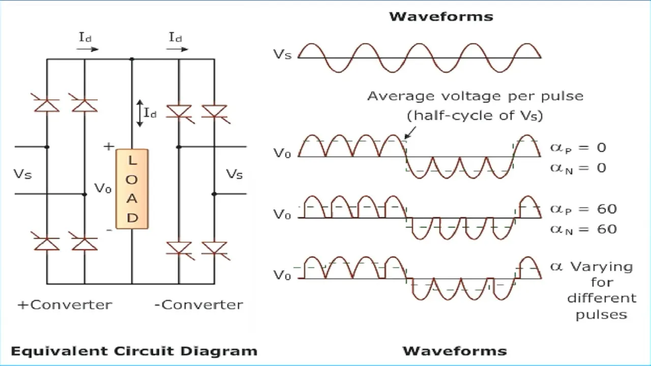
- These types of converter are used in such application where magnitude and frequency of waveform need to be changed at output side.
- Basically they are used in speed control of machines like an induction motor.
- One of the example is a cycloconverter.
- There are various types of cycloconverters like 1-phase to 1-phase , 3-phase to 1-phase and 3-phase to 3-phase.
- In EV these converters are used to control the speed of motor.
Challenge02: EV steady state speed if duty cycle is 70%
- Given:
Rated Armature voltage= 72 V
Rated armature current= 400 A
Ra= 0.5Ω, KΦ= 0.7 Volt second
Chopper Switching frequency= 400 Hz
The vehicle speed-torque characteristics are given by the below equation

- Making Motor speed-torque equation out of given paramerters. We know the relation between motor torque and speed : ω">ω= V/Kϕ">ϕ -Ra/Kϕ">ϕ^2 .T
- Replacing all parameters with their given values we get, w = (72/0.7)- (0.5/(0.7^2))*T.
- Also given that the duty cycle is 0.7 , so if we consider duty cycle the output battery voltage will be d*V = 72*0.7
- Final equation will be: ω">ω = 72 - 1.02.T
- For steady state speed we need to find the intersection point of Torque speed equations of motor and vehicle.
- We will use MATLAB to plot both characteristics curve.
- In MATLAB script just apply both the equations as shown below.
Motor torque speed equation implementation: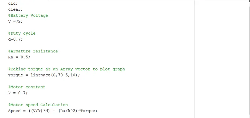
Vehicle Torque speed equation implementation:
Plotting Curves: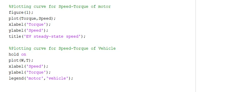
- Run the script to get Curve and then observe the intersection point.
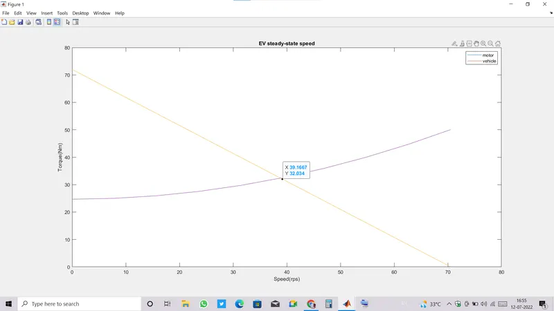
- Intersection point is (39.1667, 32.034) , hence the steady state speed will be X co-ordinate that is 39.2 radian per second.
Challenge03: Develop a mathematical model of a DC Motor for the below equation using Simulink.
ω= V/Kϕ - Ra/Kϕ^2.T
- Open a new model window.
- Now , to apply equation choose blocks accordingly.
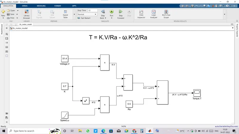
- We will apply motor torque-speed equation as
T = K.V/Ra - ω.K^2/Ra
- For all constant values we use a constant block.
- We want speed as gradually increasing parameter such that torque is calculated for different speeds so it can be done by a Ramp block.
- Model is created by taking appropriate blocks and making proper connection as shown in an image below.
- Run the model to get torque at different speed values.
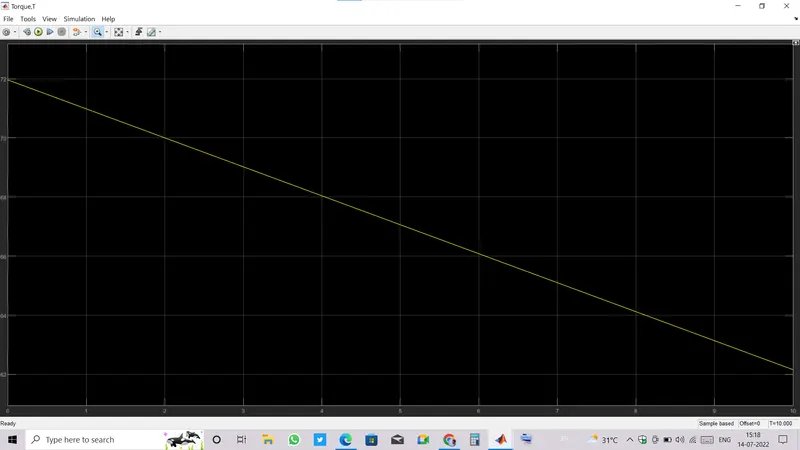
- We can observe that Torque requirement is getting reduced as motor is gaining speed.
Challenge04: Induction Versus DC brushless motors by Wally Rippel, Tesla
- Auther is trying to convey that motor selection for any purpose depends upon the type of application.
- Nowadays ,DC brushless motor is being used widely in HEV, PHEV because of its high torque operation and also due to ease of speed control methods but the constraint is in the core losses, due to presence of Permanent magnets in rotor of DC brushless the flux can not be controlled hence result in core losses.
- These core losses increase as size of motor increases and can not be minimized that's why preferred to use in compact size applications.
- Also the magnetic material is quite expensive.
- On the other hand, Induction motors with 3 phase inverter circuit are also better to use in EVs because magnetic flux can be controlled as there is no permanent magnet used but also have to compromise with torque.
- Also Speed control for induction motor is complex.
- According to auther, any of the motor can not be superior over other. Each has its advantage as well as disadvantage so we can not always go for one.