Week-6 Challenge: EV Drivetrain
Answer to Question 1:
A DC-DC converter converts between voltages of different levels, such as high to low or low to high. This is usually seen between traction batteries and low-voltage power electronics.
These are of several types based on application -
- Buck DC-DC converter - This helps in reducing the voltage from high DC to low DC
- Boost DC-DC converter - This helps in increasing the voltage from low DC to high DC
- Buck-Boost DC-DC converter - This does both increase and decrease voltage levels
An inverter converts DC voltage to AC voltage. It mainly converts DC voltage from traction batteries to AC voltage for traction motors.
A rectifier is also used to convert the AC voltage to DC voltage. This is used primarily for charging systems; between generators and traction Batteries in HEV, and charging ports to traction batteries in EVs.
A schematic representation of the two converters in vehicle architecture is shown below:
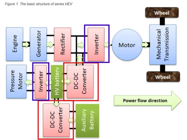
The vehicle architecture is of a Hybrid Electric Vehicle (HEV) where the red rectangular boxes highlight the DC-DC converters while the inverters are shown with purple highlighted boxes.
Reference:
"Power Converters for Hybrid Electric Vehicles"; M. Nandhini Gayathri; https://www.igi-global.com/gateway/chapter/275540#pnlRecommendationForm
Answer to Question 2:
Given Data:
- Rated Armature Voltage ( Vin) = 72 V
- Rated Armature Current ( Ia) = 400 A
- Armature Resistance ( Ra) = 0.5 ohms
- Motor Constant ( Kphi) = 0.7 V/(rad/sec)
- Switching frequency ( f ) = 400 Hz
- Final drive ratio ( id) = 1 : 1
- Duty cycle ( d) = 70 %
Vehicle Characteristic equation:
Tv = 24.7 + 0.0051 * w^2 --------------> ( 1 )
Calculation:
Average voltage during the ON state of the duty cycle : Vavg = Vin * d = 72 * 0.7 = 50.4 V
Motor torque-speed characteristic equation:
Tm = Vavg * Kphi / Ra - Kphi^2 * w / Ra
Tm = 50.4 * 0.7 / 0.5 - 0.7^2 / 0.5 * w
Tm = 70.56 - 0.98 * w ------------------> ( 2 )
Since the final drive ratio is 1 : 1, the motor torque ( Tm ) = torque available at the axle ( Tv)
Solving equation ( 1 ) and ( 2 ) we get,
24.7 + 0.0051 * w^2 = 70.56 - 0.98 * w
0.0051 * w^2 + 0.98 * w - 45.86 = 0
w^2 + 192.16 * w - 8992.16 = 0 ------------------> ( 3 )
The roots of equation ( 3 ) are
w = 38.9145 rad/sec or w = -231.0745 rad/sec
The steady-state speed during the ON state is w = 38.9145 rad/sec => w = 371.61 RPM.
Answer to Question 3:
The equation
omega = Voltage supply / K - Armature Resistance / K^2 * Torque
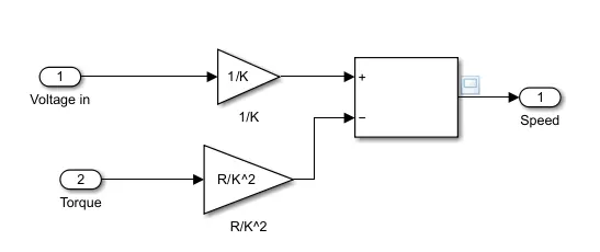
The above system equation is implemented as a sub-system in the simulink model and this is shown below -
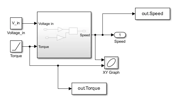
Considering armature resistance = 0.5 ohms, supply voltage = 220 V, and K = 0.8 V / (rad/sec), the plot to this equation is as below:
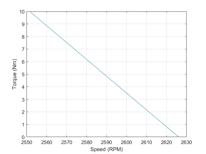
The speed is converted from rad/sec to revolutions per minute. The torque vs speed is linear and inversely proportional.
Answer to Question 4:
|
Induction Motor |
Brushless DC Motor |
|
|
Torque-Speed characteristic |
The shape of the torque-speed characteristics is sinusoidal. |
The shape of the torque-speed characteristics is trapezoidal. |
|
Type of Voltage applied |
AC voltage is applied in 3-phases. |
Pulsed DC voltage is applied. |
|
Structure |
The rotor has steel laminations like a squirrel cage. |
The rotor has permanent magnets. |
|
Efficiency |
It has a lower efficiency. |
It has a higher efficiency. |
|
Slip |
There is slip as the rotor rotates at a lower frequency than the rotating magnetic field at the stator. |
There is no slip as the rotor and rotating magnetic field are at the same frequencies. |
|
Cost |
It is less expensive. |
The cost is higher due to permanent magnets |