Week-6 Challenge: EV Drivetrain
1. Which types of power converter circuits are employed in electric and hybrid electric vehicle?
Electric and hybrid electric vehicles use various types of power converter circuits to manage the flow of electrical energy between the battery motor and other components. These power converters are essential for controlling motor speed torque and efficiency as well as managing battery charging and discharging.
Types of power converter:
DC-AC Inverters:
Converts DC power from the battery into AC power to drive the electric motor which is usually an AC induction motor or permanent magnet synchronous motor (PMSM).
Types:
Single-Phase Inverter:
Used in simpler systems with lower power requirements.
Three-Phase Inverter:
Most common in EVs for providing three-phase AC power to motors for efficient operation and torque control.
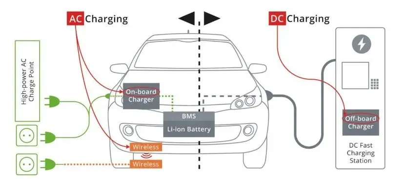
AC-DC Converters (Rectifiers):
Purpose:
Converts AC power (from the grid) into DC power for charging the vehicle’s battery.
Types:
Uncontrolled Rectifiers: Basic type used when control is not needed.
Controlled Rectifiers:
Allows control over the charging process commonly used in regenerative braking to convert AC generated by the motor back to DC to charge the battery.
Onboard Chargers:
Purpose:
The onboard charger manages the process of charging the battery from an external power source It converts AC power from the grid into DC power for the battery.
Types:
Single-Phase Onboard Chargers:
Used in smaller EVs with lower charging power
Three-Phase Onboard Chargers:
Higher power chargers 11kW or more used in larger EVs for faster charging.
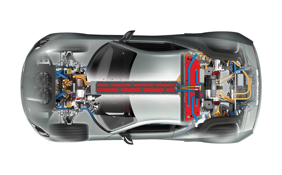
2. An Electric Vehicle's powertrain with 72V battery pack in shown in the diagram below. The duty ratio for acceleration operation is 'd1' and for the braking operation the duty ratio is 'd2'.
The other parameters of the electric vehicle is given below,
Motor and Controller Parameters:
Rated Armature voltage= 72 V
Rated armature current= 400 A
Ra= 0.5Ω, KΦ= 0.7 Volt second
Chopper Switching frequency= 400 Hz
The vehicle speed-torque characteristics are given by the below equation
What is EV steady state speed if duty cycle is 70%?
Solution:
GIVEN DATA: -
The other parameters of the electric vehicle is given below,
Motor and Controller Parameters:
Rated Armature voltage= 72 V
Rated armature current= 400 A
Ra= 0.5Ω, KΦ= 0.7 Volt second
Chopper Switching frequency= 400 Hz
SOLUTION: -
TO FIND VOLTAGE: -
DUTY CYCLE=70%
V=72
DUTY CYCLE=70%=0.7
72*0.7=50.4
V=50.4
TORQUE EQUATION: -
TORQUE T= KΦ/R*[V-KΦ*w]
t= (0.7/0.5) *(50.4-0.7)
=1.4*(50.4-0.7)
=1.4*(50.4-0.7w)
=70.56-0.98w
T=70.56-0.98w
comparing this: -
T=TV
70.56-0.98w=24.7+(0.0051) w^2
24.7+0.0051w^2-70.56+0.98w
here we subtract the constant values
24.7-70.56
=-45.86
0.0051w^2+0.98w-45.86
we solve this into the quadratic equation: -
x=-231.07
x=38.91
3. Develop a mathematical model of a DC Motor for the below equation using Simulink.
`omega`= V/K`phi` -Ra/K`phi`^2 . T
CONSTANT BLOCK:
The Constant block generates a real or complex constant value signal. Use this block to provide a constant signal input. The block generates scalar vector or matrix output depending on the dimensionality of the Constant value parameter.
DIVIDE BLOCK:
The Divide block outputs the result of dividing its first input by its second. The inputs can be scalars a scalar and a non scalar or two non scalars that have the same dimensions. This block supports only complex input values at division ports when all ports have the same single or double data type.
SQUARE BLOCK:
In Simulink, the square block is used to perform the square root operation on the input data signal. The block has control signals that indicate whether the input and output data are valid. The input signal must be a floating-point number, and the block accepts real or complex inputs except for complex fixed-point signals.
RAMP BLOCK:
The Ramp block generates a signal that starts at a specified time and value and changes by a specified rate. The block's Slope start time and Initial output parameters determine the characteristics of the output signal. All must have the same dimensions after scalar expansion.
SUM BLOCK:
In Simulink, the Sum block adds or subtracts inputs, such as scalars vectors or matrices. It can also collapse the elements of a signal and perform a summation.
SCOPE BLOCK:
The Scope block displays its input with respect to simulation time. The Scope block can have multiple axes (one per port) all axes have a common time range with independent y-axes. The Scope allows you to adjust the amount of time and the range of input values displayed.
MODEL EXPLANATIONS:
Open MATLAB and type Simulink in command window. The new tab will open and click create model and the new Simulink model page will open.
Double click the page and type constant and then give enter. Take four constant blocks in the model. And search divide and drag the block add two blocks in the model.
Add one square block. Double click the constant block and type 50.4 in the constant block. The constant block connects to the divide block multiplication symbol. The constant1 block add the value 0.7 then connect the divider symbol in the divider block.
The constant 2 block add the value 0.5, the constant3 block add the value 0.7. Add the one more divide block. The constant 2 block connect divide1 multiplication symbol in divide block. The constant3 block connect to the square block and the square block output connect to the divide block in divider symbol line.
Add the one product block in the Simulink model. Add one more ramp block in model. The ramp block connects the product block. The divider1 output connect the product block. Add one sum block in the model add symbol +ve and -ve in the block.
The divide block output connects the sum +ve symbol. The product output connects the -ve symbol in the model. Add one scope in the model. The sum block output connects the scope block. The model stop time is 10.0.
4. Refer to the blog on below topic:
Induction Versus DC brushless motors by Wally Rippel, Tesla
Explain in brief about author’s perspective.
In Wally Rippel's analysis comparing induction motors to brushless DC (BLDC) motors for electric vehicles he highlights key differences in their design efficiency and practical applications.
Principle:
Induction Motor:
Works on the principle of electromagnetic induction where current in the rotor is generated by the rotating magnetic field of the stator. This magnetic field induces current in the rotor without the need for physical contacts or brushes.
Brushless DC Motor (BLDC):
Operates by electronically switching currents in the stator coils to create a rotating magnetic field that directly interacts with permanent magnets on the rotor allowing for highly efficient torque generation without brushes.
Efficiency and Performance:
Induction Motor:
Generally, less efficient at lower loads due to inherent losses, such as slip which is the difference between the rotor’s speed and the stator’s magnetic field. However induction motors are robust perform well at high speeds and are known for their durability and reliability.
BLDC Motor:
Typically, more efficient especially at low to moderate loads because they have lower electrical losses. The efficiency is high across a wide range making them particularly attractive for applications where energy conservation is a priority.
Thermal Management:
Induction Motor:
Tends to produce more heat due to higher copper and core losses, especially under high loads. Efficient cooling systems are often required, adding to design complexity and cost.
BLDC Motor:
Produces less heat in comparison because of lower rotor losses, especially at low speeds. This lower heat generation is advantageous in smaller spaces and can lead to a more compact design.
Cost and Complexity:
Induction Motor:
Generally, more economical in larger high-power applications where efficiency at high speeds is critical. However, they require a variable frequency drive (VFD) for speed control, adding complexity and cost.
BLDC Motor:
More expensive due to the use of rare-earth magnets in the rotor. However, they require less complex speed control systems compared to induction motors and their efficiency and performance often offset the initial cost in certain applications.
Applications in Electric Vehicles:
Induction Motors:
Used in the Tesla Model S and early EV known for high performance and durability. The flexibility of the induction motor especially at high speeds and loads made it an ideal choice for performance electric vehicles.
BLDC Motors:
Often found in newer EVs and hybrid applications where energy efficiency at low to medium speeds is prioritized. BLDCs also perform exceptionally well in applications with frequent starts and stops.