Week-6 Challenge: EV Drivetrain
1) Which types of power converter circuits are employed in electric and hybrid electric vehicle?
Answer:-
The functions of the power converter circuit in the motor drive are:
- Transfer electrical energy from a source that could be of a given voltage, current at a certain frequency and phase as the input
- To an electrical output of desired voltage, current, frequency and phase to the motor such that the required mechanical output of the motor is achieved to drive the load
- Controller regulates energy flow through feedback coming from the sensor block
- Signals measured by sensors from the motor are low-power, which are then sent to the controller
- Controller tells the converter what it needs to be doing. A closed-loop feedback system is the method of comparing what is actually happening to what the motor should be outputting, then adjusting the output accordingly to maintain the target output
Power electronic converters perform various basic power conversion functions. This converter is a single power conversion stage that can perform any of the functions in AC and DC power conversion systems.Depending on the type of function performed, power electronic converters are categorized into following types.
- AC to DC = Rectifier: It converts AC to unipolar (DC) current
- DC to AC = Inverter: It converts DC to AC of desired frequency and voltage
- DC to DC = Chopper: It converts constant to variable DC or variable DC to constant DC
- AC to AC = Cycloconverter, Matrix converter: It converts AC of desired frequency and/or desired voltage magnitude from a line AC supply
1.ac to dc Converters:
ac-dc converters are shown in Fig. 1.2. The converter of Fig. 1.2(a) is used to get dc supply of fixed voltage. from the ac supply of fixed voltage. Such a converter is known as uncontrolled rectifier. Converters, of Fig. 1.2(b) to (j) allow a variable voltage dc supply to be obtained from the fixed voltage ac supply. In converters of Figs. I.2(b) and (c), a stepless variation of output voltage can be achieved by controlling firing angle of converter thyristors by low power signals from a control unit. Converter of Fig. 1.2(b) is a two quadrant converter in the sense that it is capable of providing variable dc voltage of either polarity with positive current. However, converter of Fig. 1.2(c) is a single-quadrant converter (positive voltage and current). Converters of Fig. 1.2(b) and (c) produce harmonics both on dc and ac side and have low power factor for low dc voltages. The converters of Fig. 1.2(d), (e) and (f) operate at unity fundamental power factor.
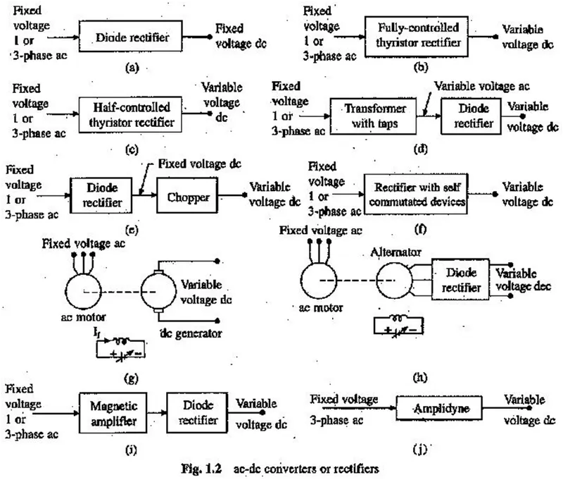
The output voltage in converter 1.2(d) is changed by applying mechanical force. Few discrete steps of dc voltage can only be obtained. In converter of Fig. 1.2(e) output voltage can be varied steplessly by controlling the duty ratio of semiconductor devices of the chopper by low power electrical signals from a control unit. The converter of Fig. 1.2(0 is a controlled rectifier employing self-commutated device such as power transistors, IGHTs and GTOs. It can be a single or two quadrant converter depending on the circuit. When connected in antiparallel, converters of Figs. 2(b) and (f) can provide four quadrant operation (variable voltage and current of either polarity). In ac to dc converter of Fig. 1.2(g),. the output voltage can be controlled by controlling field current of the generator from a control unit (amplifier) of higher power level than the control units of converters of Figs. 1.2(b), (c), (e) and (0. This can operate in all four quadrants. Because of the two rotating machines, it has a number of disadvantages: bulky, heavy, noisy, less efficient, slow response, expensive and requires special foundation. Disadvantages associated with commutator and brushes of file dc generator (Fig. 1.2(g)) are removed in converter of Fig: 1.2(h). However, this converter can operate in a single quadrant only. Some very old equipments may also employ ac to dc converter of Figs. 1.2(i) and (j) employing magnetic amplifier and amplidyne respectively. Magnetic amplifiers and amplidynes are controlled from low power dc signals.
2.AC Voltage Controllers or AC Regulators:
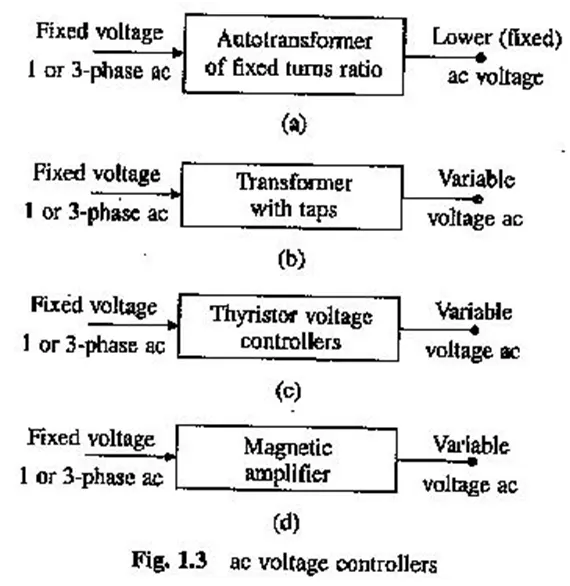
ac voltage controllers (Fig. 1.3) are employed to get variable ac voltage of the same frequency from a source of fixed ac voltage. Voltage controller of Fig. 1.3(a) gives a fixed (smaller) ac voltage supply. The autotransformers capable of giving variable output voltage are not employed due to sliding contacts. Variable ac voltage with few discrete steps is obtained from the controller of Fig. 1.3(b). The control is exercised by a mechanical force. The output voltage and source current are sinusoidal. Converter of Fig. 1.3(c) employs a thyristorised voltage controller. Stepless control of the output voltage can be obtained by controlling firing angle of converter thyristors by low power signals from a control unit. Output voltage and source current have harmonics and power factor is poor at low output voltages. Few old drives may employ magnetic amplifier to get variable voltage ac from fixed voltage ac. Because of high cost, weight and volume, and poor efficiency they have been replaced by thyristor voltage controllers in almost all applications.
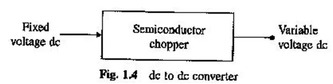
3.Choppers or dc-dc Converters (Fig. 1.4):
They are used to get variable voltage dc from a fixed voltage dc and are designed using semiconductor devices such as power transistors, IGBTs, GTOs, power MOSFETs and thyristors. Output voltage can be varied steplessly by controlling the duty ratio of the device by low power signals from a control unit.
4.Inverters:
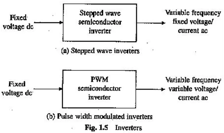
Inverters are employed to get a variable frequency as supply from a dc supply. Stepped-wave inverters of Fig. 1.5(a) can be designed to behave as voltage source or current source. Accordingly they are known as voltage source or current source inverters. For the control of ac motor, voltage/current should also be controlled along with frequency. Variation in output voltage/current can be achieved by varying the input dc voltage. This is achieved either by interposing a chopper in between fixed voltage dc source and the inverter or the inverter may be fed from an ac-dc converter from among those of Figs. 1.2(b), (c) or (f). Output voltage and current have stepped waveform, consequently they have substantial amount of harmonics Variable frequency and variable voltage ac is directly obtained from fixed voltage dc when the inverter is controlled by pulse-width modulation (PWM) (Fig. 1.5(b)). The PWM control also reduces harmonics in the output voltage. Inverters are built using semiconductor devices such as thyristors, power transistors, IGBTs, GTOs and power MOSFETs.. They are controlled by, firing pulses obtained from a low power control unit. In the past variable frequency supply used to be obtained from a frequency changer employing a rotating machine. Such schemes have become outdated due to numerous disadvantages.
5.Cycloconverter
Cycloconverter (Fig. 1.6) converts fixed voltage and frequency ac to variable voltage and variable frequency ac. They are built using thyristors and are controlled by firing signals derived from a low power control unit. Output frequency is restricted to 40% of supply frequency in order to keep harmonics in the output voltage and source current within acceptable limits.

2) An Electric Vehicle's powertrain with 72V battery pack in shown in the diagram below. The duty ratio for acceleration operation is 'd1' and for the braking operation the duty ratio is 'd2'.The other parameters of the electric vehicle is given below,
Motor and Controller Parameters:
Rated Armature voltage= 72 V
Rated armature current= 400 A
Ra= 0.5Ω, KΦ= 0.7 Volt second
Chopper Switching frequency= 400 Hz
The vehicle speed-torque characteristics are given by the below equation

What is EV steady state speed if duty cycle is 70%?
Answer:-
Now we know the equation of torque:
T= (V*k/R)- ((k^2*w)/R)
now compare the above equation of torque with given eqaution in data.
24.7+(0.0051)w^2=(V*k/R)- ((k^2*w)/R)
now put the values in above equation which is already given in data,
24.7+(0.0051)w^2=(72*0.7/0.5)-((0.7^2*w)/0.5)
70.56-0.98w=24.7+(0.0051)w^2
0.0051w^2+0.98w-45.86=0
now use quadratic equation
x= [-b+-sqrt(b^2-4*a*c)]/2*a
=[-0.98+-sqrt((0.98^2)-4*0.0051*(-45.86))]/2*0.0051
we will get tqo values
38.5rad/sec or -231.08 rad/sec
so steady state speed at 70% duty cycle is 38.5 rad/sec.
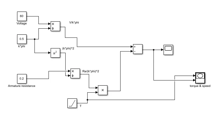
3)Develop a mathematical model of a DC Motor for the below equation using Simulink.
ω= V/Kϕ -Ra/Kϕ^2 .T
Answer:-
Matlab Model:-
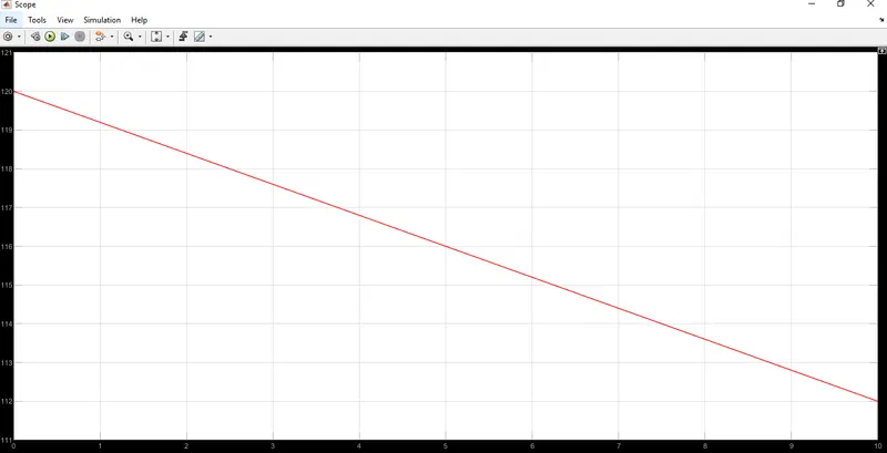
Simulation Result:-
Torque VS Speed:-
X-Axis:- Torque
Y-Axix:- Speed
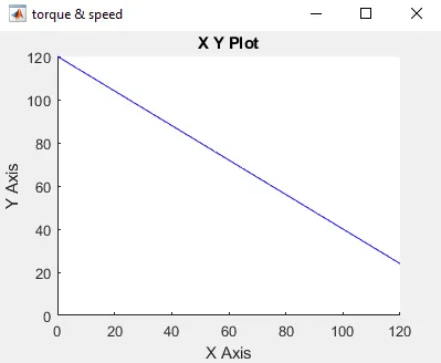
We can observe from the graph that when the speed of motor increases then torque decreases and vise versa.
4)Refer to the blog on below topic:
Induction Versus DC brushless motors by Wally Rippel, Tesla
Explain in brief about author’s perspective.
Answer:
In the above block the author has tried to compare the Brushless DC motor and Induction motors by discussing their advantages and disadvantages.
Brushless DC motor contains the permanent magnets to produce the main flux for the machine while the induction motor is using copper windings.
Brushless DC motor cannot run without the inverter where induction motor can directly run from the supply.
When induction motors are driectly connected with power supply they will run at constant speed as per the equation Ns=120f/P and Ns=(1-s)N.Hence we can use it for variable speed requirement. Also when operated from utility power, they have limited starting torque and somewhat limited running peak torque capabilities, when compared to DC type machines.
Hence the inverter is required for induction motor to get variable speed and torque requirements.
Control techniques is different for both the motors,DC brushless drives require an absolute position sensor, while induction drives require only a speed sensor.
Less heat is generated from DC Brushless motor as compared to induction motor, hence less heat losses in DC Brushless motor.
Permanent magnets are expensive. Their handling is complex and difficult. Chances of mechanical damage. Also the manufacturing of permanent magnets are not that much available across the world( for eg, in india we need to import the permanent magnets which is very costly).
Author has concluded that, Brushless DC motors are suitable for hybrid electric vehicle and induction motors are suitable for pure electric vehicles.