Week-6 Challenge: EV Drivetrain
EV LIVE BATCH 16 STUDENT
1.Types of power converter circuits are employed in electric and hybrid electric vehicle.
An Electric Vehicle is a vehicle that uses a combination of different energy sources, Fuel Cells (FCs), Batteries and Supercapacitors (SCs) to power an electric drive system as shown in Fig. 1. In EV the main energy source is assisted by one or more energy storage devices. Thereby the system cost, mass, and volume can be decreased, and a significant better performance can be obtained.
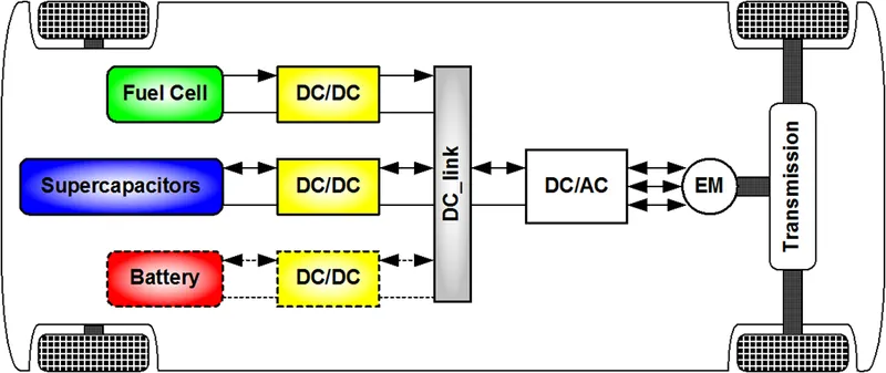
- Types of converters used in Electric vehicle.
1.Non-isolated converters
- The non-isolated converters type is generally used where the voltage needs to be stepped up or down by a relatively small ratio.
- There are five main types of converter in this non-isolated group, usually called the buck, boost, buck-boost, Cuk and charge-pump converters.
- The buck converter is used for voltage step-down, while the boost converter is used for voltage step-up. The buck-boost and Cuk converters can be used for either step-down or step-up. The charge-pump converter is used for either voltage step-up or voltage inversion, but only in relatively low power applications.
2.Isolated converters
- Usually, in this type of converters a high frequency transformer is used. In the applications where the output needs to be completely isolated from the input, an isolated converter is necessary.
- There are many types of converters in this group such as Half-Bridge, Full-Bridge, Fly-back, Forward and Push-Pull DC/DC converters All of these converters can be used as bi-directional converters and the ratio of stepping down or stepping up the voltage is high.
3.Electric vehicle converters requirements
- In case of interfacing the Fuel Cell, the DC/DC converter is used to boost the Fuel Cell voltage and to regulate the DC-link voltage. However, a reversible DC/DC converter is needed to interface the SCs module. A wide variety of DC-DC converters topologies, including structures with direct energy conversion, structures with intermediate storage components (with or without transformer coupling), have been published.
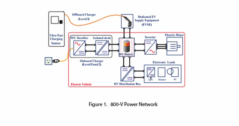
- Boost Converter( Rectifier): To Charge the battery of vehicle by converting AC supply to DC
- Bridge rectifier is used to convert AC supply to output DC.
2. An Electric Vehicle's powertrain with 72V battery pack in shown in the diagram below. The duty ratio for acceleration operation is 'd1' and for the braking operation the duty ratio is 'd2'.
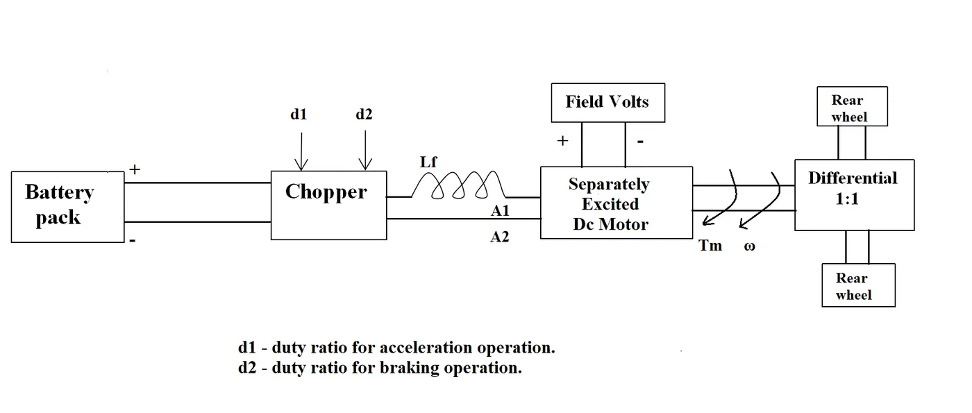
The other parameters of the electric vehicle is given below,
Motor and Controller Parameters:
Rated Armature voltage= 72 V
Rated armature current= 400 A
Ra= 0.5Ω, KΦ= 0.7 Volt second
Chopper Switching frequency= 400 Hz
The vehicle speed-torque characteristics are given by the below equation

What is EV steady state speed if duty cycle is 70%?
AIM:Finding EV steady state speed if duty cycle(d) is 0.7? for following parameters.
Battery Voltage(Vb)=72v
Motor Armature Resistance(Ra)= 0.5Ω
motor Constant(kϕ)=0.7=k
Vehicle speed-Torque equation(τv)=24.7+0.0051ω2
Motor speed-Torque equation(τm)=kVoRa−k2Raω--------------1
At 70% duty cycle (Vo)=Vb⋅d=72*0.7
Vo=54.2
By substituting all values in equation----1, we get as
τm=0.7⋅54.2.0.5−0.720.5ω
τm=70.56−0.98w
At Steady State; τm=τv
By this :
24.7+0.0051ω2=70.56−0.98ω
We get an quadratic equation:
0.0051ω2+0.98ω−45.86=0
By solving above quadratic equation we get real roots
ω=−231.07&ω=38.91
Negative value is not valid
Hence
Steady State Speed of EV at 70% duty cycle is
ω=38.91radsec
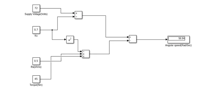
3. Develop a mathematical model of a DC Motor for the below equation using Simulink.
ω=Angular speed of shaft.
V=Supply Voltage
Ra=Armature resistance
k$=Motor constant
τ=load torque
Simulink Model
4. Refer to the blog on below topic:
Induction Versus DC brushless motors by Wally Rippel, Tesla
Explain in brief about author’s perspective.
Author Wally Rippel describes the advantages and disadvantages of BLDC and Induction motors.And tries to predict the which motor will be the best solution for EV's and HEV's.
- Here some of the points discussed on it.
|
Brushless DC Motor |
Induction motors |
|
1.Inverter is needed to Rotate the rotor with constant torque
2. High torque can be generated by varying supply voltage 3.Less heat is generated and easily cooled. 4. As motor size increases both Copper and iron losses also increases and due to this efficiency will decrease. 5.Unity PF can be achieved for small Range EV's. 6. Field strength( Flux) is not adustable as Permanent Magnets were used. 7. High Cost due to Permanent magnets are used. |
1. Inverter is needed to achieve variable frequency and to get supply from Battery.
2. Torque is limited to an extent due to heat produced by electro magnetic field in rotor. 3.Difficult to control Temperature and and Speed. 4. Losses can be controlled and attain maximum efficiency. 5. Maximum PF for an Induction motor is 0.85. 6.Field strength(Flux) is adjustable by varying voltage levels. 7. Low Cost compare to DC machines. |
- By this we cannot come to an conclusion which is best for EV's. Because at last end consumer requirement will be High Performance, Low cost and Maintainence.
- Both will be in use Side by side as there is no much difference between BLDC and Induction motors due to following factors.
- Both have Similar Stator construction.
- Both Requires Inverters.
- Both have Sensors For BLDC: Hall effect sensor, Induction Motor: Speed Sensors
Conclusion: In future Era Both motors will play a key role in Development of EV's.