Week -2
AIM:
- To make a Simulink model of Doorbell using solenoid block
- Use a thermistor to sense the temperature of a heater & turn on or turn off the fan as per the given conditions
TASK 1
- To make a Simulink model of Doorbell using solenoid block with a following details
- In the above arrangement, when the switch is closed the electromagnet receives electrical power from the battery and pulls the metal arm to hit the bell producing sound.
- Create a situation where the switch is closed for 2 seconds and then released. Observe the physical movement of the plunger.
- Assume remaining parameters
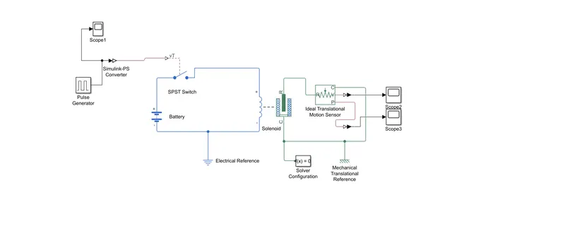
The above block shows the model of doorbell using simulink model. The purpose of blocks are given in detail
- Pulse generator: It is used to generate a square wave pulse at a regular intervals. Parameters are amplitude, period, pulse width, phase delay and to determine the shape of the output waveform
- Scope: To dispaly the signal genearation during simulation
- SPST (single pole single throw)switch: The switch is externally connected to Vt.If the Vt value is greater than threshold then the switch is closed or else switch will be open
- Battery:It is a stored electrical charge used for the circuit
- Elecrtical Reference:Used for the electrical ground
- Solenoid:It act like a magnet while carrying a current so the port R will come in contact with the port C as shown in the above figure
- Solver configuration:It specify the solver parameter that your model needs before going for the simulation
- Mechanical translational reference: It represents the reference point or a frame to all mechanical translational ports
- Ideal translational motion sensor:It acts as a motion sensor in a mechanical translational system it converts two mechanical translational nodes in to a control signal propotional tovelocity or signal
- PS-simulink converter: It converts physical input signal to simulink signal output
WORKING:
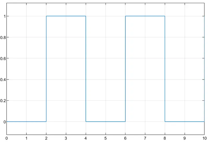
- Pulse generator creates an input signal of pulse width with 1 unit amplitude, 4sec period, having 50% pulse width with 2sec delay for the model
- Then we attach scope to compare input and output signal
- Now the input of Pulse generator connected to simulink converter-PS which is connected to SPST switch
- After recieving the physical signal through Vt , it compare the threshold value .If it is greater than the threshold value then the switch will be closed, or else it remains open
- After the electric circuit is closed then the solenoid will be energised throgh the battery
- As the solenoid charged up the port R pulls towards the port C, Which refers the ringing bell
- Mechanical translational reference connected to the port R of the solenoid to understand the position of the velocity of the plunger of the solenoid
- To record its position and velocity PS-simulink converter converts physical input signal to simulink signal output after connecting the scope we can record it for the simulation duration
RESULT
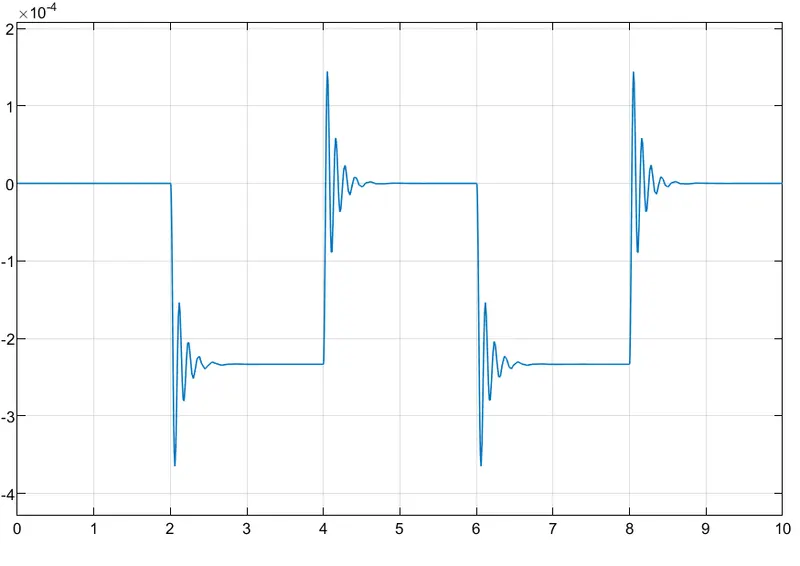
- Pulse value VS Time
2.Velocity VS Time
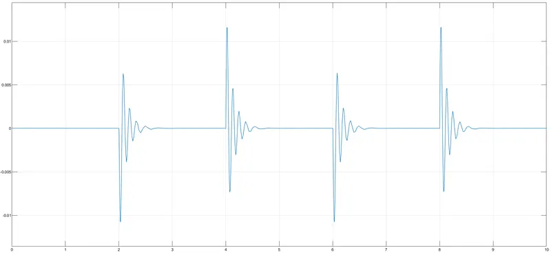
3.Position VS Time
CONCLUSION:
Finally we conclude that , when the pulse generator amplitude is 1, then the plunger will moved and whwn the amplitude returns 0, the plunger moves to original position and in this time interval, because of low damping value it undergoes several oscillation before coming tothe original position.
TASK 2
AIM:
Use a thermistor to sense the temperature of a heater & turn on or turn off the fan as per the given condition below
Temperature source: 20 °C from 0 to 10 seconds, 27 °C from 10 to 30 seconds, 23 °C from 30 to 50 seconds
Fan conditions: ON if the temperature above 25 °C, OFF otherwise
THEORY:
The name thermistor is a shortening of the words thermal resistor. It is essentially a thermally sensitive resistor, giving a change in resistance for a change in temperature.Thermistors can be used in many ways, enabling the temperature of the medium surrounding the device or the device itself to alter its resistance. This can then be detected by the equipment and used for everything from broad temperature sensing to overload cut-outs and many more ideas.
Types of thermister:Positive temperature coefficient (PTC thermistor) This type has the property where the resistance increases with increasing temperature, i.e. the value of k is positive.
Negative temperature coefficient (NTC thermistor) This type of thermistor has the property where the resistance decreases with increasing temperature, i.e. k is negative. The term NTC thermistor is widely used in datasheets and component data.
SIMULINK MODEL:
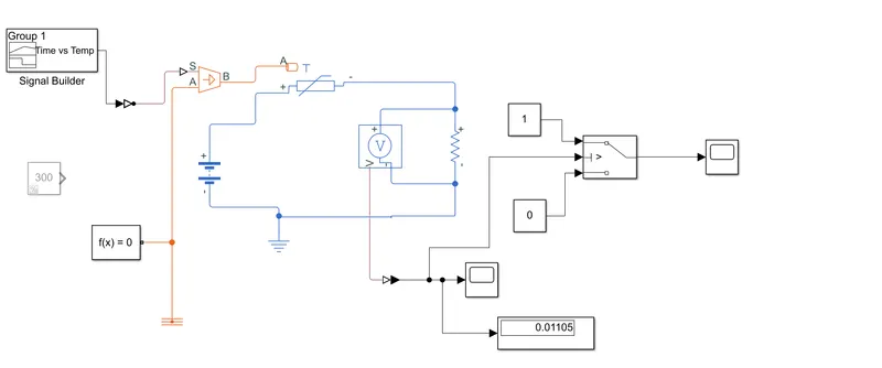
BLOCKS USED:
Signal builder
Temperature controlled sensor
Solver configuration
Thermister
Switch
PS Simulink converter
Display
Scope
Electrical Reference
Constant
Voltage sensor
Resistor
Battery
WORKING
In this simulation, the input is givren to the signal builder as per the given condition.Then it is given to the controlled temperature source,here it is maintaining the temperature difference, without considering how much heat it is providing in the system,and it is then given to the thermister, here in the input according to temperature condition and the battery source is used to give required amount of voltage to the system and voltage sensor is used to sence the voltage and it is connected parallel to the resistor. Then the whole setup is connected to a scope to observe the output waveform. Then the circuit is given to switch and the threshold value is set according to the given condition and the output is observed in the waveform.
OUTPUT WAVEFORM:
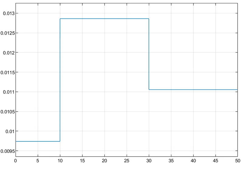
At Temp 25 degree ,From 0 to 30 sec fan is on ,Off otherwise
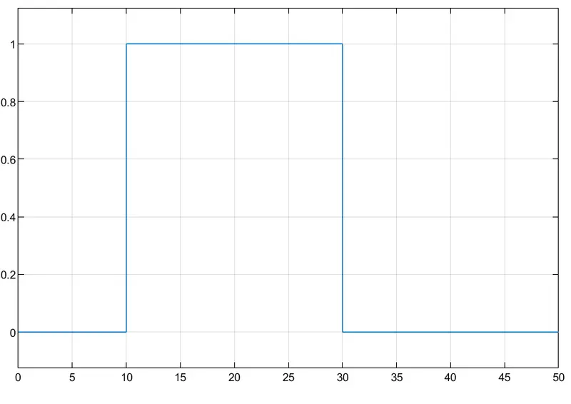
Temperature source: 20 °C from 0 to 10 seconds, 27 °C from 10 to 30 seconds, 23 °C from 30 to 50 seconds