Project
FINAL PROJECT
AIM:
To study and analyse the BAJA AII-Terrain Vehicle (ATV) using MATLAB and Simulink
Objective:
To prepare a technical report explaining the model properties BAJA AII-Terrain Vehicle (ATV) and also explaining the results in 4 different model set ups that are,
- Study the BAJA AII-Terrain Vehicle (ATV) model without a dashboard
- Study the BAJA AII-Terrain Vehicle (ATV) model with a dashboard
INTRODUCTION
An all-terrain vehicle (ATV), also known as a quad, quad bike, three-wheeler, or four-wheeler, is defined by the
American National Standards Institute (ANSI) as a vehicle that travels on low pressure tires, with a seat that is straddled by
the operator, along with handlebars for steering control. An ATV that abides by certain rulesets that are devised by the SAE
for a competition is known as BAJAS. BAJA SAE is an intercollegiate competition organized by Society of Automotive
Engineers (SAE) to design, build and race off-road vehicles. Chassis is an important part of the BAJA vehicle that supports
body and other different parts of the vehicle. It also surrounds and protects the occupant in case of impact and roll over
incidents and also gives the aesthetics of the vehicle.
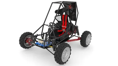
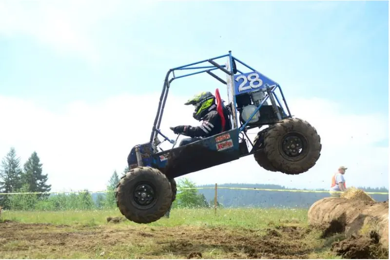
The goal in Baja SAE racing is to design build and race off road vehicle that can withstand the harshest elements of rough terrain. The vehicle used in Baja SAE Racing are often similar in appearance to dune buggies.These are multiplr dynamic events, usually four per event,as well as a single four hour endurance race.The dynamic events includes hill climbs chain pull,rock crawls and suspension and traction events.The Baja vehicle with CVT transmission is being evaluated and discussed here.
Major and Crucial component
- CVT:
A continuously variable transmission (CVT) is an automatic transmission that can change seamlessly through a continuous range of gear ratios. This contrasts with other transmissions that provide a limited number of gear ratios in fixed steps.The system improves the economy and performance of the electric powertrain, while maintaining the smooth and comfortable character of the electric motor. This is how a CVT works for an electric car
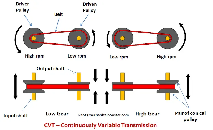
As we can see in the below figure according to the given speed the gear is shifting from one another
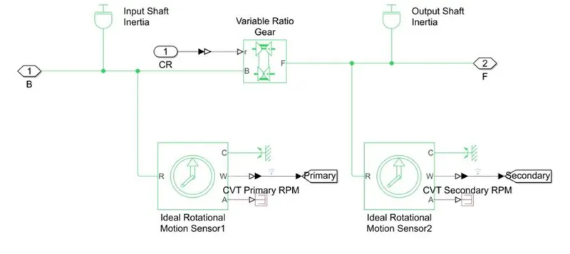
The variable gear arrangements of CVT in this model is represented by the variable ratio gear box
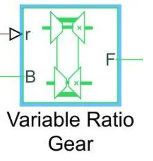
Where
B - Base pulley
F - Follower pulley or Driven pulley
r - Variable transmision ratio(input)
2.Vehicle body:
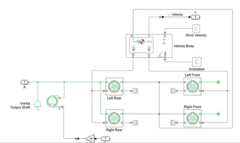
Two -axel vehicle with logitudinal dynamics and motion and adjustable mass,geometry and drag properties.The vehicle can have the same or different number of wheels on each axle. For example two wheels on the front axle and one wheel on the rear axle.The vehicle wheels are assumed identical in size. The vehicle can also have a centre of gravity (CG)that is at or below the plane of travel.
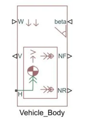
In the Above blocks the parameter are given below
- NR-Rear axle normal force(N)
- NF-Front axle normal force(N)
- Beta-Road incline angle (rad)
- H-Horizontal motion
- V-Longitudinal velocity (m/s)
- W-Head wind speed(m/s)
3.Generic Engine
The generic engine block represents a general internal combustion (IC) engine which is a type of Compresion Ignition(CI -Diesel) or spark ignition (SI PETROL). The speed torque and speed power parameter are provided by the designer
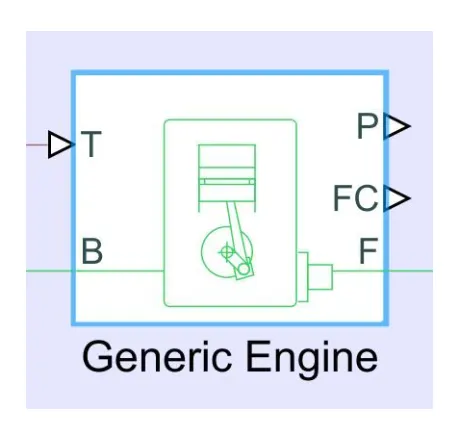
Where,
- B-Rotational Conserving Port representing the engine block
- F-Rotational Conserving Port representing the engine crankshaft
- T-Physical signal input port specilyzing the normalized engine throttle level
- P-Physical signal output port reporting the instaneous engine power, in W
- FC-Physical signal output port reporting the fuel consumption rate in kg/sec
4.Simple gear:
The simple gear is a combination of a driver and driven gear where the speed is reduced by the gear ratio, It is defined as the ratio of Follower Gear speed to Base Gear Speed
Simulink is block is given by
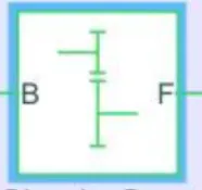
Where
- B-Base Gear or Driver Gear
- F-Follower Gear or Driven Gear
5.Tires and Brakers:
The vehicle body is connected to 4 tires each per axle to move the vehicle according to the power input to the axle
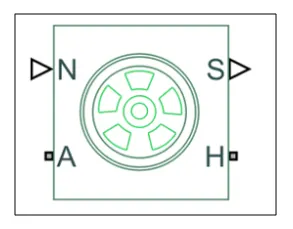
Where
- N-Normal Force
- S-Tire slip
- A-Axle
- H-Mechanical translational port associated with the wheel hub that transmits then the thrust generated by the tire to the remainder of the vehicle
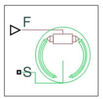
5. Double shoe Brake
Where
- S-Rotational Conserving Port associated with the rotating drum shaft
- F-Physical signal input port associated with the applied actuating force
I. Study the BAJA ATV model without a dashboard
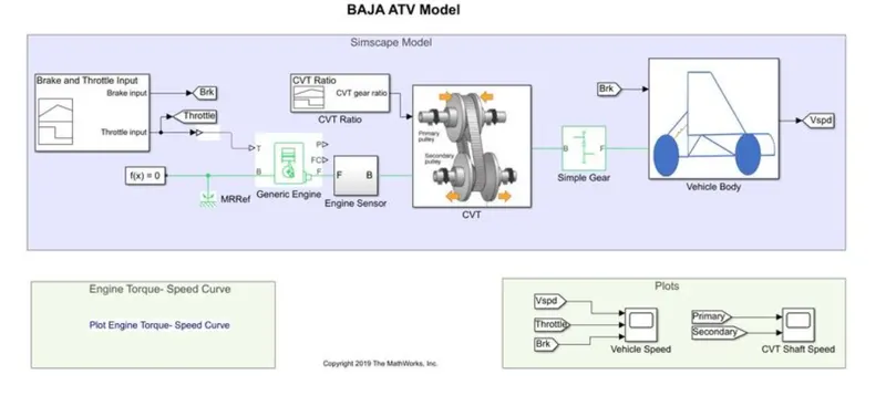
Simulink Model
CVT Set up block
Vehicle Body
Inputs:One signal builder block is used to create signals for brake and throttle and another one is used to create the need CVT ratio
Throtle and Brake input
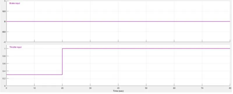
The brake input remained at zero value for the entire simulation.The initial throttle was given 0.3 value and after 20sec it was given value 1
CVT Ratio
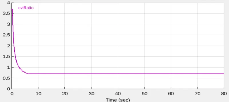
CVT Ratio has been varied over a range 3.7 to 1.8 values through out the simulation
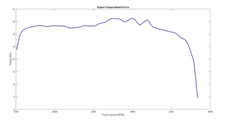
The entire Torque-Speed characteristics can be given by the foloowing graph:
Output Result:
Vehicle speed variation with Throttle and Brake inputs
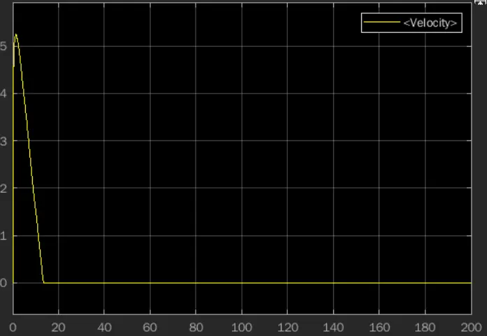
From the graph we can see, that the vehicle attains its maximum speed of 5.1km/Hr at a full throttle =1; at the 120th second and then the speed remains constant.The brake input value is zero,hence it does not affect velocity
CVT primary and secondary speed
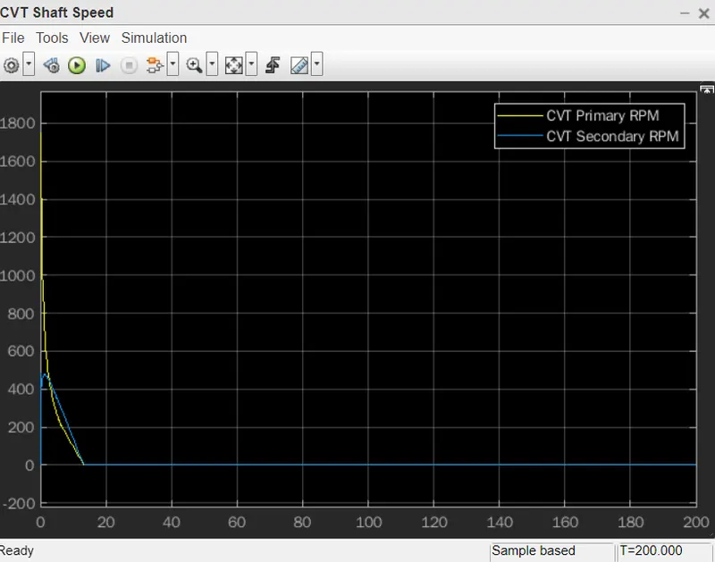
These graph shows the variation in angular velocity in primary(Input)and Secondary(output)shaft of the variable gear transmision system.These values defer from the gear ratio. i.e, if the gear ratio changes the values of both the system changes
II.STUDY THE BAJA ATV MODEL WITH A DASHBOARD
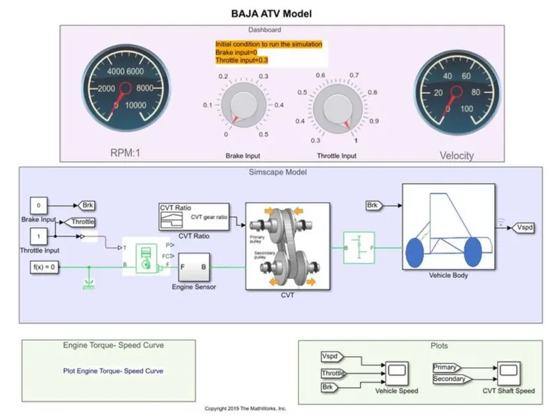
In this model, We have a dashboard that contains knobs to control the throttle and brake input.In this case the inputs are not provided using the signal builder, the knob is provided to control both the inputs in real time for user.One can vary as they want to and will get the according to that
OUTPUT RESULT
Vehicle speed variation with throttle and brake inputs
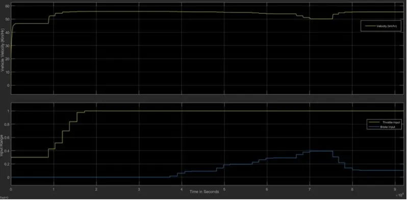
The graph shows that the input were given manually to observe the desired variations and the vehicle speed according to that. the throttle is increased to 0.3 to 1 in an increasing staircase manner and brake was applied at different points of time after the throttle gets value 1.Increasing the throttle input increases the speed over time and settles at 55km/hr, but after the instance wher the brake was applied and there is a decresing a vehicle velocity, the brake value of 0.4 was the highest so the graph properly justify the vehicle behaviour
CVT primary and secondary speed
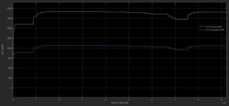
Here we have both the CVT primary and secondary RPMs, the initial increases and settlement were for throttle value 0.3 when there is no brake applied at.After that the behaviour in the results of variation in both the inputs .After the time the throttle is having a constant is 1, all variations basically results from the application of the brake.The downsteps are when the brake is applied and the immediate upsteps are the result of releasing the brake.
`````````````````````````````````````````````````````````````````````````````````````````````````