Week - 4
- Implement control logic of a “washing machine” using Stateflow as per given sequence:
- If the power supply is available, the system gets activated
- If the Water supply is not available, stop the process & indicate through LED
- Soaking time should be 200s followed by Washing time of 100s.
- Then rinsing happens for next 20s & dryer runs for 50s
After all the processes have completed turn on the finished LED
2. Make a Simulink chart for the “Gear shift” logic as per below conditions:
Speed Range(kmph) Gear
0 to 15 1
16 to 25 2
26 to 40 3
41 to 60 4
Above 61 5
Give speed input while the simulation is running & display the gear number.
TASK1
- Implement control logic of a “washing machine” using Stateflow as per given sequence:
- If the power supply is available, the system gets activated
- If the Water supply is not available, stop the process & indicate through LED
- Soaking time should be 200s followed by Washing time of 100s.
- Then rinsing happens for next 20s & dryer runs for 50s
After all the processes have completed turn on the finished LED
THEORY
A washing machine (laundry machine, clothes washer, washer, or simply wash) is a home appliance used to wash laundry. The term is mostly applied to machines that use water as opposed to dry cleaning
There are different types of washing machines available mainly
- Semi-Automatic top-loading.
- Fully Automatic top-loading
- Front-loading washing machine/ washer and dryer combo.
- Front-loading washing machine/ Stackable with separate washer and dryer
- Integrated washing machine.
- Compact washing machine aka portable washing machine.
MODEL
Below simulink image shows the washing machine model
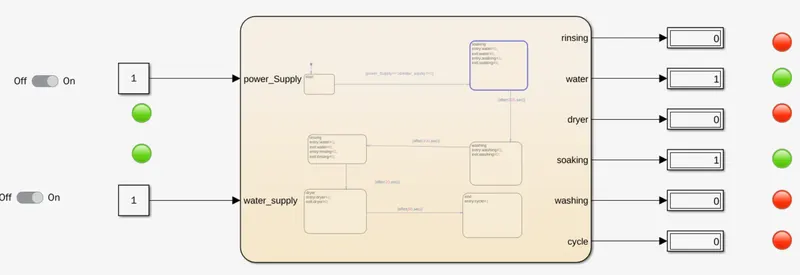
Blocks used
Constant
Slider Switch
Display
State Flow Chart
Lamp
WORKING MODEL:
- According the given control logic we need two input that is water_supply and power_supply by using the constant block we obtained the input
- By using the slider switch we can control on and of status of the input signal
- Then for the machine to work according for the given condition the control logic stateflow block chart is used
- Now as per the given conition to the input and as per the condition given in the state flow chart the control logic is created
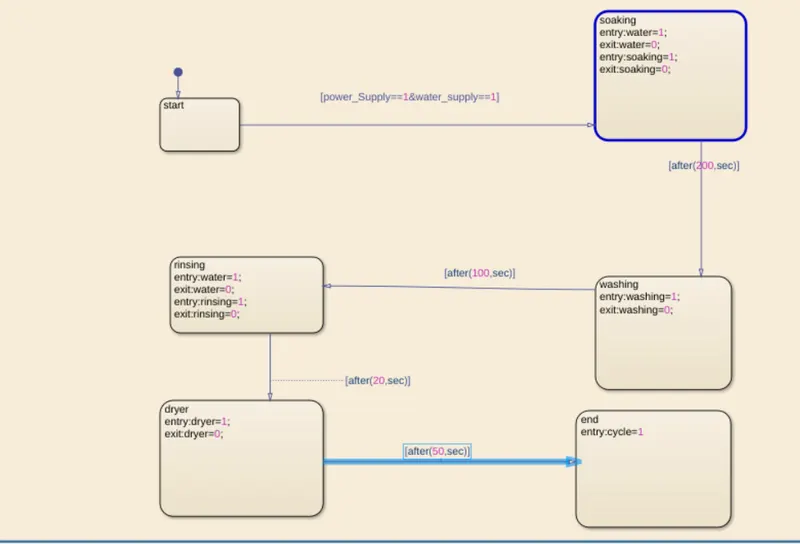
- The control logic built as per shown above
CONTROL LOGIC MODEL EXPLANATION
In the above control logic block diagram starting state is created with two transistion condition i,e,water_supply and power_supply
Soaking time = 200s
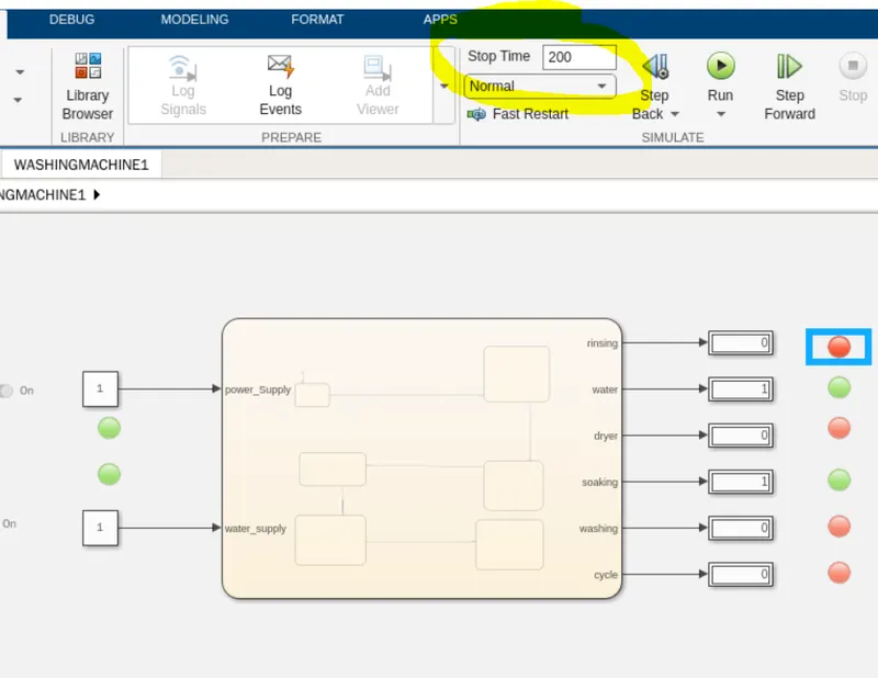
As we can see in above ,the stop time is 200sec the water and the Soaking Lamp showing green light which means as per the given condition soaking time is 200sec
Washing time = 100sec
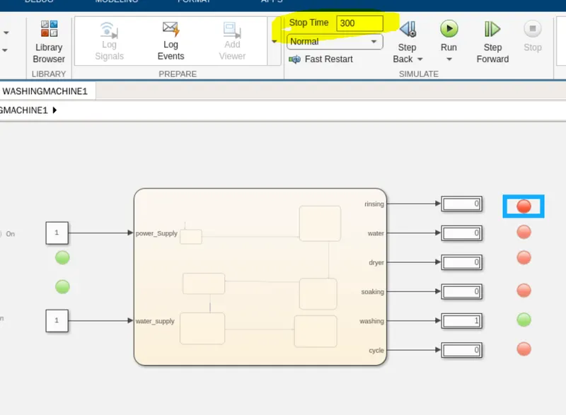
As we can see in above ,the stop time is 300sec the washing Lamp showing green light which means as per the given condition washing time should be 200+100 that is 300sec
Rinsing Time=20sec
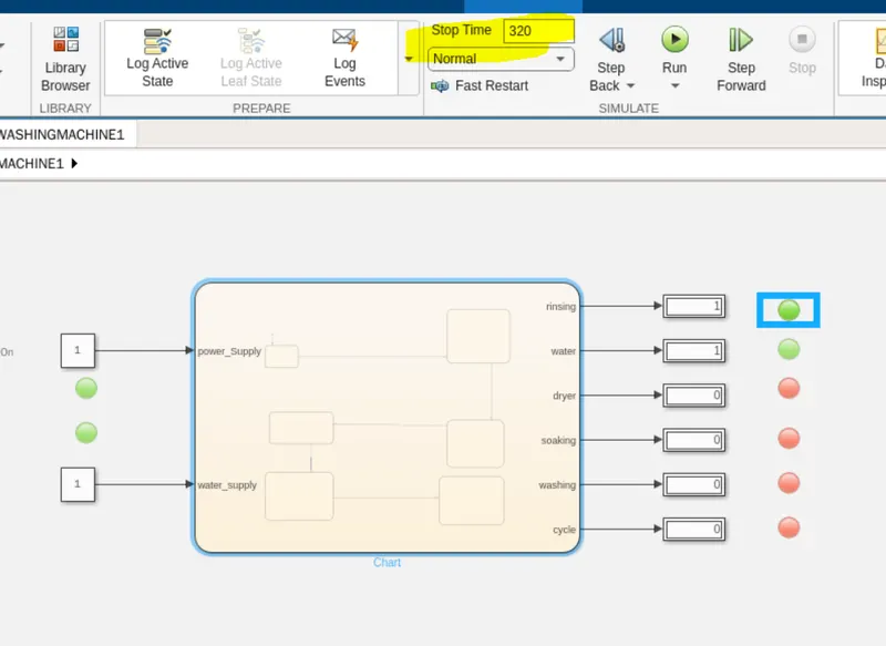
As we can see in above ,the stop time is 320sec the water and rinsing Lamp showing green light which means as per the given condition rinsing time should be 300+20 that is 320sec
Dryer time=50sec
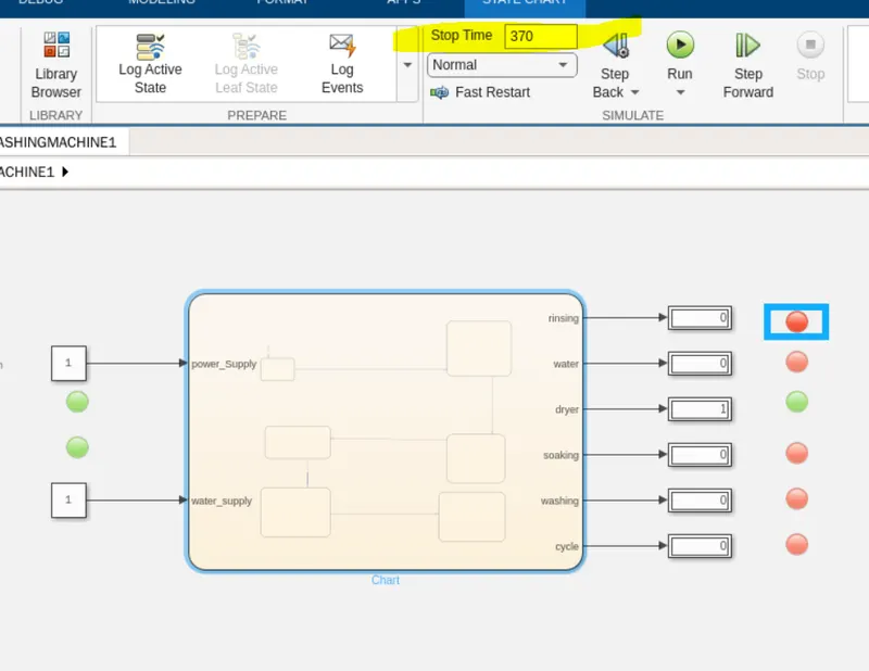
The stop time is 370 sec the dryer Lamp showing green light which means as per the given condition dryer time should be 320+50 that is 370sec
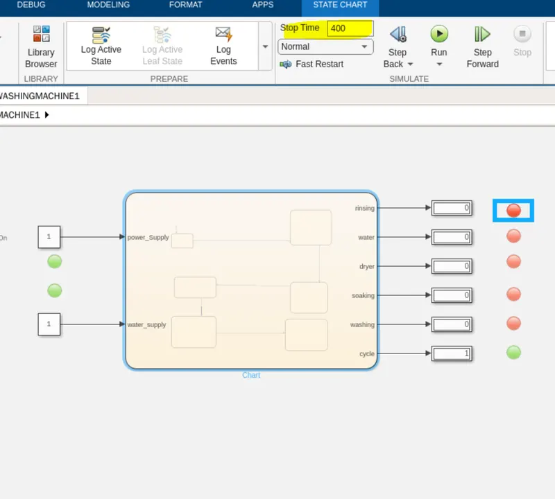
After that, all the processes have completed and turned on the finished cycle LED as shown in the above image
CONCLUSION
We can conclude that we simulate the washing machine control logic with the help of stateflow and got satisfactory results.
TASK2
2. Make a Simulink chart for the “Gear shift” logic as per below conditions:
Speed Range(kmph) Gear
0 to 15 1
16 to 25 2
26 to 40 3
41 to 60 4
Above 61 5
Give speed input while the simulation is running & display the gear number.
THEORY
Gears are wheels with teeth that slot together. When one gear is turned the other one turns as well. If the gears are of different sizes, they can be used to increase the power of a turning force. The smaller wheel turns more quickly but with less force, while the bigger one turns more slowly with more force.
- Spur Gear: The spur gear has a helix angle of 0°.
- Worm Gear: Worm gears are found in right angle gearboxes. They “turn a corner.”
- Helical Gear: This is an angle toothed gear. ...
- Bevel Gear: Bevel gears tend to have a lower ratio and run at a higher efficiency than worm gears.
WORKING MODEL
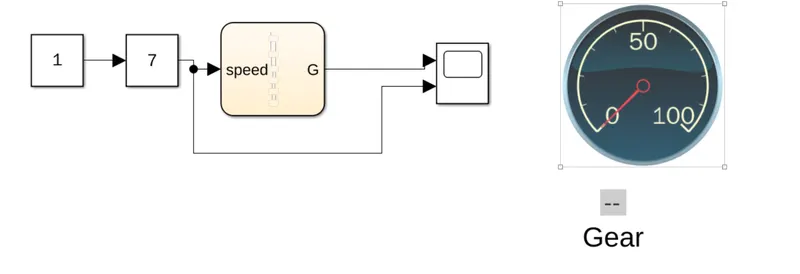
Blocks used
- Constant
- Slider Gain
- State flow chart
- Scope
- Display
- Circular Guage
WORKING OF SUBSYSTEM MODEL
- The model has a simple control logic with a simple arithmetic equation
- Here we have 5 speed range and 5 gear system
- According to the requirement we have built the control logic
- Where it checks the speed and control the gear arrangement
- Following is the gear arrangement given is stateflow logic
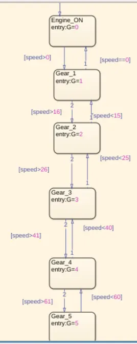
- Here we have given the input input as a Speed and output as Gear
- The stateflow logic will control the speed and as per that gear will change accordingly
- the two block dispaly and circular guage will shows the input speed and gear values
- After runnintg the simulation we can change the speed using slider gain respective Gear in display and input speed is shown in a circular guage
- Here we used Scope to record the speed input and gear output for the entire simulation
RESULT
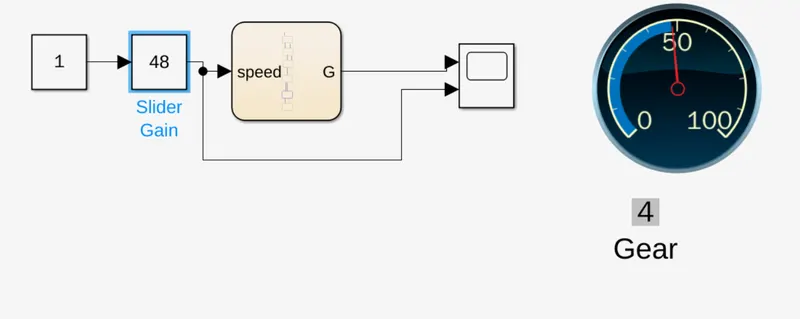
In the above figure the Speed Range is given 48(kmph), its given by using the slider gain, as per the condition speed lies between 41 to 60(kmph) then the gear should be 4
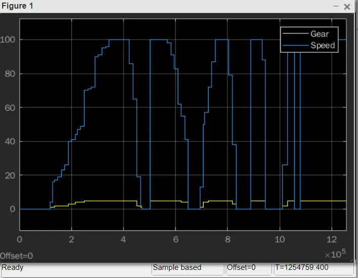
Following is the graph for the gear values according to the speed changes as per the given conditions
CONCLUSION
We can conclude that we simulation of the gear change according to the speed, control logic with the help of stateflow and got satisfactory results
```````````````````````````````````````````````````````````````````````````````````````````````````