Week-6 Challenge: EV Drivetrain
AIM:
To carry out the following study
- Which types of power converter circuits are employed in an electric and hybrid electric vehicle?
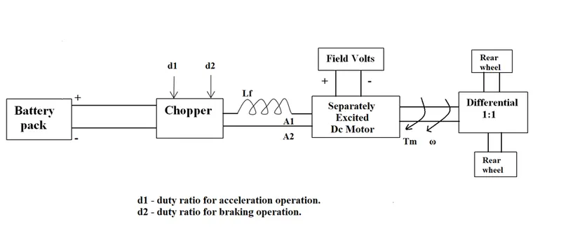
- An Electric Vehicle's powertrain with a 72V battery pack is shown in the diagram below. The duty ratio for acceleration operation is 'd1' and for the braking operation the duty ratio is 'd2'.
The other parameters of the electric vehicle are given below,
Motor and Controller Parameters:
Rated Armature voltage= 72 V
Rated armature current= 400 A
Ra= 0.5Ω, KΦ= 0.7 Volt second
Chopper Switching frequency= 400 Hz
The vehicle speed-torque characteristics are given by the below equation
What is EV steady-state speed if the duty cycle is 70%?
- Develop a mathematical model of a DC Motor for the below equation using Simulink.
ω= V/Kϕ -Ra/Kϕ^2 .T
- Refer to the blog on the below topic:
Induction Versus DC brushless motors by Wally Rippel, Tesla
Explain in brief about the author’s perspective.
Solution 1:
- Which types of power converter circuits are employed in an electric and hybrid electric vehicle?
Power converter:
- A power converter is an electrical circuit that changes the electric energy from one form into the desired form optimized for the specific load. A converter may do one or more functions and give an output that differs from the input.
- It is used to increase or decrease the magnitude of the input voltage, invert polarity, or produce several output voltages of either the same polarity with the input, different polarity, or mixed polarities such as in the computer power supply unit.
- The converter acts as the link or the transforming stage between the power source and the power supply output.
- There are several kings of converters based on the source input voltage and the output voltage and these fall into four categories namely the AC to DC converter known as the rectifier, the AC to AC cyclo converter or frequency changer, the DC to DC voltage or current converter, and the DC to AC inverter.
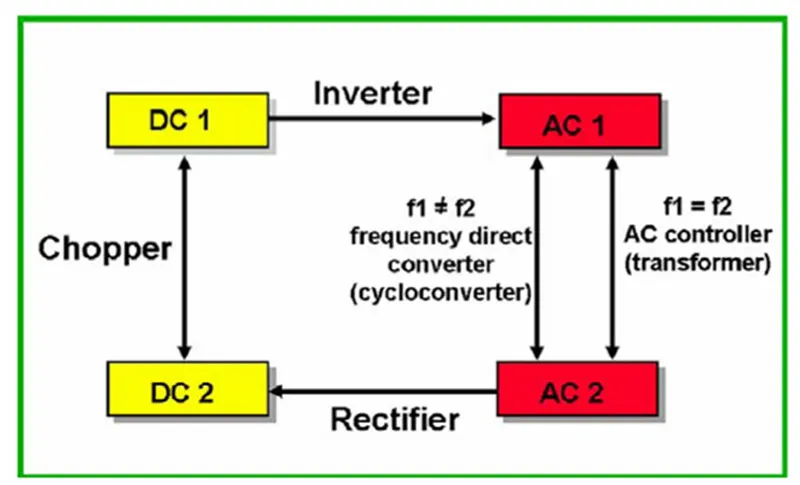
Depending on the type of function performed, power electronic converters are categorized into the following types.
AC to DC = Rectifier: It converts AC to unipolar (DC) current
DC to AC = Inverter: It converts DC to AC of desired frequency and voltage
DC to DC = Chopper: It converts constant to variable DC or variable DC to constant DC
AC to AC = Cycloconverter, Matrix converter: It converts AC of the desired frequency and/or desired voltage magnitude from a line AC supply.
DC to DC converters:
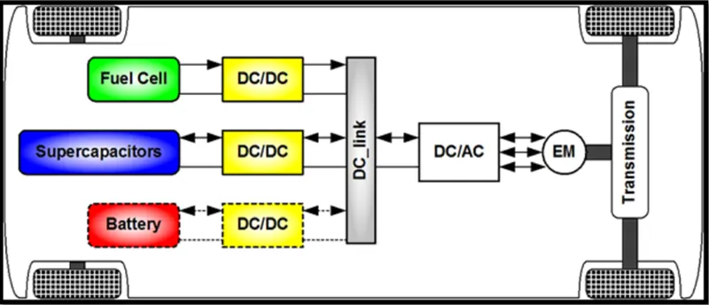
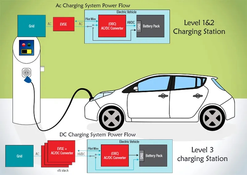
- Dc to dc converter can be used to interface the elements in the electric power train by boosting or chopping the voltage levels.
- By using dc-dc converter one can choose the voltage variation of the device and the power of each device can be controlled.
DC-AC converter:
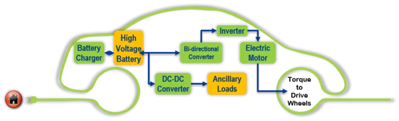
- The DC-AC converter is used to convert the dc power to the required ac power for the electrical machine. The power output from the battery pack is converted using a DC-AC converter to be used in an electric motor.
AC-DC converters:
- It converter is used to convert the ac signal to the required dc signal. It is known as a charging unit
Solution 2:
An Electric Vehicle's powertrain with a 72V battery pack is shown in the diagram below. The duty ratio for acceleration operation is 'd1' and for the braking operation the duty ratio is 'd2'.
The other parameters of the electric vehicle are given below,
Motor and Controller Parameters:
Rated Armature voltage= 72 V
Rated armature current= 400 A
Ra= 0.5Ω, KΦ= 0.7 Volt second
Chopper Switching frequency= 400 Hz
The vehicle speed-torque characteristics are given by the below equation
What is EV steady-state speed if the duty cycle is 70%?
Given:
Battery pack (Vb) = 72V
Rated Armature voltage(Va)= 72 V
Rated armature current (Ia)= 400 A
Ra= 0.5Ω
KΦ= 0.7
Chopper Switching frequency= 400 Hz
The vehicle speed-torque characteristics
equation =  …eq (1)
Solution:
Torque speed equation of DC motor ω= V/Kϕ -Ra/Kϕ^2 .T
Then,
T= v Kϕ/Ra- Kϕ^2/Ra . ω
Supply voltage to motor terminal @ 70% duty cycle is 0.7*72=50.4V
T= (50.4*0.7)/0.5 – (0.7)^2/0.5* ω
T=70.56-0.98 ω ….eq(2)
Equating eq(1) & eq(2)
70.56-0.98 ω = 24.7+0.0051 ω^2
0.0051 ω^2 + 0.98 ω – 45.86 =0 …..eq(3)
Eq(3) represent the quadratic eq of form ax2 +bx+c
Where a=0.0051 b=0.98 c=-45.86 subsitude in ω= -b±√b2−4ac/2a
ω=-0.98 ±√〖(−0.98)〗2−4(0.0051).(−45.86)/2(0.0051)
ω=-0.981.376 /0.0102
ω=-0.98+1.376/0.0102 or -0.98-1.376/0.0102
ω=38.82 or -230.98
steady speed of EV @ 70% duty cycle is 38.82 rad/s
solution 3:
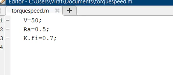
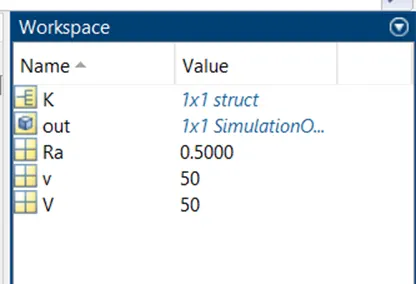
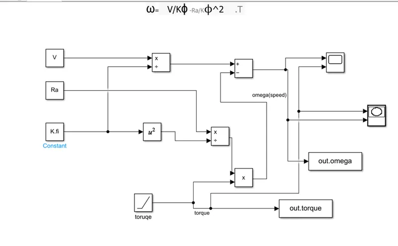
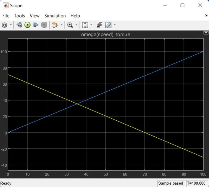
mathematical model of a DC Motor for the below equation using Simulink.
ω= V/Kϕ -Ra/Kϕ^2 .T
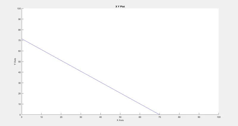
Torque-speed characteristic graph:
Solution 4:
Refer to the blog on the below topic:
Induction Versus DC brushless motors by Wally Rippel, Tesla
Explain in brief about author’s perspective
Induction Versus DC Brushless Motors
- The author says the EV vehicles development. the two types of motor to be used .theire are induction motor and brushless dc motor let's start with DC brushless drives.
- With brushless machines, the rotor includes two or more permanent magnets that generate a DC magnetic field (as seen from the vantage point of the rotor).
- In turn, this magnetic field enters the stator core (a core made up of thin, stacked laminations) and interacts with currents flowing within the windings to produce a torque interaction between the rotor and stator.
- As the rotor rotates, the magnitude and polarity of the stator currents must be continuously varied – and in just the right way - such that the torque remains constant and the conversion of electrical to mechanical energy is optimally efficient.
- The device that provides this current control is called an inverter. Without it, brushless motors are useless motors.
- Unlike the DC brushless rotor, the induction rotor has no magnets – just stacked steel laminations with buried peripheral conductors that form a “shorted structure.” Currents flowing in the stator windings produce a rotating magnetic field that enters the rotor.
- a brushless DC motor produces no starting torque when directly connected to fixed frequency utility power.
- One of the main differences is that much less rotor heat is generated with the DC brushless drive. Rotor cooling is easier and peak point efficiency is generally higher for this drive.
- The DC brushless drive can also operate at a unity power factor, whereas the best power factor for the induction drive is about 85 percent.
- This means that the peak point energy efficiency for a DC brushless drive will typically be a few percentage points higher than for an induction drive.
- induction machines have no magnets and B fields are “adjustable,” since B is proportionate to V/f (voltage to frequency). This means that at light loads the inverter can reduce voltage such that magnetic losses are reduced and efficiency is maximized. Thus, the induction machine when operated with a smart inverter has an advantage over a DC brushless machine – magnetic and conduction losses can be traded such that efficiency is optimized.
- This advantage becomes increasingly important as performance is increased. With DC brushless, as machine size grows, the magnetic losses increase proportionately and part load efficiency drops.
- With induction, as machine size grows, losses do not necessarily grow. Thus, induction drives may be the favored approach where high performance is desired; peak efficiency will be a little less than with DC brushless, but average efficiency may be better