Project
AIM:-
To study, analyze and make a detailed report on BAJA All-Terrain Vehicle(ATV) model using Simulink and compare between its different modes.
Objective:-
Prepare a technical report explaining the model properties and comments on the results.
Theory:-
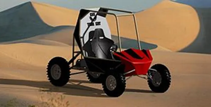
- AVT: The AVT is commonly called 4 wheeler in Australia, New Zealand, the US, and India. They are used for agriculture, because of their speed and light footprint. An all-terrain vehicle also known as a light vehicle, a quad bike, or simply a quad as defined by American national standard institute
- By the current ANSI definition, ATVs are intended for use by a single operator, although some companies have developed ATVs intended for use by the operator and one passenger. These ATVs are referred to as tandem ATVs.
- The rider sits on and operates these vehicles like a motorcycle, but the extra wheels give more stability at slower speeds. Although most are equipped with three or four wheels, six-wheel models exist and existed historically for specialized applications. Multiple-user analogs with side-by-side seating are called utility terrain vehicles (UTVs) side-by-side to distinguish the classes of vehicles. Both classes tend to have similar powertrain parts. engine sizes of ATVs currently for sale in the United States (as of 2008 products) range from 49 to 1,000 cc (3.0 to 61 cu in).
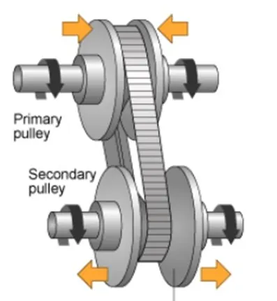
- CVT: a CVT or continuously variable transmission is an automatic, single speed and gearless transmission that can shift through an infinite number of gear ratios
- A CVT is a transmission that operates on an ingenious pulley system that automatically varies the transmission ratio, allowing an infinite variability between the highest and lowest gear with no discrete step or shift. CVTs provide more useable power, better fuel economy, and a smoother driving experience than traditional transmissions that use gearboxes with fixed numbers of gear sets
Solution:-
BAJA AVT model without dashboard:
the models consist of common blocks as follows:
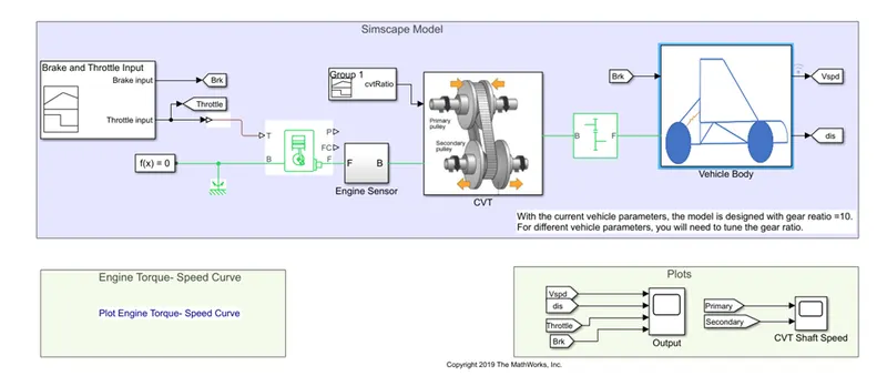
- signal builder: The Signal Builder block allows you to create interchangeable groups of piecewise linear signal sources and use them in a model.
- Goto: The Goto block passes its input to its corresponding From blocks. The input can be a real- or complex-valued signal or vector of any data type. From and Goto blocks allow you to pass a signal from one block to another without actually connecting them.
- Simulink ps converter: The Simulink-PS Converter block converts the input Simulink signal into a physical signal. Use this block to connect Simulink sources or other Simulink blocks to the inputs of a Physical Network diagram.
- Generic engine: The Generic Engine block represents a general internal combustion engine. This block is a suitable generic engine for spark-ignition and diesel. Speed-power and speed-torque parameterizations are provided. A throttle physical signal input specifies the normalized engine torque. Optional dynamic parameters include crankshaft inertia and response time lag. A physical signal port outputs the engine fuel consumption rate based on the fuel consumption model that you choose. Optional speed and redline controllers prevent engines to stall and enable cruise control.
- Solver configuration: the solver configuration block specifies the solver parameters that your model needs before you can begin the simulation.
- Mechanical rotational reference: the mechanical rotational reference block represent a reference point for all mechanical rotational ports
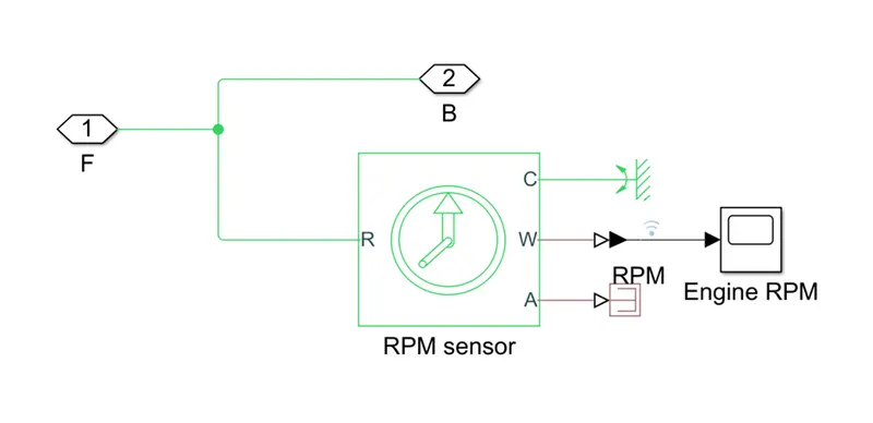
- Engine sensor: it’s a subsystem model consisting of the following simulation block
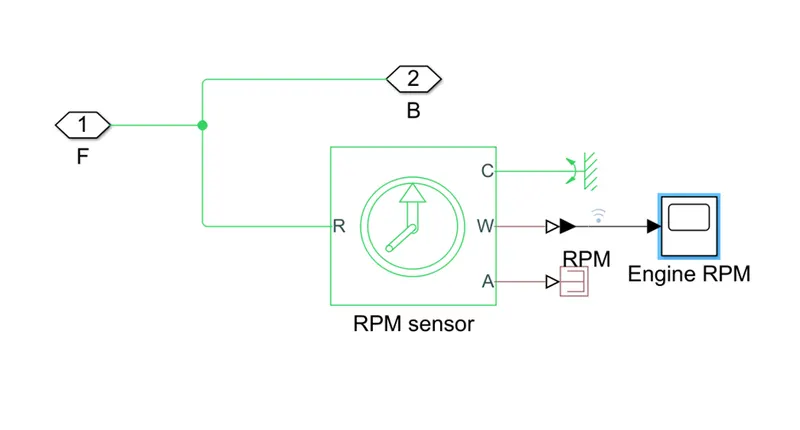
- Ideal rotational motion sensor: The Ideal Rotational Motion Sensor block represents an ideal mechanical rotational motion sensor, that is, a device that converts an across variable measured between two mechanical rotational nodes into a control signal proportional to angular velocity or angle.
- Mechanical rotational reference: the mechanical rotational reference block represent a reference point for all mechanical rotational ports
- PS-Simulink converter: converts the physical signal to a Simulink output signal
- Scope: display signal generated during simulation.
- PS terminator: use this block to terminate physical signal output.
- CVT:
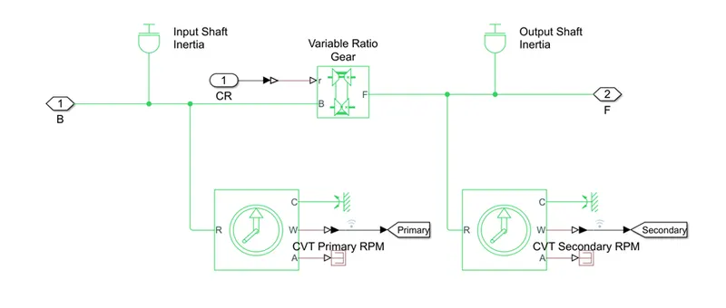
- Inertia: the block represents an ideal mechanical rotational inertia.
- Ideal rotational motion sensor: The Ideal Rotational Motion Sensor block represents an ideal mechanical rotational motion sensor, that is, a device that converts an across variable measured between two mechanical rotational nodes into a control signal proportional to angular velocity or angle.
- Mechanical rotational reference: the mechanical rotational reference block represent a reference point for all mechanical rotational ports
- PS-Simulink converter: converts the physical signal to a Simulink output signal
- goto: The Goto block passes its input to its corresponding From blocks. The input can be a real- or complex-valued signal or vector of any data type. From and Goto blocks allow you to pass a signal from one block to another without actually connecting them.
- PS-terminator: use this block to terminate physical signal output
- Variable ratio transmission: represents a variable ratio gearbox such as implemented by mechanical belt CVT, electrical or hydraulic transmission.
Simple gear: represents a fixed-ratio gear or gearbox
Vehicle body: CVT- it’s a subsystem model consisting of the following simulation block
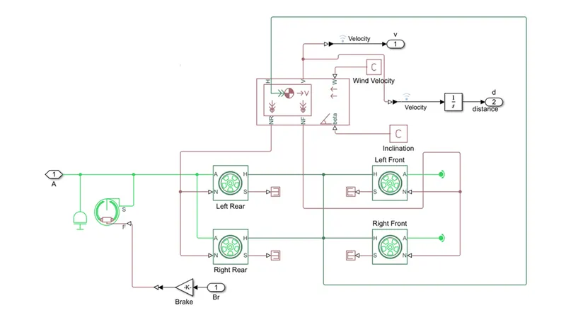
- Inertia: the block represents an ideal mechanical rotational inertia.
- Double shoe brake: represents a brake arranged as two pivoted rigid shoes symmetrically installed inside or outside a drum and operated by one actuator. The actuator force causes the shoes to exert friction torque on a shaft connected to the drum.
- Gain: element-wise gain(y=k*u) or matrix gain (y=k*u or y=u*k)
- Tire: represents the longitudinal behavior of a highway tire characterized by the tire magic formula
- PS terminator: use this block to terminate physical signal output.
- Vehicle body: represents a two axel vehicle's body in longitudinal motion. The block account axels due to acceleration and road profile.
- PS-Simulink converter: converts the physical signal to a Simulink output signal
- PS-constant: this block creates a physical signal constant
- Integrator: the integrator block outputs the value of the integral of its input signal with respect to the time
- From: The From block accepts a signal from a corresponding Goto block, then passes it as output. The data type of the output is the same as that of the input from the Goto block. From and Goto blocks allow you to pass a signal from one block to another without actually connecting them.
- Scope: display signal generated during simulation.
Inputs for the model:
Following are the variable inputs to the model.
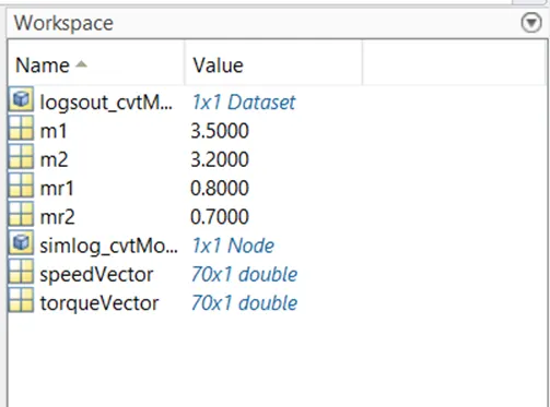
- The variable m1,m2 stands for the mass input for the inertial at input shaft and output shaft at CVT transmission system
- The variables ‘speed vector’& ’torque vector’ are the engine parameters for the generic engine, which provides us the relation between torque and rpm of the engine.
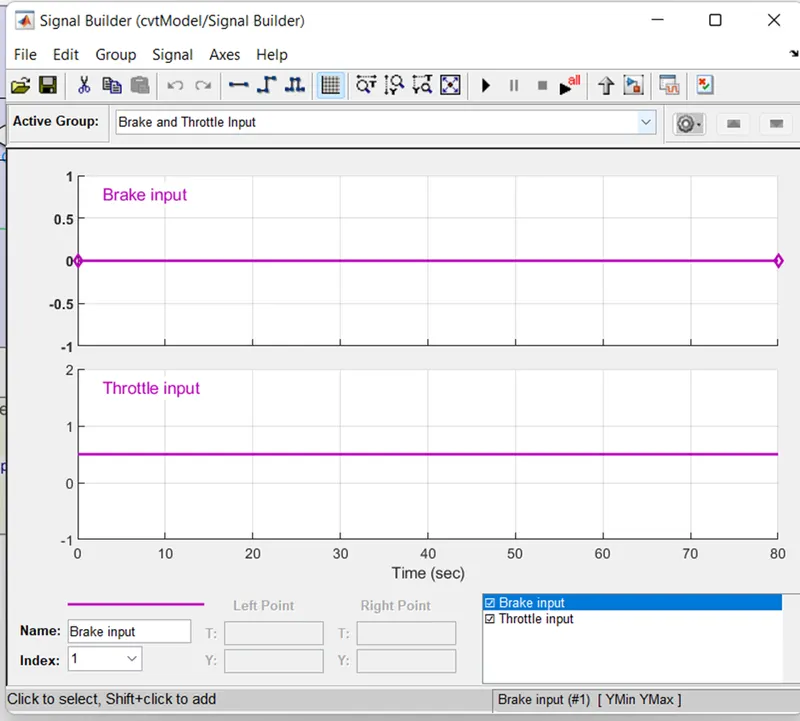
- Using signal builder block we have given throttle and brake input, and also the CVT ratio is changed with time.
Process of the model:
- The engine parameter is provided by using the variables ‘speedvector& torque vector.
- After getting the throttle input, it provides the rpm, torque, and various factors depending upon the engine parameter
- The output from the generic engine is the pass through the engine sensor block where it records the rpm of the engine during the simulation, and then forwards the CVT transmission.
- in the CVT block, it takes the two inputs one from the engine and another from the signal builder block which provides the CVT ratio
- in the CVT block, there are two ideal rotational sensor block & two inertia block each for input and output shaft respectively, and then there is the variable-ratio gear which changes it gear ratio during the simulation according to the given CVT ratio
- Now after the signal from the CVT block it passed through the simple gear block which we can say acts as a differential gearbox before passing the vehicle body.
- In the vehicles body block, it requires two inputs one from the engine which we get through the simple gear block and another is the break input
- Our model is designed on basis of a TWD vehicle, the input engine signal from the simple gear is provided to both rear wheels of the vehicle's body
- There will be rotational inertia of the shaft so it is then connected to the engine input signal before it reaches the tire
- The other input break is provided the double shoe break, but before it reaches there it passes through the gain block which can say act as an intensifier for the brake input, in short, its multiples the input force, in this scenario the gain factor is 1000
- As the brake is indirectly connected to the input power wheel, hence the output from the double shoe brake block is connected to the engine input signal before it reaches the tire
- We also get the velocity of the vehicles as in output from the vehicle body block
- As the velocity signal passes through the integrator block, it also provides the distance covered by the vehicles
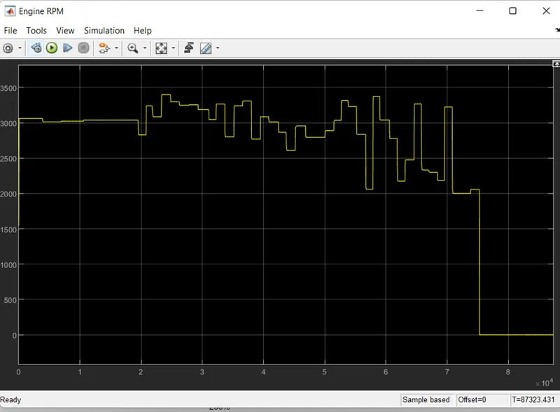
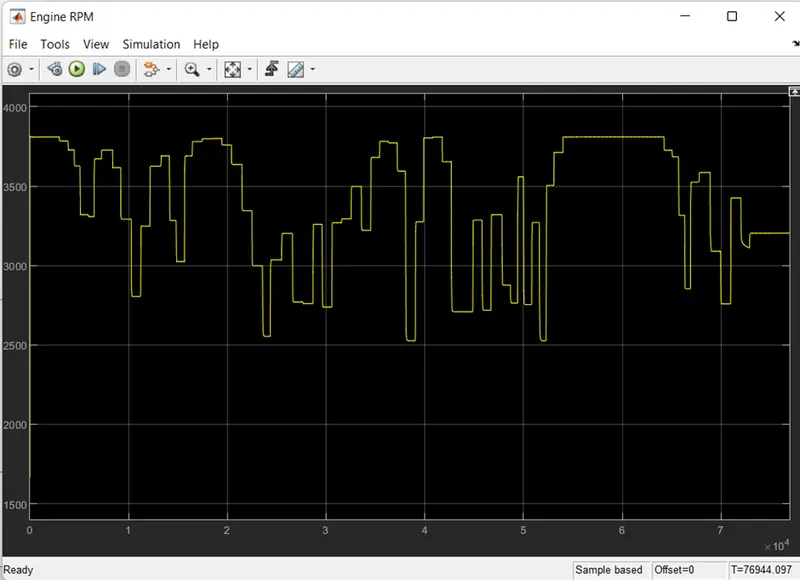
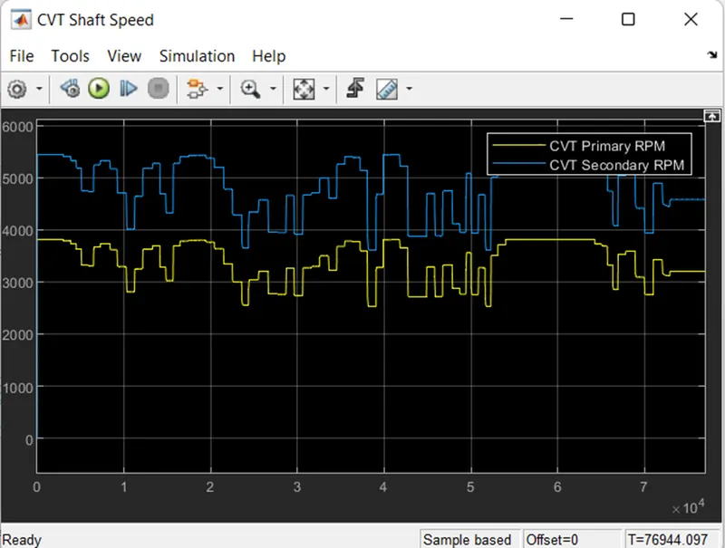
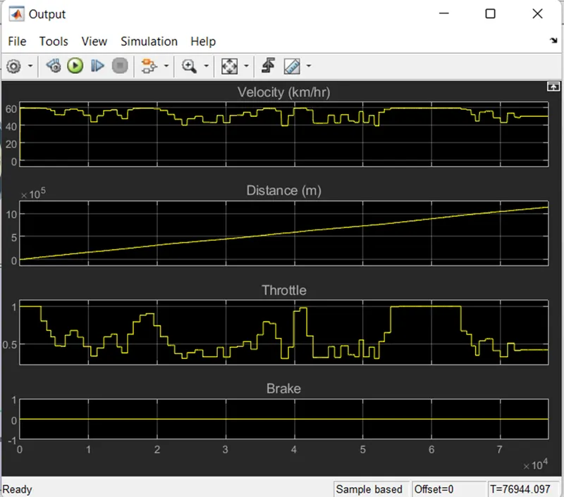
- The end of the result of the simulation in three scope data in which one has engine rpm, another has the rpm of primary and secondary shafts of CVT transmission, and the other has velocity, distance, throttle& brake values of the vehicle.
Result:
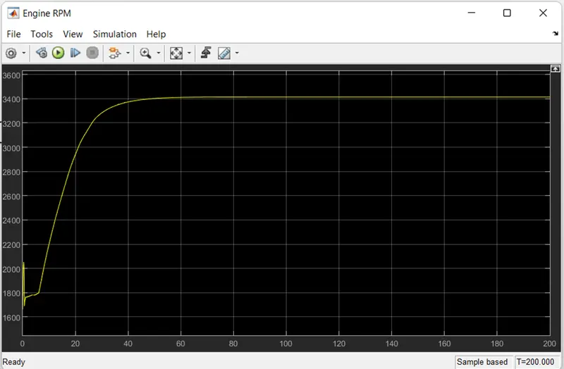
- Initial rpm of engine is defined as the 1750 rpm, then as the throttle value is constant input the rpm of engine changes accordingly
- And throttle value is constant through the complete simulation after a certain duration engine rpm become constant
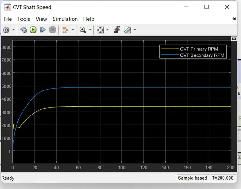
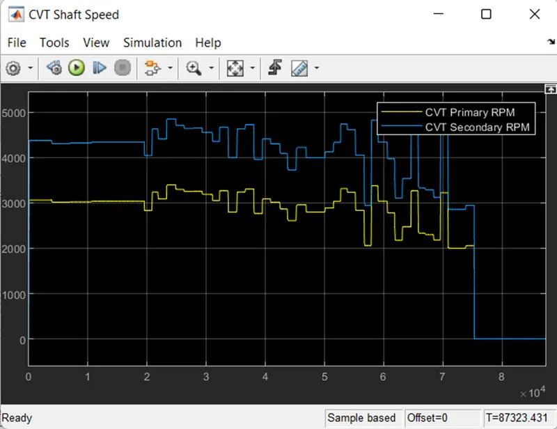
- As the primary shaft is connected to the engine it looks similar to the engine rpm but due to the inertia and one factor the primary shaft rpm will not be the same as the engine rpm and it will have some losses
- Hence primary shaft will not be the same as the engine but will have similar rpm considering some losses
- And according to the CVT ratio, the secondary shaft speed is achieved
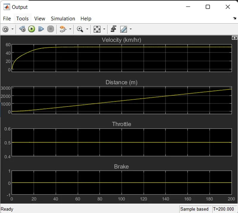
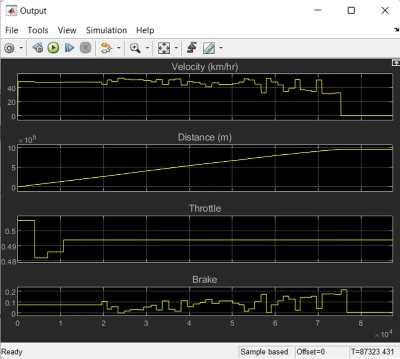
- We can verify that the throttle value & brake value are constant during the complete simulation
- Initially, the velocity of the vehicles is increased rapidly, and then after a certain point when the engine reaches its constant rpm, the velocity of the vehicles become constant
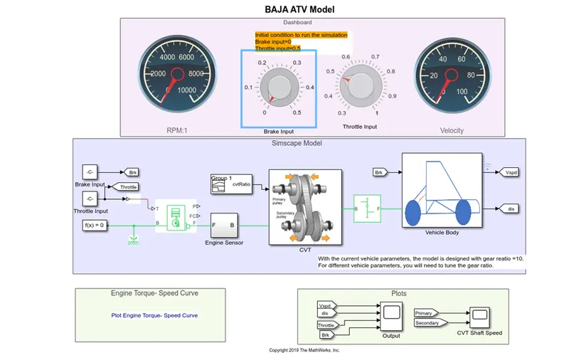
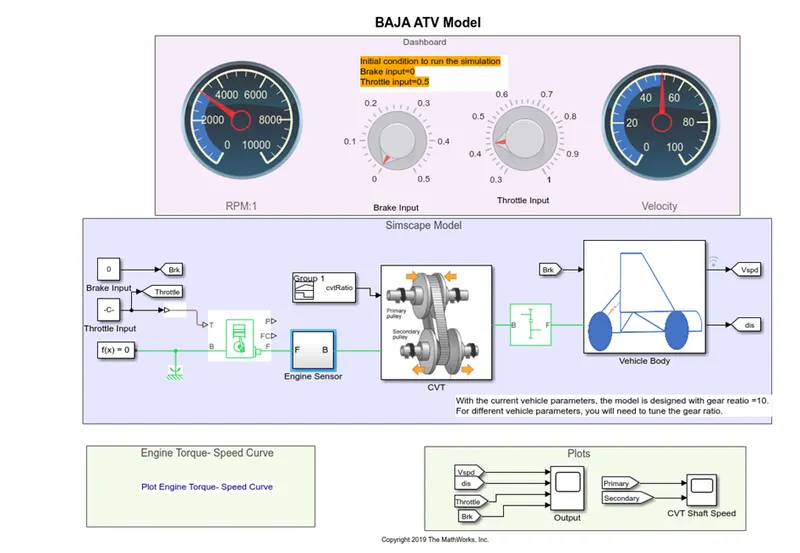
BAJA AVT Model with dashboard:
Following is the simulation model for the BAJA AVT model with dashboard
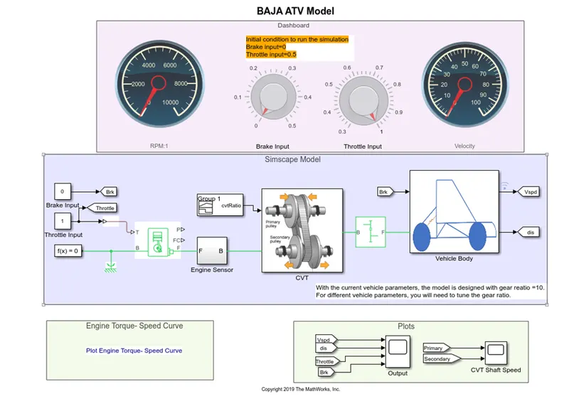
- circular gauge: display an input value on a customized gauge
- Knob: set a value to tune parameters or variables.
- Constand: output the constant specified by the constant value parameter
- Goto: The Goto block passes its input to its corresponding From blocks. The input can be a real- or complex-valued signal or vector of any data type. From and Goto blocks allow you to pass a signal from one block to another without actually connecting them.
- Simulink ps converter: The Simulink-PS Converter block converts the input Simulink signal into a physical signal. Use this block to connect Simulink sources or other Simulink blocks to the inputs of a Physical Network diagram.
- Generic engine: The Generic Engine block represents a general internal combustion engine. This block is a suitable generic engine for spark-ignition and diesel. Speed-power and speed-torque parameterizations are provided. A throttle physical signal input specifies the normalized engine torque. Optional dynamic parameters include crankshaft inertia and response time lag. A physical signal port outputs the engine fuel consumption rate based on the fuel consumption model that you choose. Optional speed and redline controllers prevent engines to stall and enable cruise control.
- Solver configuration: the solver configuration block specifies the solver parameters that your model needs before you can begin the simulation.
- Mechanical rotational reference: the mechanical rotational reference block represent a reference point for all mechanical rotational ports
- Engine sensor: it’s a subsystem model consisting of the following simulation block
- Ideal rotational motion sensor: The Ideal Rotational Motion Sensor block represents an ideal mechanical rotational motion sensor, that is, a device that converts an across variable measured between two mechanical rotational nodes into a control signal proportional to angular velocity or angle.
- Mechanical rotational reference: the mechanical rotational reference block represent a reference point for all mechanical rotational ports
- PS-Simulink converter: converts the physical signal to a Simulink output signal
- Scope: display signal generated during simulation.
- PS terminator: use this block to terminate physical signal output.
- Inertia: the block represents an ideal mechanical rotational inertia.
- Ideal rotational motion sensor: The Ideal Rotational Motion Sensor block represents an ideal mechanical rotational motion sensor, that is, a device that converts an across variable measured between two mechanical rotational nodes into a control signal proportional to angular velocity or angle.
- Mechanical rotational reference: the mechanical rotational reference block represent a reference point for all mechanical rotational ports
- PS-Simulink converter: converts the physical signal to a Simulink output signal
- goto: The Goto block passes its input to its corresponding From blocks. The input can be a real- or complex-valued signal or vector of any data type. From and Goto blocks allow you to pass a signal from one block to another without actually connecting them.
- PS-terminator: use this block to terminate physical signal output
- Variable ratio transmission: represents a variable ratio gearbox such as implemented by mechanical belt CVT, electrical or hydraulic transmission.
- Simple gear: represents a fixed-ratio gear or gearbox
- Vehicle body: CVT- it’s a subsystem model consisting of the following simulation block
- Inertia: the block represents an ideal mechanical rotational inertia.
- Double shoe brake: represents a brake arranged as two pivoted rigid shoes symmetrically installed inside or outside a drum and operated by one actuator. The actuator force causes the shoes to exert friction torque on a shaft connected to the drum.
- Gain: element-wise gain(y=k*u) or matrix gain (y=k*u or y=u*k)
- Tire: represents the longitudinal behavior of a highway tire characterized by the tire magic formula
- PS terminator: use this block to terminate physical signal output.
- Vehicle body: represents a two axel vehicle's body in longitudinal motion. The block account axels due to acceleration and road profile.
- PS-Simulink converter: converts the physical signal to a Simulink output signal
- PS-constant: this block creates a physical signal constant
- Integrator: the integrator block outputs the value of the integral of its input signal with respect to the time
- From: The From block accepts a signal from a corresponding Goto block, then passes it as output. The data type of the output is the same as that of the input from the Goto block. From and Goto blocks allow you to pass a signal from one block to another without actually connecting them.
- Scope: display signal generated during simulation.
Input for the model:
Following are the variables input to the model.
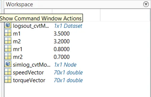
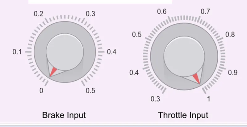
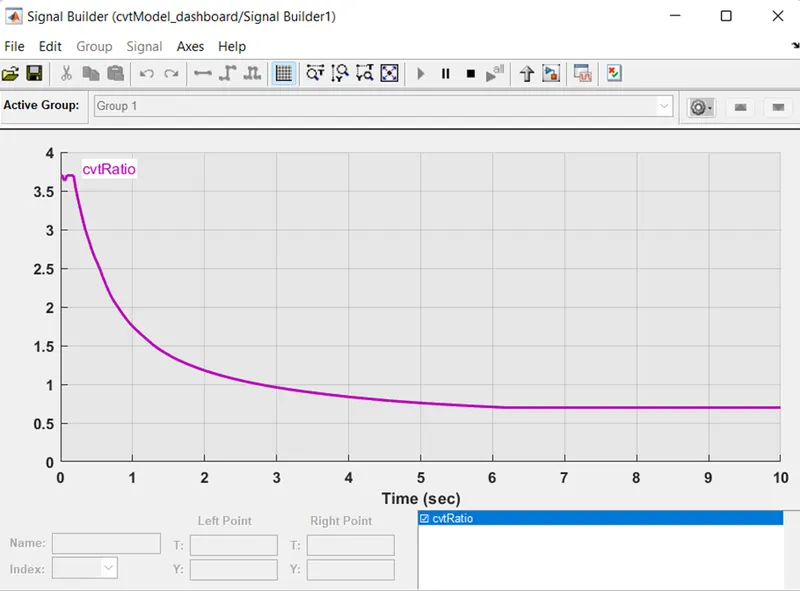
The variable m1,m2 stands for the mass input for the inertial at input shaft and output shaft at CVT transmission system. The variables ‘speed vector’& ’torque vector’ are the engine parameters for the generic engine, which provides us the relation between torque and rpm of the engine. Using the knob block where we provide the throttle and brake input while the simulation is running, its limits are provided on the knob. Using signal builder block we have given throttle and brake input, and also the CVT ratio is changed with time.
Process of the model:
- the initial condition of the engine block is already set according to the engine parameters we have and then according to the throttle input engine change its parameter of speed, torque, and other.
- For this model, the engine parameter is provided by using the variable speed vector & torque vector. the throttle and brake input is provided by using the user interface knob block which allows the user to change the throttle and brake input while the simulation is running.
- The output from the generic engine is the pass through the engine sensor block where it records the rpm of the engine during the simulation, and then forwards the CVT transmission.
- in the CVT block, it takes the two inputs one from the engine and another from the signal builder block which provides the CVT ratio
- in the CVT block, there are two ideal rotational sensor blocks & two inertia blocks each for input and output shaft respectively, and then there is the variable-ratio gear which changes its gear ratio during the simulation according to the given CVT ratio
- Now after the signal from the CVT block it passed through the simple gear block which we can say acts as a differential gearbox before passing the vehicle body.
- In the vehicles body block, it requires two inputs one from the engine which we get through the simple gear block and another is the break input
- Our model is designed on basis of a TWD vehicle, the input engine signal from the simple gear is provided to both rear wheels of the vehicle's body.
- There will be rotational inertia of the shaft so it is then connected to the engine input signal before it reaches the tire
- The other input break is provided the double shoe break, but before it reaches there it passes through the gain block which can say act as an intensifier for the brake input, in short, its multiples the input force, in this scenario the gain factor is 1000
- As the brake is indirectly connected to the input power wheel, hence the output from the double shoe brake block is connected to the engine input signal before it reaches the tire
- We also get the velocity of the vehicles as in output from the vehicle body block
- As the velocity signal passes through the integrator block, it also provides the distance covered by the vehicles
- The end of the result of the simulation in three scope data in which one has engine rpm, another has the rpm of primary and secondary shafts of CVT transmission, and the other has velocity, distance, throttle& brake values of the vehicle.
Result:
Case1:break=0,throttle=0.5:-
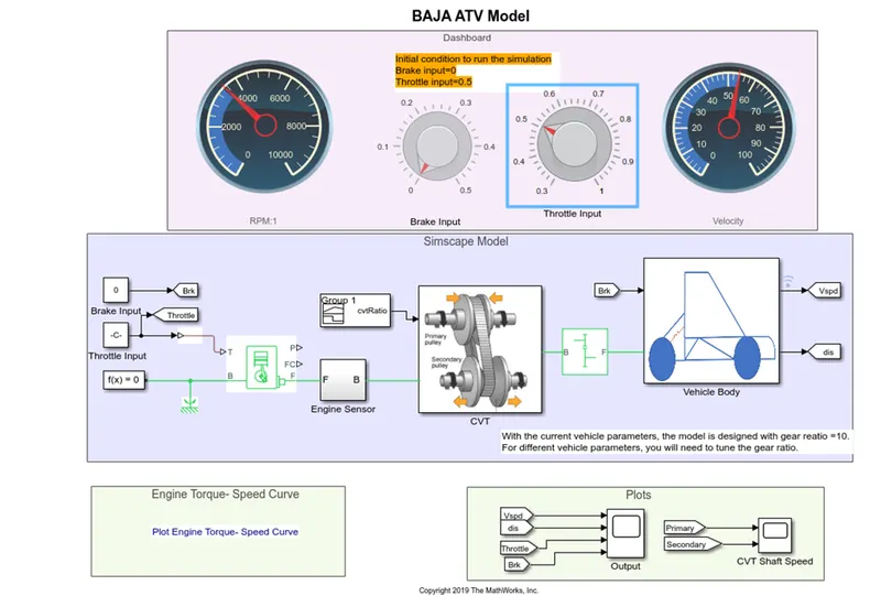
Initially brake set to 0 and throttle value set to 0.5 the output to display the scope
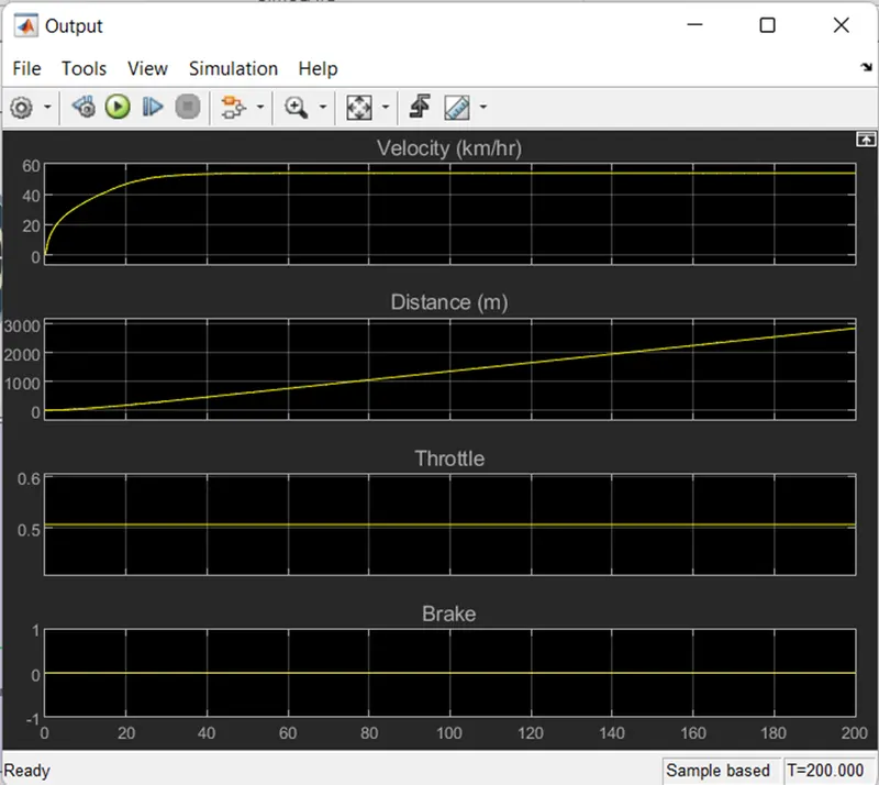
- We can verify that the throttle value & brake value are constant during the complete simulation
- Initially, the velocity of the vehicles is increased rapidly, and then after a certain point when the engine reaches its constant rpm, the velocity of the vehicles become constant
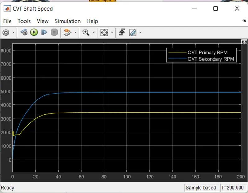
- As the primary shaft is connected to the engine it looks similar to the engine rpm but due to the inertia and one factor the primary shaft rpm will not be the same as the engine rpm and it will have some losses
- Hence primary shaft will not be the same as the engine but will have similar rpm considering some losses
- And according to the CVT ratio, the secondary shaft speed is achieved
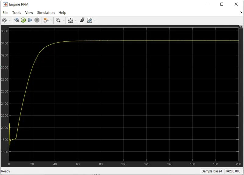
- Initial rpm of engine is defined as the 1750 rpm, then as the throttle value is constant input the rpm of engine changes accordingly
- And throttle value is constant through the complete simulation after a certain duration engine rpm become constant
Case2:brake=varing,throttle=0.5:-
Case3:break=0,throttele=varing:-
Conclusion:
We can understand easily how the vehicle may perform under the provided conditions. we can calculate the time required to attain a certain amount of speed or to stop the vehicle completely. We can also calculate what will be the maximum speed vehicle can achieve. we are also able to observe the performance of the braking system and throttle system. This model helps us to verify the performance of the vehicles under the constructed brake system and throttle system.
Download the model from the given link:
https://www.mathworks.com/matlabcentral/fileexchange/70576-baja-all-terrain-vehicle-atv-model