Week-6 Challenge: EV Drivetrain
Problem 01:
Aim:
To analyze power converter circuits are employed in an electric and hybrid electric vehicles.
Electric Power Converters:
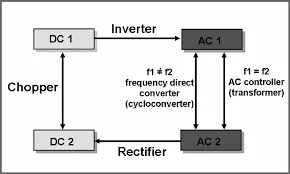
Power electronic technology deals with processing and controlling the flow of electrical energy in order to supply voltages and currents in a form that is optimally suited for the end users’ requirements. A power electronic converter uses power electronic converters such as SCRs, TRIACs, IGBTs, etc. to control and convert the electric power. The main aim of the converter is to produce conditioning power with respect to a certain application. Power electronic converters perform various basic power conversion functions. This converter is a single power conversion stage that can perform any of the functions in AC and DC power conversion systems.
AC to DC Converters:
An AC to DC converter is also called a rectifier, which converts AC supply from main lines to DC supply for the load. The rectifier converts the low voltage AC supply into a DC supply. It comprises a diode and/or thyristors based on the type of rectifier. The output of the rectifier is of pulsed DC and hence it is filtered using a filter circuit, which is usually made with a capacitor or a choke. The control block controls the firing angle of thyristors in the case of phase-controlled rectifiers. Since the diode is not a controllable device, a control block is not needed in the case of diode rectifiers.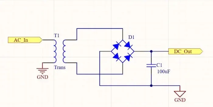
DC to AC Converters:
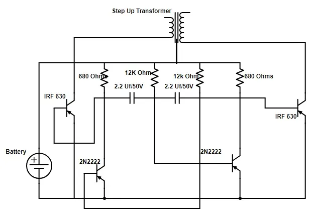
DC to AC converters is mainly designed for changing a DC power supply to an AC power supply. Here, DC power supply is comparatively stable as well as a positive voltage source whereas AC oscillates at approximately a 0V base stage, typically in a sinusoidal or square mode. The common inverter technology used in electronics is to convert a voltage source from a battery into an AC signal. Generally, they operate with 12 volts and are commonly used in applications like automotive, lead-acid technology, photovoltaic cell, etc.
AC to AC Converters:
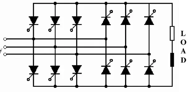
For speed control of induction motors, AC to AC converters (Cycloconverters) is used majorly. For obtaining a desired AC power supply from the actual power supply, we need some converters called AC to AC converters.
Cycloconverters consist of two limbs namely a Positive limb also called a positive converter and a negative limb also called a negative converter. The Positivelimb operates during the positive half cycle and the negative limb operates during the negative half cycle.
DC to DC Converters:
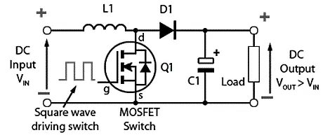
The DC-to-DC converters convert one level of DC voltage to another level. The operating voltage of different electronic devices such as ICs, and MOSFET can vary over a wide range, making it necessary to provide a voltage for each device. A Buck Converter outputs a lower voltage than the original voltage, while a Boost Converter supplies a higher voltage. With the application of DC-to-DC Converters, the circuit’s efficiency, ripple, and load-transient response can be changed. Optimal external parts and components are generally dependent on operating conditions such as input and output specifications. So, while designing the products, the standard circuits must be varied or changed according to and as per the need to their individual specification requirements. Designing a circuit that satisfies the specification and all the requirements needs a great deal of expertise and experience in that field.
Problem 02:
Aim:
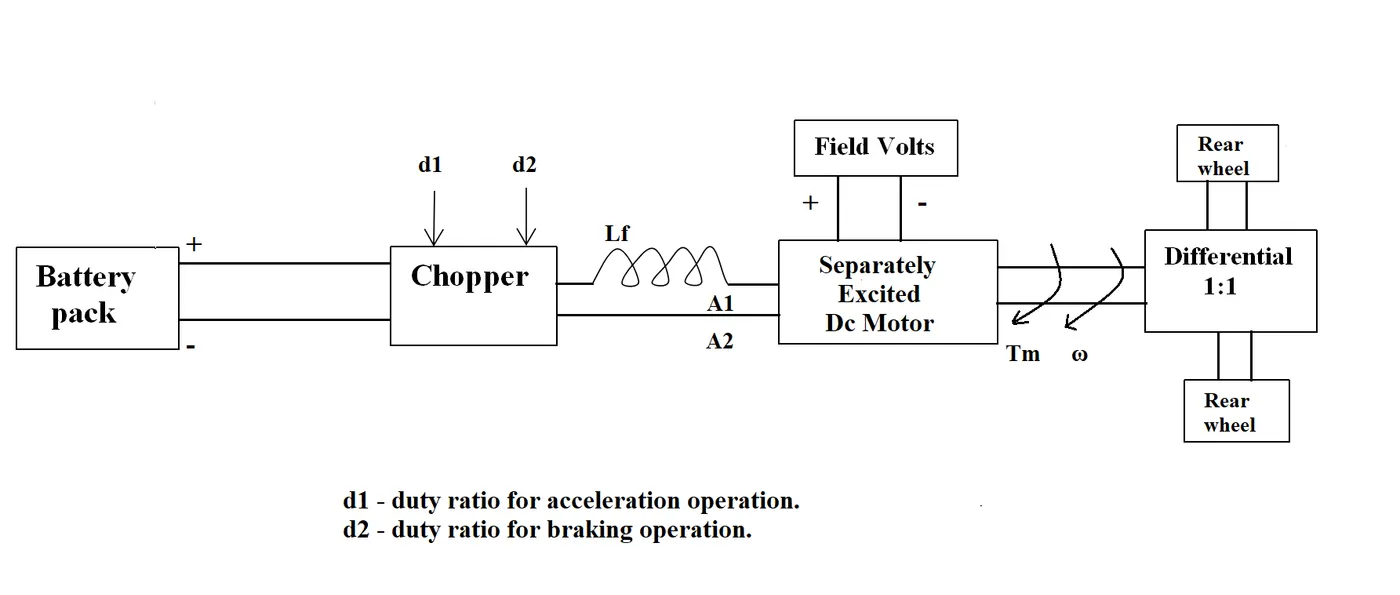
To calculate the EV steady-state speed if the duty cycle is 70%.
Given:
Rated Armature voltage= 72 V
Rated armature current= 400 A
Ra= 0.5Ω, KΦ= 0.7 Volt second
Chopper Switching frequency= 400 Hz
Solution:
Duty cycle is 70% = 0.7
voltage = 0.7 x 72 = 50.4
Tv = 24.7 + (0.0051) ω^2..................................eq 1
T = vkϕ/Ra - ((kϕ)^2)/Ra) ω
T = 50.4 x 0.7/0.5 ((0.7)^2/0.5) ω
T = 70.56 - 0.98 ω............................................eq 2
Solving eq 1 and eq 2:
Comparing Torque Parameters of the equation,
24.7 + (0.0051) ω^2 = 70.56 - (0.98) ω
0.0051 ω^2 + 0.98 ω -45.86 =0
By solving this by quadratic equation,
ω = 38.915 Rad/sec and ω= -231.072 Rad/sec
Consider duty cycle is 70%,
= 38.915 Rad/Sec
Problem 03:
Aim:
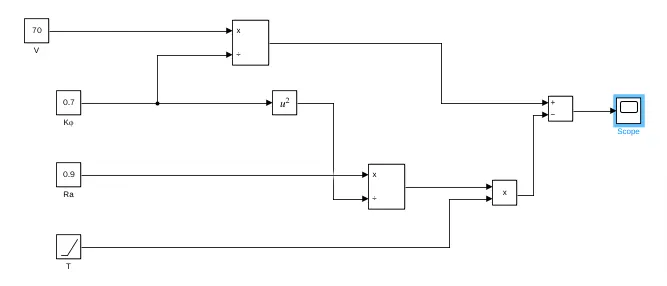
To develop a mathematical model of a DC Motor for the below equation using Simulink.
ω = V/Kϕ -Ra/Kϕ^2 x T
Given:
ω = V/Kϕ -Ra/Kϕ^2 x T
Simulink Model:
Blocks used: Constant, Ramp, Adder, Product, and Scope.
Output:
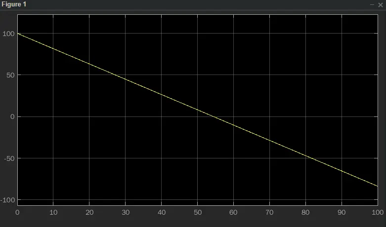
The torque-speed is shown in the output below,
Problem 04:
Aim:
To refer to and analyze the blog given and give a brief in the author’s perspective.
Explanation:
In that odious world of gas-powered vehicles, engines are not all alike. There are flat-heads, Hemis, straight, opposed, and V configurations. And on and on. One would have thought that, years ago, someone would have figured out which was best. That would have ended all the choices and thereafter only the one best engine type would be in production. Not so. There is no one best engine type, rather there are different types of engines to suit personal requirements, such as price and performance. This is also true for electric vehicle drives.
- Brushless or Induction?
Back in the 1990s all of the electric vehicles except one were powered by DC brushless drives. Today, all the hybrids are powered by DC brushless drives, with no exceptions. Both DC brushless and induction drives use motors having similar stators. Both drives use 3-phase modulating inverters. The only differences are the rotors and the inverter controls. And with digital controllers, the only control differences are with control code. (DC brushless drives require an absolute position sensor, while induction drives require only a speed sensor; these differences are relatively small. - In an ideal brushless drive, the strength of the magnetic field produced by the permanent magnets would be adjustable. When maximum torque is required, especially at low speeds, the magnetic field strength (B) should be maximum – so that inverter and motor currents are maintained at their lowest possible values. This minimizes the I² R (current² resistance) losses and thereby optimizes efficiency.
- Induction machines are more difficult to control. The control laws are more complex and difficult to understand. Achieving stability over the entire torque-speed range and over temperature is more difficult with induction than with DC brushless. This means added development costs, but likely little or no recurring costs.
Conclusion:
In author’s conclusion is that DC brushless drives will likely continue to dominate in the hybrid and coming plug-in hybrid markets, and that induction drives will likely maintain dominance for the high-performance pure electrics. The question is what will happen as hybrids become more electrically intensive and as their performance levels increase? The fact that so much of the hardware is common for both drives could mean that we will see induction and DC brushless live and work side by side during the coming golden era of hybrid and electric vehicles.