Week-6 Challenge: EV Drivetrain
OBJECTIVE:
- Which types of power converter circuits are employed in electric and hybrid electric vehicle?
- An Electric Vehicle's powertrain with 72V battery pack in shown in the diagram below. The duty ratio for acceleration operation is 'd1' and for the braking operation the duty ratio is 'd2'.
The other parameters of the electric vehicle is given below,
Motor and Controller Parameters:
Rated Armature voltage= 72 V
Rated armature current= 400 A
Ra= 0.5Ω, KΦ= 0.7 Volt second
Chopper Switching frequency= 400 Hz
The vehicle speed-torque characteristics are given by the below equation
What is EV steady state speed if duty cycle is 70%?
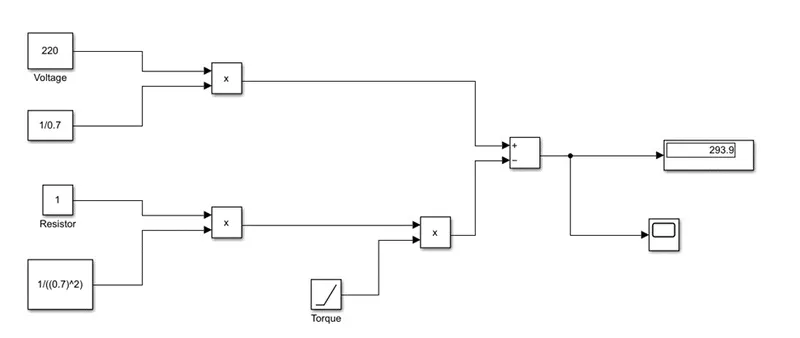
- Develop a mathematical model of a DC Motor for the below equation using Simulink.
ω= V/Kϕ -Ra/Kϕ^2 .T
ANSWERS:
PART1:
A power converter is an electrical circuit that changes the electric energy from one form into the desired form optimised for the specific load. A converter may do one or more functions and give an output that differs from the input.
The power electronic converter can be classified into six types
- Diode Rectifier
- AC to DC Converter (Controlled Rectifier)
- DC to DC Converter (DC Chopper)
- AC to AC Converter (AC Voltage regulator)
- DC to AC Converter (Inverter)
- Static Switches
In EVs, the Fuel Cell stack, Battery Bank and Super Capacitors (SCs) bank are usually used as clean energy sources. In order to design highly efficient converters for the EVs power system, Advanced DC/DC, AC/DC and DC/AC converters are required to adapt the output voltage and current levels with high power quality.
DC to DC Converter (DC Chopper)
The different configurations of EV power supply show that at least one DC/DC converter is necessary to interface the FC, the Battery or the Supercapacitors module to the DC-link. In electric engineering, a DC to DC converter is a category of power converters and it is an electric circuit which converts a source of direct current (DC) from one voltage level to another, by storing the input energy temporarily and then releasing that energy to the output at a different voltage. The storage may be in either magnetic field storage components (inductors, transformers) or electric field storage components (capacitors). DC/DC converters can be designed to transfer power in only one direction, from the input to the output. However, almost all DC/DC converter topologies can be made bi-directional. A bi-directional converter can move power in either direction, which is useful in applications requiring regenerative braking. The amount of power flow between the input and the output can be controlled by adjusting the duty cycle (ratio of on/off time of the switch). Usually, this is done to control the output voltage, the input current, the output current, or to maintain a constant power. Transformer based converters may provide isolation between the input and the output. The main drawbacks of switching converters include complexity, electronic noise and high cost for some topologies.
AC to DC Converter (Controlled Rectifier)
It’s called the “onboard charger” though it really is a converter. It converts power from AC to DC and then feeds it into the cars battery. This is the most common charging method for electric vehicles today and most chargers use AC power.
DC to AC Converter (Inverter)
- The DC to AC converter is required to convert the DC power to a suitable AC power for electrical machine. The power output from the battery pack (DC Current) is converted using inverter to get the desired AC current. Inverters do the opposite of “converters” which were originally large electromechanical devices converting AC to DC. The input voltage, output voltage and frequency, and overall power handling depend on the design of the specific device or circuitry. The inverter does not produce any power; the power is provided by the DC source.
For electric vehicles (EVS), a hybrid clamped inverter can be used to drive the traction motor from a set of batteries or fuel cells. Multilevel inverter is an alternative structure to the conventional power converter that have been accepted and used in many applications such as motor drives and static power conditioning systems.
PART2:
As the torque formula is given, we need to find the speed in radian per second. Use the other expression available which is given below:
T = (V*k/R) – ( K^2*w/R)
T = Torque
V = Armature Voltage
R = Resistance
w = speed rad/sec
Compare the two equations:
24.7 + 0.0051*w^2 = ((v*k)/R) – ((k^2)*w/R)
24.7 + 0.0051*w^2 = (72*0.7*0.7)/0.5 – (0.7^2/0.5)*w = 24.7 + 0.0051*w^2
70.56-0.98*w = 0.7 + 0.0051*w^2
w^2 + 192.15*w – 8992.15 = 0
Use the below formula to find the roots
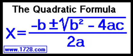
As the speed value cannot be negative,
w = 38.95 rad/sec
PART4:
Brief explanation about authors perspective:
- In the blog of Induction and DC brushless motor, the author has mentioned about positive and negative side of both the induction and DC motor. The construction of both the machines have been explained.
- In case of DC brushless motor, permanent magnets are used which produces a rotating magnetic field. This magnetic field when induces a current in the conductor , this current results in force generation in the rotor and this results in rotation of the rotor.
- Whereas in the case of Induction motor, the current is supplied to the stator which results in the generation of emf, when this emf comes in contact with the rotor which is generally a squirrel cage type, results in current induced in the rotor. Unlike the DC motor, the rotor consists of conductor plates and placed in a cage like structure. This also consists of bars around them in which current get induced and the rotor starts rotating.
- One of the main differences is that much less rotor heat is generated with the DC brushless drive. Rotor cooling is easier and peak point efficiency is generally higher for this drive. The DC brushless drive can also operate at unity power factor, whereas the best power factor for the induction drive is about 85 percent.
- In an ideal brushless drive, the strength of the magnetic field produced by the permanent magnets would be adjustable. When maximum torque is required, especially at low speeds, the magnetic field strength (B) should be maximum – so that inverter and motor currents are maintained at their lowest possible values. This minimizes the I²R (current² resistance) losses and thereby optimizes efficiency. Likewise, when torque levels are low, the B field should be reduced such that eddy and hysteresis losses due to B are also reduced. Ideally, B should be adjusted such that the sum of the eddy, hysteresis, and I² losses is minimized. Unfortunately, there is no easy way of changing B with permanent magnets.
- as machine size grows, the magnetic losses increase proportionately and part load efficiency drops. With induction, as machine size grows, losses do not necessarily grow. Thus, induction drives may be the favored approach where high-performance is desired; peak efficiency will be a little less than with DC brushless, but average efficiency may actually be better.
- Induction machines are more difficult to control. The control laws are more complex and difficult to understand. Achieving stability over the entire torque-speed range and over temperature is more difficult with induction than with DC brushless. This means added development costs, but likely little or no recurring costs.
- To conclude is that DC brushless drives will likely continue to dominate in the hybrid and coming plug-in hybrid markets, and that induction drives will likely maintain dominance for the high-performance pure electrics. The question is what will happen as hybrids become more electrically intensive and as their performance levels increase? The fact that so much of the hardware is common for both drives could mean that we will see induction and DC brushless live and work side by side during the coming golden era of hybrid and electric vehicles.
PART3:
Given the equation:
ω= (V/Kϕ) –(Ra/Kϕ^2) .T
Model for the above equation:
ω= (V/Kϕ) – (Ra/Kϕ^2) .T
RESULT:
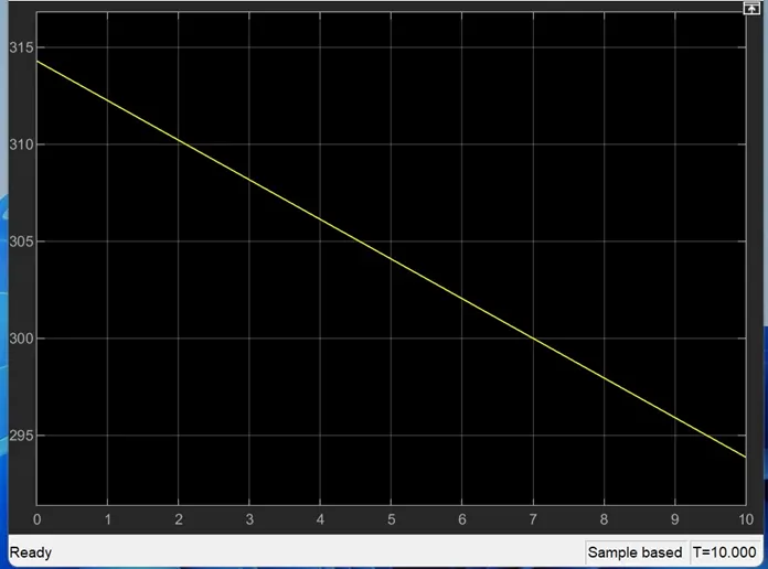
OBSERVATIONS AND RESULT:
The results were obtained as per the questions given and the results are satisfactory.