Week - 4
AIM:
To implement control logic of a washing machine and Gear shift mechanism using Stateflow.
OBJECTIVE:
- Implement control logic of a “washing machine” using Stateflow as per given sequence:
- If the power supply is available, the system gets activated
- If the Water supply is not available, stop the process & indicate through LED
- Soaking time should be 200s followed by Washing time of 100s.
- Then rinsing happens for next 20s & dryer runs for 50s.
After all the processes have completed turn on the finished LED.
- Make a Simulink chart for the “Gear shift” logic as per below conditions:
Speed Range(kmph) Gear
0 to 15 1
16 to 25 2
26 to 40 3
41 to 60 4
Above 61 5
Give speed input while the simulation is running & display the gear number.
ANSWERS:
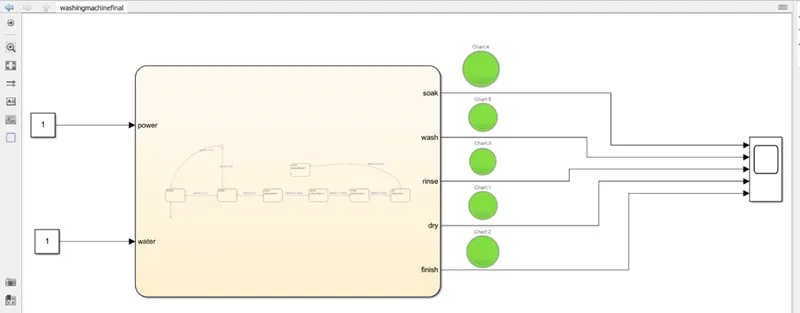
- MODEL DIAGRAM:
STATEFLOW:
MODEL EXPLANATION:
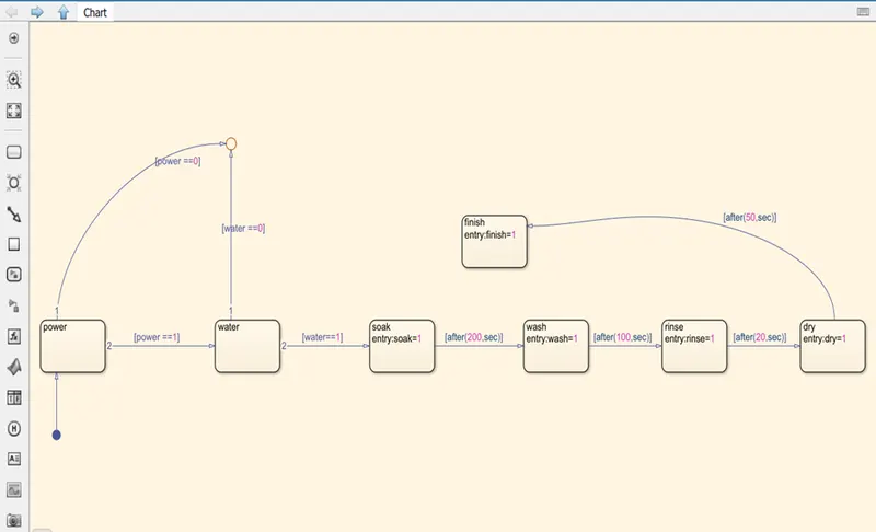
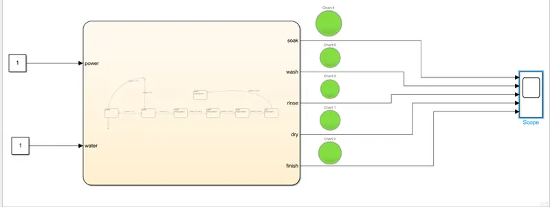
- Create a chart block for defining the stateflow as per the given conditions.
- Circular junction is to terminate the signal flow and return a null value.
- If power is OFF i.e. 0, the process is terminated or if the power is ON, the process is carried forward.
- Similarly if the Water Supply is OFF i.e. 0, the process is terminated or if the water supply is ON , the process is carried forward.
- After this, Soak block gets activated and soaking action takes place.
- After 200 seconds of soaking , wash block gets activated and washing action takes place.
- After 100 seconds of washing, rinse block gets activated and rinsing action takes place.
- After 20sec of rinsing, Dry block gets activated and drying action takes place.
- After 50sec of dry, Finish block gets activated. Finish is to terminate the signal flow and exits the chart.
- Define power and water as inputs whereas soak, wash, rinse, dry, finish as outputs.
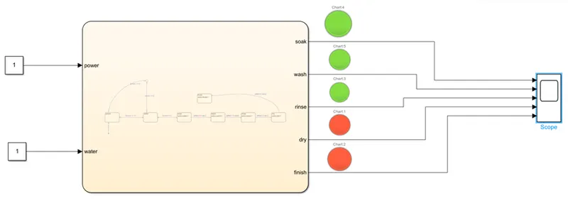
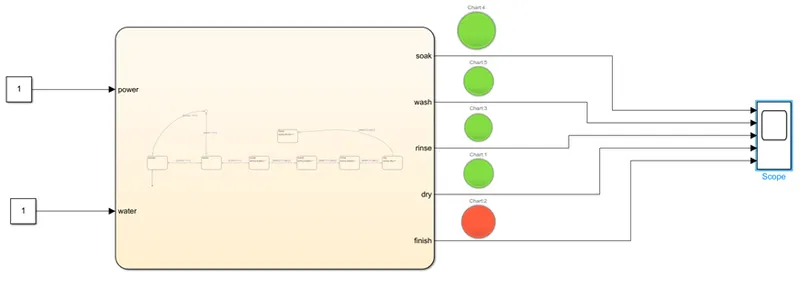
- Connect the chart block with constant blocks for power and water inputs. Attach lamps to observe the ON/OFF condition.
- A common SCOPE block is connected to observe the graphical representation of the output results of various situations.
MODEL OUTPUT:
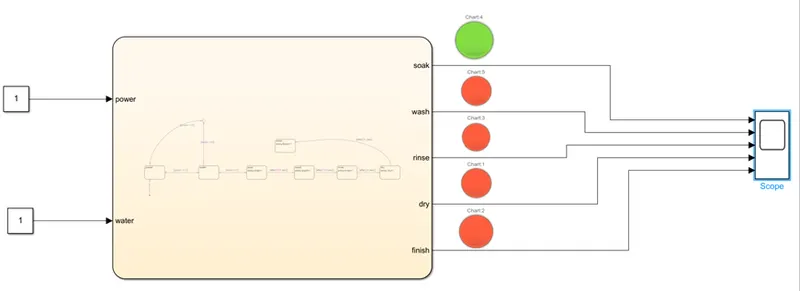
A Simulink model for operating the washing machine according to given conditions is shown below.
Power: ON, Water: OFF
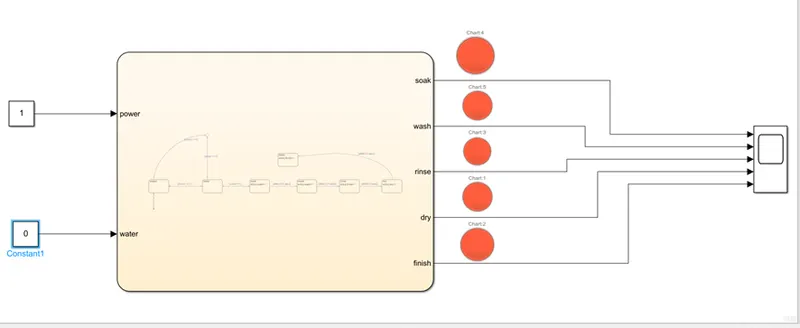
POWER: ON, WATER: OFF at t=0sec
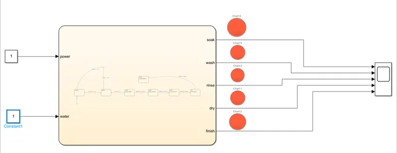
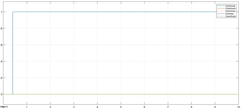
POWER: ON, WATER: ON, SOAK: ON at t=10sec
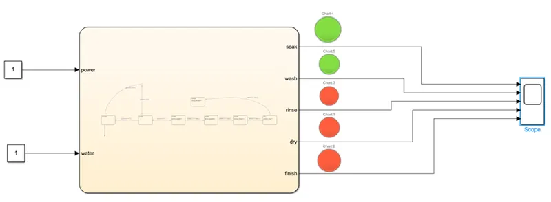
POWER: ON, WATER: ON, WASH: ON, at t=230sec
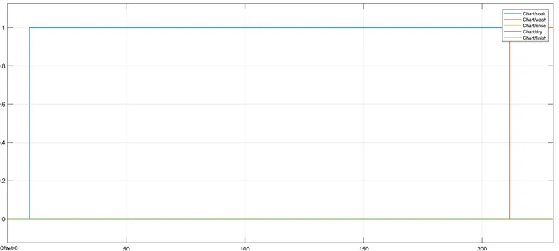
POWER: ON, WATER: ON, RINSE: ON at t=330sec
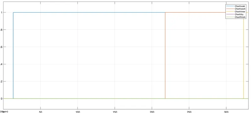
POWER: ON, WATER: ON, DRY: ON at t=350sec
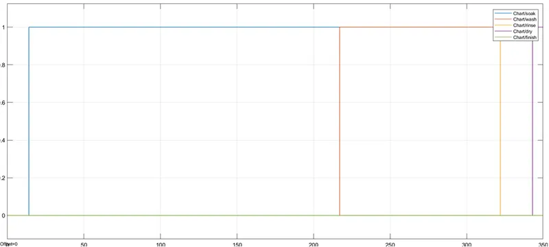
POWER: ON, WATER: ON, FINISH: ON at t=500sec

CONCLUSIONS AND RESULT:
Hence, the given problem was simulated for the washing machine along with the output diagrams and particular LED models and executing the Stateflow as per the given conditions.
2)MODEL DIAGRAM:
STATEFLOW:
MODEL EXPLANATION:
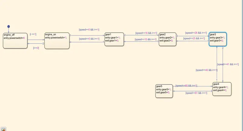
- In the above control logic, first engine is started from input switch [i==1] where I have used a constant block of value 1, which is the power switch to make engine ON. Next gear shift logic is implemented by following steps.
- Five gear conditions is created by the following values given and the above stateflow diagram is created.
The transition condition for the gear shift is decided as
0 to 15 G1
16 to 25 G2
26 to 40 G3
41 to 60 G4
Above 61 G5
SYMBOLS PANE:
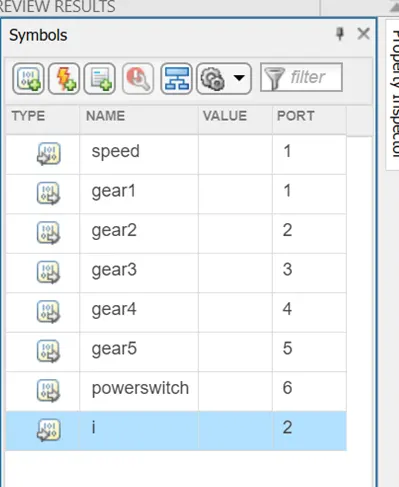
Here,
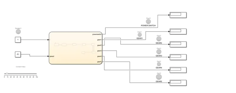
I(Ignition ON/OFF) and Speed is taken as input while all others like powerswitch, gear1 to gear5 are all the output data.
SIMULINK MODEL AT DIFFERENT SPEEDS:
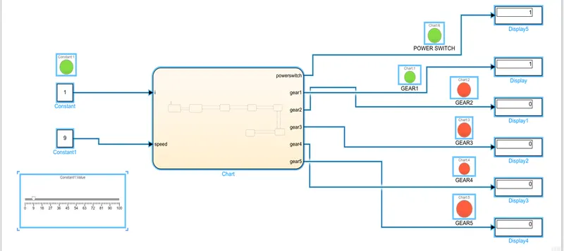
At SPEED 9 km/hr
GEAR1 is activated.
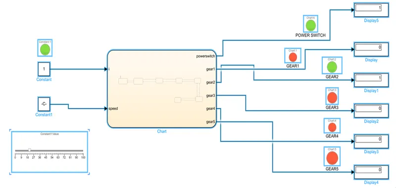
At SPEED 20 km/hr
GEAR2 is activated.
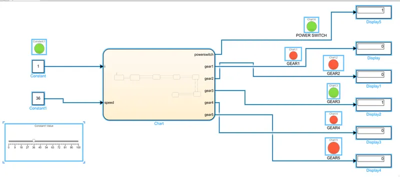
At SPEED 36 km/hr
GEAR3 is activated.
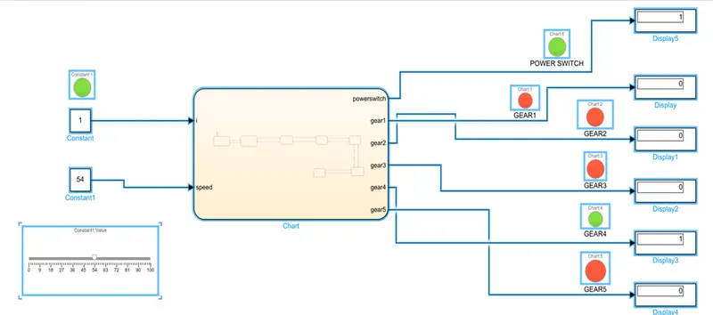
At SPEED 54 km/hr
GEAR4 is activated.
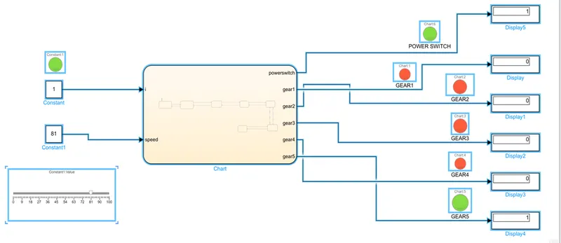
At SPEED 81 km/hr
GEAR5 is activated.
RESULT AND DISCUSSIONS:
We can see in the above Simulink diagrams, in which gear the car runs corresponding to its speed.
The respective green colour LED lamp is glown and the corresponding display with the value 1 is displayed w.r.t the gear shifting mechanism.
Therefore all the conditions are simulated through stateflow chart successfully and the results are satisfactory.