Week -2
AIM:
Make a Simulink model of doorbell using Solenoid block and to make a Simulink model of a thermistor to sense the temperature of heater and turn on or turn off the fan as per the temperature conditions.
DOORBELL USING SOLENOID:
The solenoid is an electromagnet. On passing current through the conducting wires a magnetic field is generated around it which attract magnetic materials. This phenomenon is used in the bell. When the switch is closed current flows through the circuit, exciting the electromagnet and pulling the plunger towards itself. This produces a ringing sound.
SIMULINK MODEL:
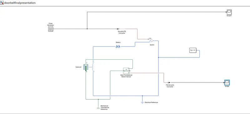
MODEL EXPLANATION:
Blocks used in the above model are Pulse Generator, Switch, Battery, Solenoid, Ideal Translational Motion Sensor, Mechanical Translational Reference, Electrical Reference, Scope, Simulink-PS converter, PS-Simulink converter, Solver Configuration.
The circuit connections of the blocks used in the model are clearly shown above.
A Pulse Generator Is given as input with the specifications mentioned below. The bell is engaged for 2s and then released. Same was implemented by giving period as 4 seconds and PW as 50% of 4 seconds i.e. 2 seconds. Phase delay is given as 2 seconds. Simulation starts from the unengaged condition of switch.
BLOCK PARAMETERS OF PULSE GENERATOR:
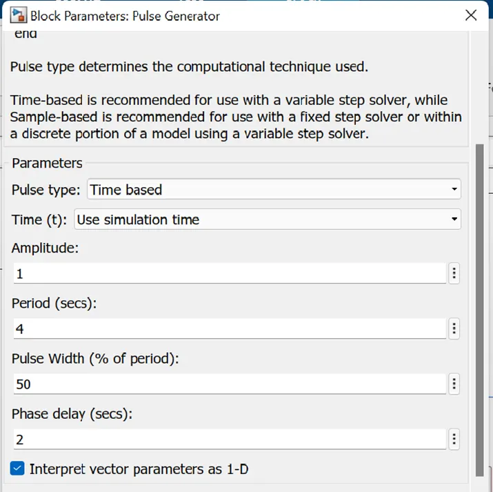
In the Simulink model I have used a pulse generator block as an input, for every 2 seconds its ON.Amplitude of 1 is selected.
OBSERVATION:
INPUT SIGNAL:
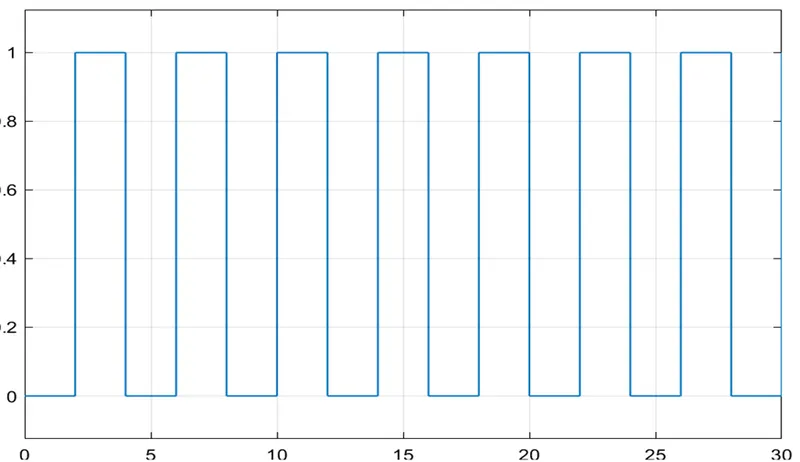
The above image shows the pulse pattern given as input. The cycle repeats for 30seconds.
As we want the circuit to be closed only in the interval of 2seconds a switch block is used. The switch block has a threshold value of 0.8. The threshold of the pulse generator is 1. The switch will only close if the value of threshold is more than 0.8. This then connected to solenoid block which contains the plunger arrangement. Initially when the plunger is away from C the value of X is 5mm and when it is close to C the value of X is 0mm. This can be seen from the output graph of plunger distance vs time. The position of the plunger is obtained by using the Ideal Translational Motion Sensor.
OUTPUT SIGNAL:
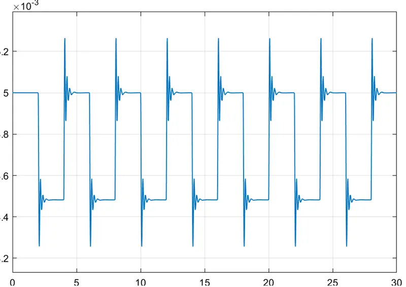
There are some spikes in the graph when switch is closed due to electromagnetic interference.
2.THERMISTOR MODEL
Conditions:
Temperature source:
20 °C from 0 to 10 seconds, 27 °C from 10 to 30 seconds, 23 °C from 30 to 50 seconds.
Fan conditions:
ON if the temperature above 25 °C, OFF otherwise.
BLOCKS USED IN MODEL:
- Repeating Sequence Stair
- Controlled temperature source
- Thermistor
- Resistor
- Voltage Sensor
- Battery
- Switch
- Scope
- Display
- PS Simulink Converter
- Simulink PS converter
- Solver Configuration
SIMULINK MODEL:
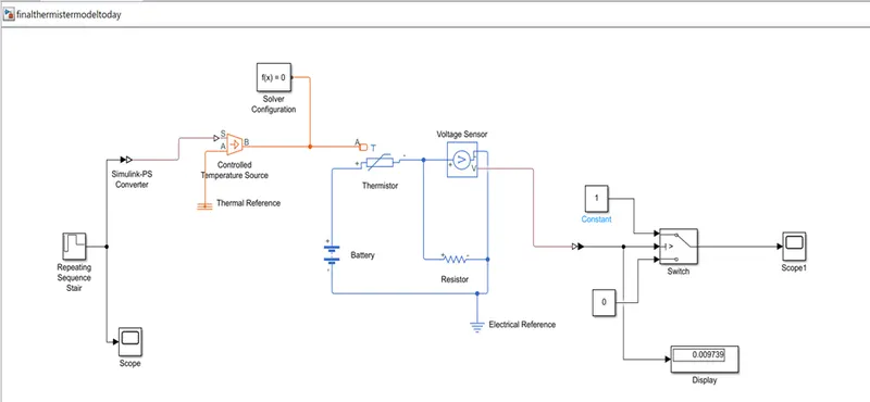
MODEL EXPLANATION:
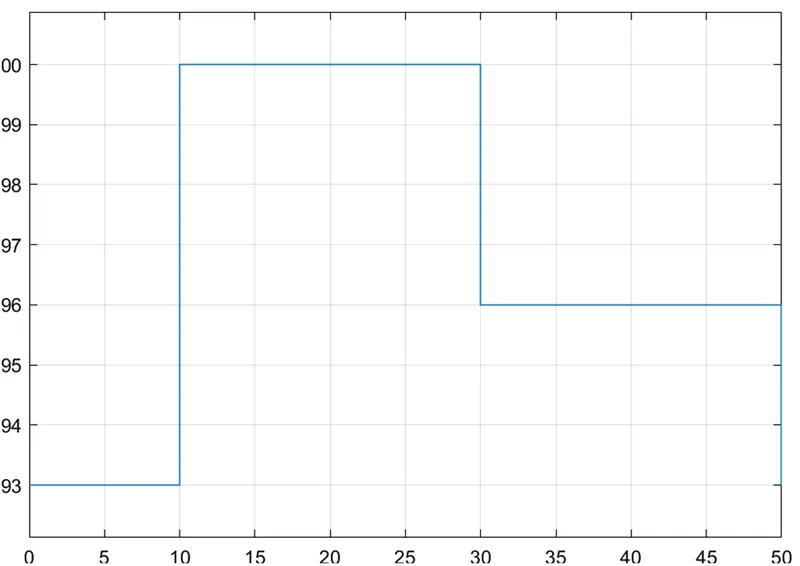
- We give 5 temperature inputs at every 10 seconds i.e. for 50 seconds. We give temperatures in Kelvin. Temperatures are 293,300,300,296,296 for every 10 seconds.
- Add signal repeating sequence stair block for input temperatures. Give temperatures as above and sample time as 10seconds. Here sample time means, each value of temperature at a certain time period.
- Connect scope to the Repeated Sequence Stair Block to get the input graph.
- Add Controlled Temperature Source Block for maintaining temperature. Connect Simulink-PS Converter as shown in the diagram to convert Simulink system to physical system.
- Add Temperature Reference block and join with point ‘A’.
- Add Thermistor block and join the point ‘A’ with point ‘B’ of the source block.
- Add Battery block for the supply of current in the circuit.
- Add Voltage Sensor block and Resistor block and join with the thermistor. To the electrical system add an electric reference block.
- Join all the connections as shown in the figure.
- Since we need to operate in ON and OFF conditions, we add a switch block with inputs. Inputs are given as 0 and 1 with two constant blocks.
- Join point ‘V’ of voltage sensor to the switch. The switch operates in the values between 0 and 1. PS-Simulink Converter is used to connect it.
- We use display block to know the threshold value of the switch. Scope is connected to know the output graph from the switch.
- Join the solver Configuration block as shown.
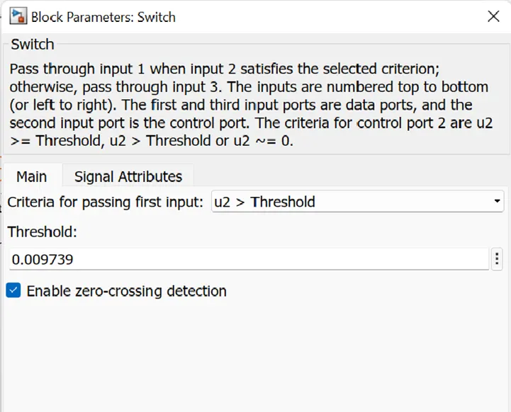
- Run the simulation under 50 seconds. We get a value in the display, copy the value and paste it in the Switch block Threshold value.
- Run the model again for 50 seconds to know the output.
- The output is known in the scope. Double click on it and the output will be available.
INPUT SCOPE:
We can observe 50 seconds of time in x-axis and temperature on y-axis. The below plot shows the temperature in Kelvin at different time mentioned in the question.
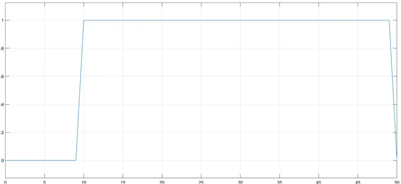
OUTPUT SCOPE:
We can observe from the graph that, when the temperature is 293K, the fan was OFF for 10 seconds. When the temperature reached 298K, the fan gets turned ON for the next 20 seconds. And when the temperature again reaches to 293K fan gets Turn OFF.
RESULT AND CONCLUSION FOR BOTH THE EXPERIMENTS:
1] In the first part, we used a solenoid to make a Simulink model of a Doorbell, here we can conclude that the plunger is moving from its initial position of 5mm with a time delay of 2seconds, this time delay happens while the plunger is suddenly disconnecting from the bell and moving away.
2] In the second model, we use Thermistor to sense the temperature and according to our condition, we put the threshold value to the switch block to turn ON and turn OFF the fan at a particular temperature.