Week-6 Challenge: EV Drivetrain
1)
Aim:
To analyse types of power converter circuits used in electric and hybrid vehicle.
Principle:
A DC/DC converter in its basic form converts unregulated DC input voltage at a certain level to a regulated DC output voltage at a different level with very highconversion efficiency (>90%).
The DC/ DC converters used in EVs is used for:
- Providing low voltage (12V or 14V) for low voltage loads.
- Boosting the voltage level of the battery such that it matches the level of the
DC bus voltage for driving the AC motor inverter if the traction motor is AC
motor. - Motor propulsion if the traction motor is a DC motor.
Explaination:
DC/DC Converters used for supplying Low Voltage Loads:
PWM DC-DC Converter:
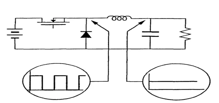
- The converter operates by repetitively switching between two topologies.
- When the active switch is ON the converter elements are connected in one topology and when and diode is ON the
converter elements are connected in a different topology. - This switching actionconverts the input DC voltage into a pulsating voltage.
Quasi Resonant Converters:
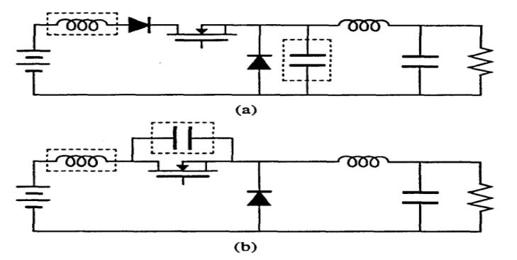
- Quasi-resonant converters are derived from PWM converters by employing resonant circuits to modify the switching behavior of the semiconductor devices.
- There are two types of quasi-resonant converters namely the zero-current-switched quasi-resonant converters (ZCS QRC) and zero-voltage-switched quasi- resonant converters (ZVS QRC).
- The output voltages of both converters are controlled by controlling the switching frequency.
- The energy stored in the switch as a result of the parasitic output capacitance is dissipated in the switch each time the switch is turned on.
- The turn-on loss of a switch due to the energy stored in the parasitic output capacitance can be minimized by using this capacitance as a part of the resonant circuit and turning the switch on at zero voltage.
- This principle is also employed in a zero-voltage-switched quasi-resonant converter.
Zero Voltage Switched Multi Resonant Converter:
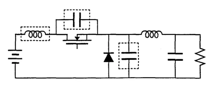
- A zero-voltage-switched multi-resonant converter (ZVS-MRC) absorbs both the parasitic output capacitance of the active switch and the parasitic junction capacitance of the rectifying diode thus providing favorable switching conditions for both devices.
- Such a converter is derived from a PWM converter by introducing an inductor in the circuit such that it forms resonant circuits with the parasitic output capacitance of the active switch and parasitic junction capacitance of the rectifying diode.
- As in the case of zero-current-switched and zero-voltage-switched quasi-resonant converters the output voltage of a zero-voltage-switched multi-resonant converter is controlled by controlling the switching frequency.
Resonant Converters:
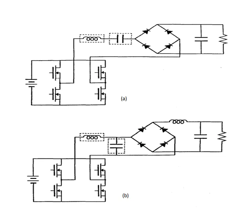
- Resonant converters employ resonant circuits to achieve soft switching of devices.
- In the case of resonant DC-to-DC converters, the voltages or currents of the resonant circuits are rectified.
- The circuits of two of the basic resonant converters namely the series and parallel resonant converters.
- In the series resonant converter the resonant current is rectified whereas in the parallel resonant converter the resonant voltage is rectified.
- Constant-frequency operation of resonant converters which employ full-bridge arrangement of switches is possible.
- The switches in constant-frequency resonant converters operate at 50 % duty-ratio.
- However the phase between the drive signals of diagonally opposite switches of these converters can be controlled to control the voltage applied to the resonant circuit.
- This allows the operation of resonant converters at constant frequency.
- Resonant converters operate with low switching losses.
Soft Switched PWM Converters:
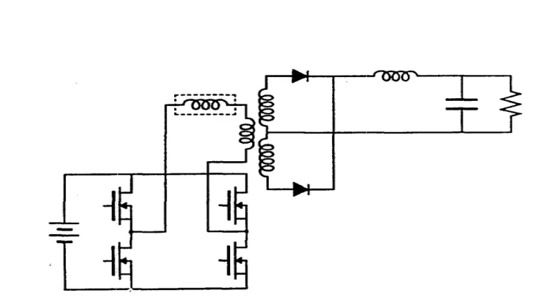
- PWM converters have low voltage and current stresses, and hence, low conduction losses.
- The principle of resonance can be employed to achieve zero-current or zero voltage switching to reduce the switching losses of converters.
- Thus the switching losses of a converter can be significantly reduced if the converter operates as a PWM converter for most of the time during a switching period and employs resonance only during transitions between the on and off states.
- This converter employs the leakage inductance of the transformer and the parasitic output capacitances of the
devices to achieve zero-voltage switching of devices.
Zero Voltage Switched and Zero Current Switched PWM Converters:
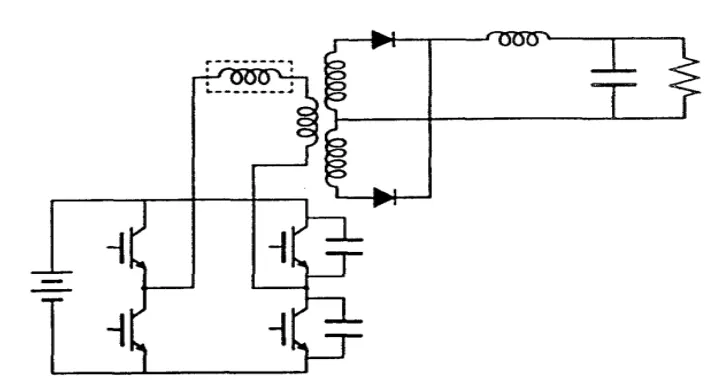
- The inductor inside the dashed box represents the leakage inductance of the transformer.
- The IGBT bridge in this converter does not employ anti-parallel diodes and is controlled such that two of the
four devices of the bridge switch at zero voltage and the remaining two switch at zero current.
DC/DC Converters used for boosting the battery voltage:
Non-isolated Bidirectional Half Bridge DC/DC Converter:
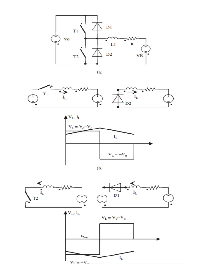
- DC/DC converters such as buck and boost converters do not have bidirectional power flow capability.
- This limitation is due to the presence of diodes in their structure which prevents reverse current flow.
- A unidirectional DC/DC converter can be turned into a bidirectional converter by replacing the diodes with a controllable switch in its structure.
Isolated Bidirectional Full Bridge DC/DC Converter:
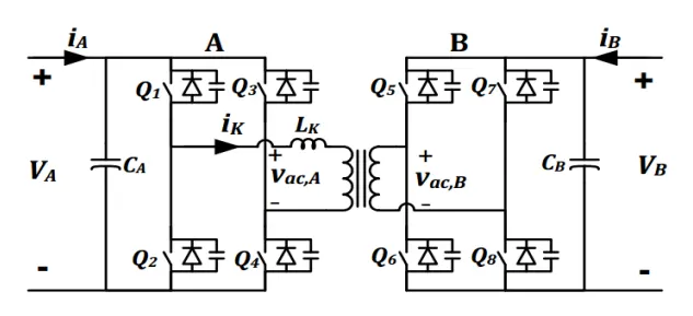
- Full-bridge voltage-fed converters are used at both sides of the isolation transformer and the control is performed based on soft switched phase-shift strategy.
- The diagonal switching pairs in each converter are turned on simultaneously with 50% duty cycle (ignoring the small deadtime) and with 1800 phase shift between two legs to provide a nearly square wave AC voltage across transformer terminals.
- The phase shift between two AC voltages denoted by φ, is an important parameter which determines the direction and amount of power transfer between DC buses.
- By adjusting this phase shift, a fixed frequency operation with full control over the power transfer is possible.
Isolated Bidirectional Dual Half Bridge DC/DC Converter:
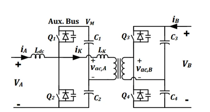
- This topology consists of one voltage-fed half bridge converter in Side B and a modified current-fed half bridge converter in Side A.
- The current-fed side is the lower voltage side because it usually consists of battery or ultra-capacitor DC energy sources in which low ripple current is desirable.
- In practice the voltage amplitude is a few tens of volts for the low voltage side (battery or ultra-capacitor) and a few hundreds of volts for the high voltage side.
Interleaved DC/DC Converter:
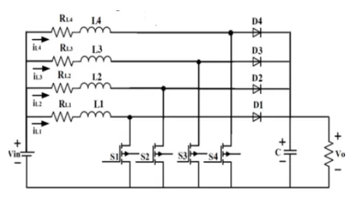
- It consists of "n" numbers of DC/DC boost converters connected in parallel.
- The main goal of this converter is to reduce the size of the passive components by "n" times compared to the conventional boost converter (BC).
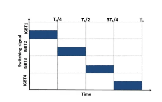
- Therefore, system reliability and converter power rating are increased by using the parallel phases.
DC/DC Converters used for DC Motor Drives:
Two-Quadrant Zero-Voltage-Switching Multi-Resonant (2Q-ZVS-MR) Converter:
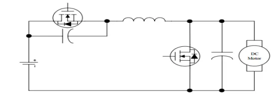
- The 2Q–ZV–MR converter is created by adding a resonant inductor and two resonant capacitors to a conventional 2Q–PWM DC drive.
- The major advantages of this converter are ZVS operation of both power switches full ranges of voltage conversion-ratio and load constant-frequency operation capability of short-circuit operation and absorption of all major parasitics.
- Due to the high circulating energy and hence the conduction losses are significantly increased resulting the power devices and other circuit components to be rated for higher VA ratings as compared with their PWM counterpart.
Two-Quadrant Zero-Voltage-Transition (2Q-ZVT) Converter:
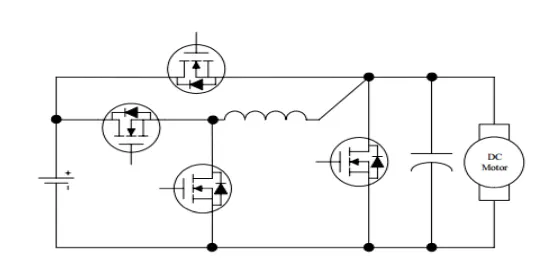
- A two-quadrant zero-voltage-transition (2Q-ZVT) converter has been specially developed for DC motor drives.
- The 2Q-ZVT converter is created by adding a resonant inductor a resonant capacitor and two auxiliary switches to a conventional 2Q-PWM DC drive.
- It possesses the advantages that both the main switches and diodes can switch with ZVS and unity device stresses during both the motoring and regenerating modes of operation.
- It also offers a simple circuit topology and low cost, leading to achieve high switching frequency, high power density, and high efficiency.
Two-Quadrant Zero-Current-Transition (2Q-ZCT) Converter:
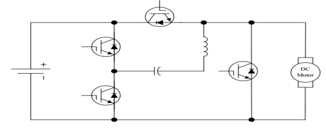
- A two-quadrant zero-current-transition (2Q-ZCT) converter has also been proposed for DC motor drives.
- It is created by adding a resonant inductor, a resonant capacitor and two auxiliary switches to a conventional 2Q-PWM DC drive.
- This converter possesses the advantages that both the main and auxiliary switches can operate with zero-current switching (ZCS) during both the motoring and regenerating modes.
- It takes the role to be particularly useful for those IGBT-based DC motor drive applications, which generally suffer from severe inductive turn-off switching losses.
DC/AC Converters:
- A suitable DC/AC inverter draws DC power from the batteries to drive the electric traction motor which in turn provides power to the wheels.
H-Bridge Topology with Single DC link:
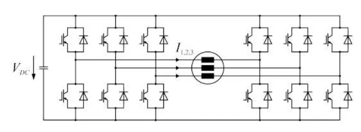
- The H-bridge with single DC link behaves similar to a VSI at 2VDC with sine-triangle modulation in PWM mode
and an on-time of 1200 in block mode. - In terms of voltage increase and SUR, the H-bridge with two electrically isolated DC links can be considered as the combination of two independent VSIs, thus doubling the voltage while keeping the SUR constant. Here, switching losses can be reduced by always operating one converter in block mode.
- Aspects in favor of an H-bridge topology may in certain cases outweigh the additional effort and losses (in case of a
single DC link). - Due to the higher phase voltage of an H-bridge inverter, eddy current losses in the windings can potentially be reduced.
- Without adjusting the machine, the high-speed power output can be increased.
Auxiliary Resonant Commutated Pole Inverter:
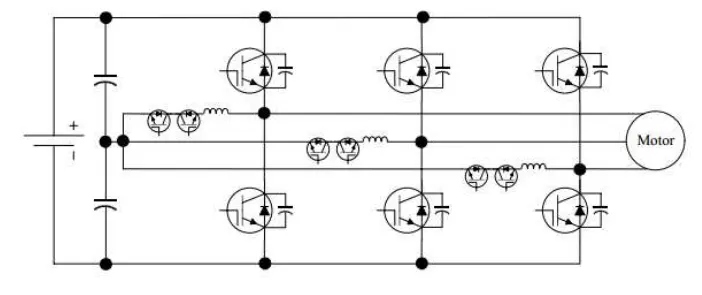
- A bidirectional switch is series connected to the resonant inductor to control the direction of resonant energy
transfer. - These auxiliary switches are operated with ZCS and required to withstand only half of the DC source voltage.
- Since the auxiliary switches are not associated with any load energy transfer, their power ratings are much smaller than the main power devices.
Multilevel Inverters:
Cascaded H-Bridge Multilevel Inverter:
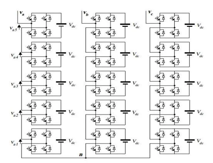
- It consists of a series of H-bridge (single phase full bridge) inverter units in each of its three phases.
- An 11-level phase neutral cascade inverter connected in star configuration.
- Each H-bridge unit has its own DC source (battery unit in EVs).
- One H-bridge with its associated gating signals and output voltage.
- The output voltage of the inverter is almost sinusoidal and it has less than 5% THD.
2)
Aim:
To find the Electric Vehicle steady state speed if duty cycle is 70%.
Given data:
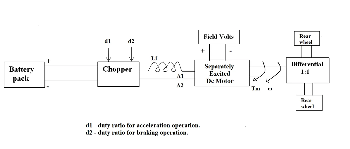
Battery pack=72 V

Rated Armature voltage=72 V

Rated armature current=400 A

Ra=0.5Ω

KΦ=0.7 Volt second

Chopper Switching frequency=400 Hz
The vehicle speed-torque characteristics are given by the below equation

Solution:
D= Ton/T
where,
D= Dutycycle
Ton= On time of the switch
T= Total time of the switch

T=(1/f)
where,
f= switching frequency
T= total time

T=(1/400)
T= 0.0025 sec

(70/100)= ON/(1/400)
Ton= 0.00175 sec

Toff= T-Ton
Toff= 0.0025-0.00175
Toff= 0.00075 sec

Vo= f*Ton*Vs
Where,
Vo= Output voltage from chopper
Vs= Supply voltage into chopper
f= Switching frequency
Ton= On time of chopper
Vo= 400*0.00175*72
Vo= 50.4 V

Given the vehicle torque speed equation :
Tv=24.7+0.0051w^2.................................(1)

Motor torque speed equation:
w=(V/k0)-(Ra/k0^2)*T
substituting the values we get,
Tm=70.560-0.98w....................................(2)

Tm=Tv
70.560-24.7=0.980w+0.0051w^2
w1=38.917
w2=-231.074

Therefore the steady state speed of vehicle is 38.917 rad/sec
Result:
Thus the Electric Vehicle steady state speed on duty cycle is 70% is 38.917 rad/sec.
3)
Aim:
To develop a mathematical model of a DC Motor for the below equation using simulink.
ω= V/Kϕ -Ra/Kϕ^2 .T
Simulation:
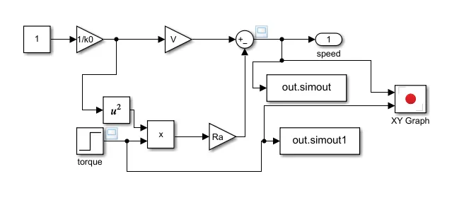
- The above image represents the mathematical model of torque-speed equation of dc motor using simulink.
- The value of constant parameters such as the value of Ra, V, K0 etc are uploaded in the gain block.

- These values gets stored in the workspace.
- As per the motor torque-speed equations the connection are given.
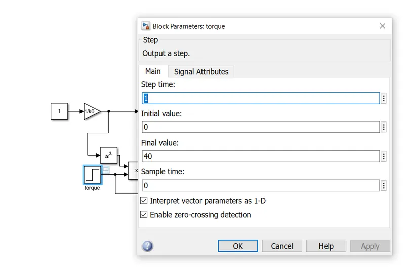
- Using the step block, the torque value is varied and the speed-torque output is viewed using XY graph respectively.
Output:

- For the given torque input of 40 Nm we obtained 120 rad/sec.
Result:
To develop a mathematical model of a DC Motor using simulink is done.
4)
Aim:
To study and explain the comparison of Induction vs DC brushless motors by Wally Rippel, Tesla.
Explaination:
Brushless DC motor:
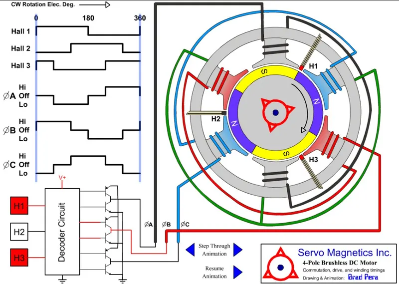
- In brushless machines the rotor includes two or more permanent magnets that generate a DC magnetic field.
- These magnetic field enters the stator core and interacts with currents flowing within the windings to produce a torque interaction between the rotor and stator.
- The magnitude and polarity of the stator is varied such that the torque remains constant and the conversion of electrical to mechanical energy is optimally efficient by controling current through the inverter.
- No starting torque is produced unless an inverter is connected to maintain the angular position of the rotor.
- Less amount of rotor heat is generated with the DC brushless drive.
- Rotor cooling is easier and can operate in unity power factor.
- Since the permanent magnets are used in rotors , there is no easy way of varying the magnetic flux.
- As machine size grows, the magnetic losses increase proportionately and part load efficiency drops.
- Permanent magnets are expensive an also difficult to handle due to very large forces that come into play when any ferromagnetic materials get close to them.
Induction Motor:
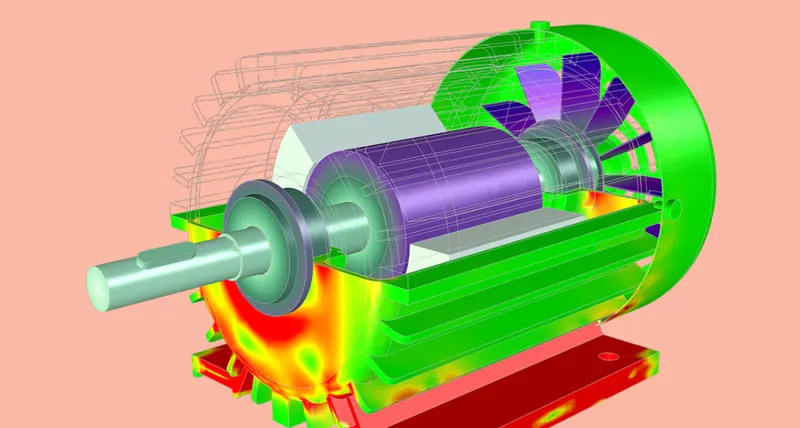
- The induction rotor has no magnets but has stacked steel laminations with buried peripheral conductors that form a shorted structure.
- Currents flowing in the stator windings produce a rotating magnetic field that enters the rotor.
- The frequency of this magnetic field is equal to the difference between the applied electrical frequency and the rotational frequency of the rotor itself.
- These currents interact with the original magnetic field to produce forces.
- No inverter is required and the induction motors are directly compatible with conventional utility power.
- They cannot operate from DC.
- Since the shaft speed is proportionate to line frequency, when used with utility power, they are constant speed machines.
- By adding an inverter (without any feedback control) and it becomes possible to power an induction machine from a battery.
- Induction machines have no magnets and flux density fields are adjustable.
- The magnetic losses are reduced and efficiency is maximized.
- As the size of the machine increases, losses do not increase.
- cost advantage over PM machines
- Since the permanent magnets are not used , its cost is reduced.
- Achieving stability over the entire torque-speed range and over temperature is more difficult with induction motors i.e difficult to control.
Conclusion:
- DC brushless drives will continue to dominate in the hybrid and coming plug-in hybrid vehicles.
- Induction drives will likely to maintain dominance for the high-performance in pure electric vehicles.
Attachments:
https://drive.google.com/file/d/1hi9DMzJMfZtCAP0kMAjMXGmCegzJmNrN/view?usp=sharing