Week-6 Challenge: EV Drivetrain
(1) Which types of power converter circuits are employed in electric and hybrid electric vehicle?
Hybrid electric vehicle: HEV is the hybrid vehicle that’s combine electric motor system with internal combustion engine. The presence of electric powertrain to achieve better fuel economy or better performance. All energy of battery charged through regenerative braking, otherwise lost the energy in braking to assist gasoline engine during acceleration condition.
Electric vehicle: it is also called battery electric vehicle, EV are fully electric vehicle with rechargeable battery. In this vehicle uses one or more electric motor or traction motor for propulsion. All energy to run the vehicle comes from the battery pack which recharged from the grid.
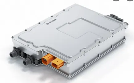
- DC to AC converter(inverter):
DC to AC converter used that converts DC power from battery to AC power used in electric motor. Uses of inverter can increase and decrease power and torque of motor by adjusting amplitude of signal.
- AC to DC converter (rectifier):
It converts power from AC to DC and then feed to car battery. This is most common method used in electric vehicle charging. Battery stores energy in form of DC so AC to DC power converter used in PEV vehicle.
- DC to DC converter (chopper):
DC to DC converter are classified in unidirectional and bidirectional converters. Unidirectional converter used in Electric vehicle various load such as sensors, control, safety equipment, dc motor drive and electric traction. and bidirectional converter used in battery charging, regenerative braking and back up power.
- Buck converter:
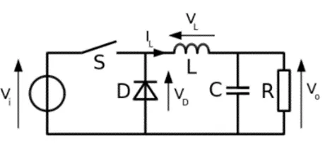
Buck converter is the step down converter used in DC to DC power converter which step down the voltage from input supply to output connected load.
- Boost converter:
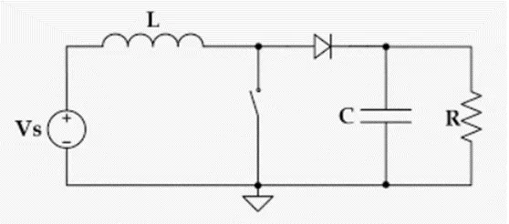
Boost converter is the step up converter used DC to DC converter which step up voltage from input supply to output connected load.
- Cuk converter:
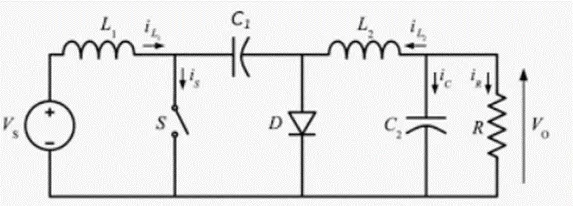
Cuk converter is the combination of boost converter and buck converter, having one switching device and a mutual capacitor, to couple the energy. cuk converter has zero ripple currents.
- Buck -boost converter
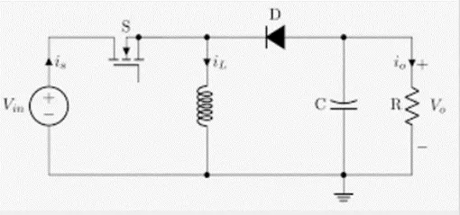
It is a type of DC to DC converter has a output voltage magnitude that either greater than or less than input voltage magnitude.
- Charge pump converter:
This DC to DC converter used in capacitors for energetic charged storage for higher and lower voltage. charge pump circuits has a higher efficiency.
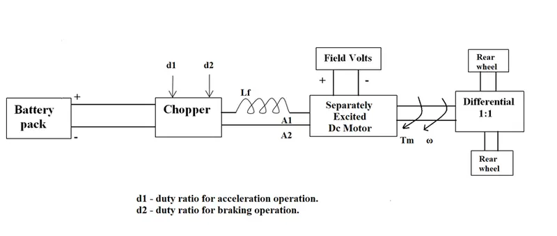
(2) An Electric Vehicle's powertrain with 72V battery pack in shown in the diagram below. The duty ratio for acceleration operation is 'd1' and for the braking operation the duty ratio is 'd2'.
Solution:

Given:
Rated armature voltage= 72v
Rated armature current =400z
Armature resistance=0.5
K_ɸ=0.7volt
Chopper switching frequency= 400 Hz
Vehicle speed torque characteristics =   T_v=24.7+(0.0051)W^2
Duty cycle = 70% = 0.7
Actual voltage= duty cycle*rated armature voltage
                       = 0.7*72
                       = 50.4 volt
Torque speed characteristics Equation:
T=  〖VK〗_ɸ/R_a   -  〖Kɸ〗^2/R_a *w

T=  (50.4*0.7)/0.5  -  〖0.7〗^2/0.5*w

                                                  T = 70.56 – 0.98W …. ……………………………. (1)
Given Torque speed equation = T_v=24.7+(0.0051)W^2……………………… (2)
Solving Equation (1) & (2)
  24.7+(0.0051) W^(2  =)  70.56 – 0.98W
(0.0051) W^2+ 0.98W -45.86=0…………….. (3)
Solving Equation (3) using Quadratic equation formula
w=  (-b±√(b^2-4ac))/2a
w= (-0.98±√(〖0.98〗^2-4*0.0051*(-45.86)))/(2*0.0051)
w= 38.91498 rad/sec  & w= -231.0718 rad/sec
 speed of the EV of duty cycle 70% = 38.91498
38.914 rad/sec = 371.20 RPM
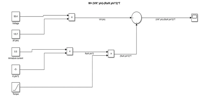
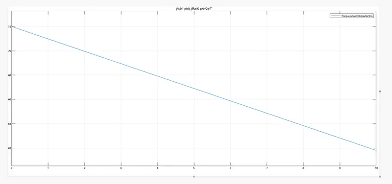
(3) Develop a mathematical model of a DC Motor for the below equation using Simulink.
ω= V/Kϕ -Ra/Kϕ^2 .T
Simulink model:
Result:
- Refer to the blog on below topic:
Induction Versus DC brushless motors by Wally Rippel, Tesla
Explain in brief about author’s perspective.
According to authors perspective he explaining compare induction verses DC brushless motor in above topic. Firstly author explaining DC brushless motor parts and specification. Then author explain components and working of induction motors.
Then he compared induction and DC brushless motor mentioned that 3 phase induction motor can produced torque output torque and induction motor starts under the load without any inverter and dc brushless motor no starting torque produced and inverter needed to start under no load.
Then authors discuss induction motor limitation, induction motor not operates in DC supply, operating induction motor AC supply must.
Then authors explain similarity and difference such as both motor drive has similar stator, both drives used 3 phase modulating inverter only difference is rotor and inverter control.
Then authors explaining losses and efficiency of the induction and brushless motor. Brushless motor operates unity power factor and induction motor operates 85 power factor, and also conclude few percentage points DC brushless drive better than induction motor drive.
After authors explaining some advantages of induction motor over DC brushless motor, induction motor has no magnets field is magnetic field strength are adjustable so losses is less and efficiency is increased.
Then authors differentiate on the basis of cost induction motor are better because permanents magnets are expensive. But on the basis of controlling induction motor are difficult to control over DC brushless motor.
At the end authors conclude DC brushless drives are used in hybrid and plug in hybrid vehicle and induction motor drive are used in pure electric vehicle.