Week-6 Challenge: EV Drivetrain
Q1.
Ans: -
Power Electronics is defined as the application of solid -state (devices) electronics for the control and conversion of electric power. We use different types of semiconductors to create power converter circuits
1. AC to DC Converter (Controlled Rectifier): -
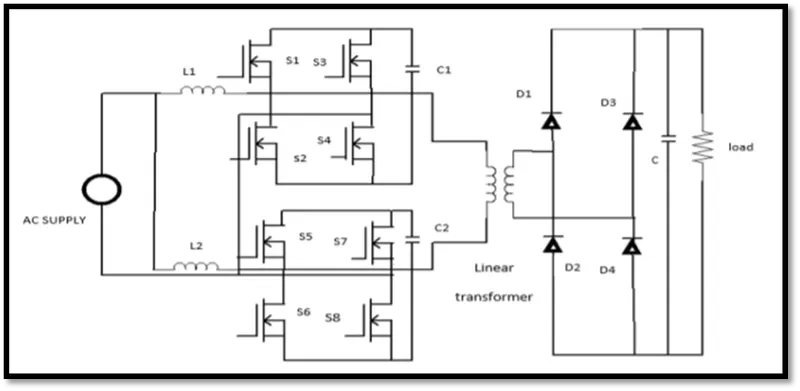
An AC to DC converter circuit can convert AC voltage into a DC voltage. The DC output voltage can be controlled by varying the firing angle of the thyristors. The AC input voltage could be a single phase or three phase.
The prime source of electrical power coming from the grid is single/three-phase alternating current. While AC current is efficient for transmission purposes, many devices, drives, and electronic equipment require DC power supply that is fulfilled using rectifiers.
AC to DC Converter is further classified as:
- Diode Rectifiers: - This rectifier circuit changes applied ac input voltage into a fixed dc voltage. Either a single-phase or three-phase ac signal is applied at the input.
- Phase Controlled Rectifiers: -phase-controlled rectifiers are designed to convert a fixed value of ac signal voltage into a variable dc voltage.
2. DC to DC Converter (DC Chopper): -
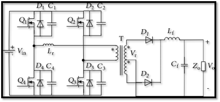
In many industrial applications, DC-DC converters are required to convert a fixed-voltage DC source into a variable-voltage DC source. Like a transformer, DC-DC converter can be used to step down or step up a DC voltage source.
Application: Traction motor control in electric automobiles, trolley cars, marine hoists, forklift trucks, mine haulers, etc
Advantages: High Efficiency and fast dynamic response
DC to DC Converter is further classified as:
- Buck converter (step down): A converter which provides output voltage less than the input.
- Boost converter (step up): A converter whose output is higher than the input.
- Buck-Boost converter: A converter whose output can either be higher or lower than the input.
The converter switch SW can be implemented by using Transistor, MOSFET, GTO, IGBT, BJT, etc.
3. DC to AC Converter (Inverter): -
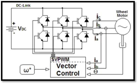
The devices that are designed to convert the dc signal into ac signal are known as inverters. The applied input is a fixed dc voltage that can be obtained from batteries but the output obtained is variable ac voltage.
Generally, the semiconductor devices used for its fabrication are power transistors, MOSFETs, IGBT, GTO, thyristors, etc.
DC to AC Converter is further classified as:
- Voltage source inverter
- Current source inverter
4. AC to AC Converter (AC voltage regulator): -
An ac-to-ac converter is designed to change the ac signal of fixed frequency into a variable ac output voltage.
AC to AC Converter is further classified as:
- Cycloconverters: - Applications in slow-speed large AC traction drives such as a rotary kiln, multi-MW ac motor drives, etc.
- AC Voltage Controllers (AC voltage regulators): - Applications of ac voltage controllers are in lighting control, electronic tap changers, speed control of large fans and pumps as well.
Q.2
Ans: -
Given,
Motor and Controller Parameters:
Rated Armature voltage= 72 V
Rated armature current= 400 A
Ra= 0.5Ω, KΦ= 0.7 Volt second
Chopper Switching frequency= 400 Hz
The vehicle speed-torque characteristics are given by the equation below
`Tv=24.7+(0.0051) w^2`
What is EV steady state speed if duty cycle is 70%?
Duty cycle here is 70% so,
V = 0.7*72 =50.4 volts
Kphi = 0.7 V-s
Ra = 0.5 ohm
We know dc motor speed equation
`ω=(V/Kphi)-(Ra/(Kphi^2 ))*T`
Then
`T=(V-ω*Kphi)/R*Kphi`
`T=(50.4-ω*0.7)/0.5*0.7`
`T=70.56-0.98ω`
Equating both side RHS = LHS,
`70.56-0.98ω^2=0.0051ω^2+24.7`
`0.0051ω^2+0.98ω-45.86`
We get quadratic equation to solve we use Quadratic formula
`x=((-b±√(b^2-4ac)))/2a`
`x=((-0.98±√(0.98)^2-4(0.0051)*(-45.86)))/(2*0.0051)`
`x=((-0.98±1.377)/0.0102)`
`x=((-0.98)+1.377)/0.0102 ) and x=((-0.98-1.377)/0.0102)`
So we have two solutions
W = 38.92 rad/s and w = -231.08 rad/s
But the angular velocity is scalar quantity so
W =38.92 rad/s
W = 371.65 =372 rpm
EV steady state speed if duty cycle is 70% is 372 rpm.
REFERENCE: -
https://en.wikipedia.org/wiki/Motor_constants
Q3.
Ans: -
We consider the above question data,
V = 0.7*72 =50.4 v
Kphi = 0.7 V-s
Ra = 0.5 ohm
- Simulink model: -
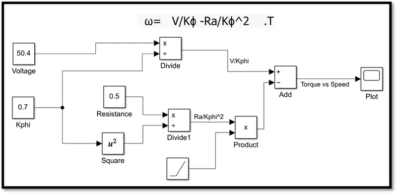
- Here we are used constant block to give input to equation.
- We used ramp block to give input for torque so we can get value for different input.
- We used product block to multiplication.
- We used divide block to divide the inputs.
- Lastly, we used scope block to see results.
- Output: -
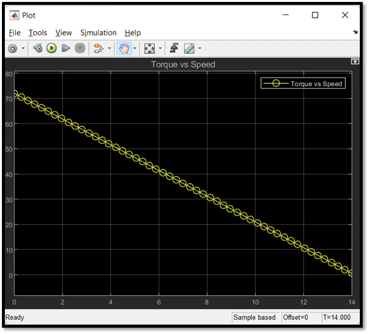
Here we can see that if speed increased torque will decrease and if speed decrease torque will increase. So, we can say that speed is inversely proportional to torque. At different condition with load requirement, we can either get maximum torque or maximum speed.
Q4.
Ans: - https://www.tesla.com/blog/induction-versus-dc-brushless-motors
In the above article of induction-versus-dc-brushless-motors the Author giving brief info about motor used in Electric Vehicle. Authors giving more importance only for inductance motor and BLDC motor. He Also compare the both motors with limitations and advantage. He is giving a look at the development of motors in electric vehicles.
The following are the important points which the Author discusses in the above article,
- There is not one best engine type, rather there are different types of engines to suit personal requirements, such as price and performance. This is also true for electric vehicle drives.
- Research and Development happened in future era vanished the older development replace with new one. For example, Lead has been replaced by lithium and DC by either DC brushless or induction. Contactors, meanwhile, have given way to modulating inverters. So, will each of these elements also become obsolete in the near future?
- BLDC motor: -
This motor includes the rotor includes two or more permanent magnets that generate a DC magnetic field (as seen from the vantage point of the rotor). In turn, this magnetic field enters the stator core (a core made up of thin, stacked laminations) and interacts with currents flowing within the windings to produce a torque interaction between the rotor and stator. As the rotor rotates, it is necessary that the magnitude and polarity of the stator currents be continuously varied – and in just the right way - such that the torque remains constant and the conversion of electrical to mechanical energy is optimally efficient. The device that provides this current control is called an inverter. Without it, brushless motors are useless motors.
a brushless DC motor produces no starting torque when directly connected to fixed frequency utility power. They really need the aid of an inverter whose “phase” is maintained in step with the angular position of the rotor.
- Induction motor: -
The stators for the 3-phase induction motor and the DC brushless motor are virtually identical. Both have three sets of “distributed windings” that are inserted within the stator core. The essential difference between the two machines is with the rotor.
the induction rotor has no magnets just stacked steel laminations with buried peripheral conductors that form a “shorted structure.” Currents flowing in the stator windings produce a rotating magnetic field that enters the rotor. In turn, the frequency of this magnetic field as “seen” by the rotor is equal to the difference between the applied electrical frequency and the rotational “frequency” of the rotor itself. Accordingly, an induced voltage exists across the shorted structure that is proportionate to this speed difference between the rotor and electrical frequency. In response to this voltage, currents are produced within the rotor conductors that are approximately proportionate to the voltage, hence the speed difference. Finally, these currents interact with the original magnetic field to produce forces – a component of which is the desired rotor torque. When a 3-phase induction motor is connected to utility type 3-phase power, torque is produced at the outset; the motor has the ability to start under load. No inverter is needed.
3-phase induction motors have great utility, they also have some severe limitations. They cannot operate from DC; AC is a must. Shaft speed is proportionate to line frequency. Hence, when used with utility power, they are constant speed machines. Finally, when operated from utility power, they have limited starting torque and somewhat limited running peak torque capabilities, when compared to DC type machines.
Add an inverter (without any feedback control) and it becomes possible to power an induction machine from a battery or other DC source; variable speed also becomes possible simply by adjusting the inverter frequency. Still, torque performance is low compared with DC machines. Add some feedback loops such that the inverter produces the exact frequency that the motor “desires,” and the induction motor is now capable of competing with DC and DC brushless for vehicle applications.
- Comparison of BLDC and INDUCTION motor: -
- DC brushless drives require an absolute position sensor, while induction drives require only a speed sensor
- In an ideal brushless drive, the strength of the magnetic field produced by the permanent magnets would be adjustable. When maximum torque is required, especially at low speeds, the magnetic field strength (B) should be maximum – so that inverter and motor currents are maintained at their lowest possible values. This minimizes the I² R (current² resistance) losses and thereby optimizes efficiency.
- When torque levels are low, the B field should be reduced such that eddy and hysteresis losses due to B are also reduced. Ideally, B should be adjusted such that the sum of the eddy, hysteresis, and I² losses is minimized. Unfortunately, there is no easy way of changing B with permanent magnets.
- In contrast, induction machines have no magnets and B fields are “adjustable,” since B is proportionate to V/f (voltage to frequency). This means that at light loads the inverter can reduce voltage such that magnetic losses are reduced and efficiency is maximized. Thus, the induction machine when operated with a smart inverter has an advantage over a DC brushless machine
- With DC brushless, as machine size grows, the magnetic losses increase proportionately and part load efficiency drops. With induction, as machine size grows, losses do not necessarily grow. Thus, induction drives may be the favoured approach where high-performance is desired; peak efficiency will be a little less than with DC brushless, but average efficiency may actually be better.
- Permanent magnets are expensive – something like $50 per kilogram. Permanent magnet (PM) rotors are also difficult to handle due to very large forces that come into play when anything ferromagnetic gets close to them. This means that induction motors will likely retain a cost advantage over PM machines. Also, due to the field weakening capabilities of induction machines, inverter ratings and costs appear to be lower, especially for high performance drives. Since spinning induction machines produce little or no voltage when de-excited, they are easier to protect
- Induction machines are more difficult to control. The control laws are more complex and difficult to understand. Achieving stability over the entire torque-speed range and over temperature is more difficult with induction than with DC brushless. This means added development costs, but likely little or no recurring costs.
- Conclusion of Autor: -
DC brushless drives will likely continue to dominate in the hybrid and coming plug-in hybrid markets, and that induction drives will likely maintain dominance for the high-performance pure electrics. The question is what will happen as hybrids become more electrically intensive and as their performance levels increase? The fact that so much of the hardware is common for both drives could mean that we will see induction and DC brushless live and work side by side during the coming golden era of hybrid and electric vehicles.