Week-6 Challenge: EV Drivetrain
Week-6 Challenge: EV Drive train
Aim:
To study and understand EV drive train components.
Objective:
Answer the below questions
- Which types of power converter circuits are employed in electric and hybrid electric vehicle?
- To find the steady state speed of an electric vehicle at 70% duty cycle under given parameters
Rated armature current= 400 A
Ra= 0.5Ω, KΦ= 0.7 Volt second
Chopper Switching frequency= 400 Hz
The vehicle speed-torque characteristics are given by the below equation
Tv = 24.7 + (0.0051) - Develop a mathematical model of a DC Motor for the below equation using Simulink.
- Refer to the blog on below topic:
Induction Versus DC brushless motors by Wally Rippel, Tesla
Explain in brief about author’s perspective.
Objective-1
Which types of power converter circuits are employed in electric and hybrid electric vehicle?
Power converter
An electric vehicle or a Hybrid electric vehicle uses Energy Storage System (ESS) to store electric energy. These ESS devices may be of different types based on the applications. Typical ESS used in Electric and Hybrid vehicles are Batteries, Super capacitors or Fuel cells.
In order to charge the ESS from available power source or to utilize energy from the ESS towards load requires suitable device to be involved to transform the electric energy in to different forms and magnitude. Those devices are termed as power converters.
There are different types are power converters are being used in Electric and Hybrid electric vehicles as below.
- AC-DC converter (Rectifier)
- DC-DC converter
- DC-AC converter (Inverter)
- AC-AC converter (Cyclo converter)
- AC-DC converter (Rectifier)
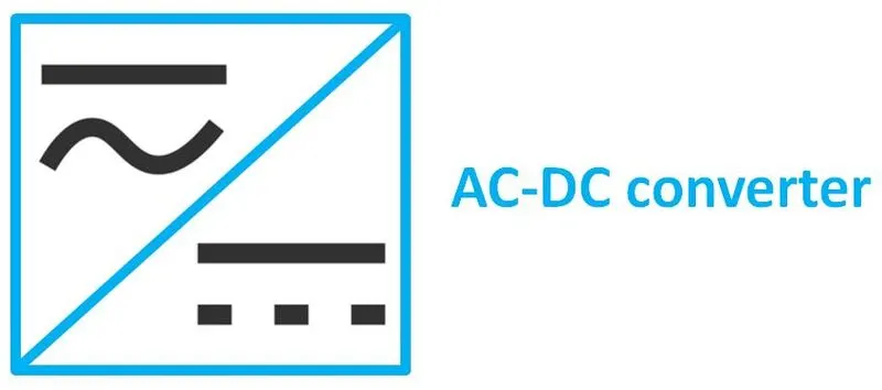
Any storage device that stores electricity for long time only in the form of DC. Electric vehicles and plug in hybrid vehicles can be charged using house hold power supply utilities or power grids generally in the form of AC voltage, in order to store it in a energy storage system in a car it need to be converted in to DC for which an AC-DC converters in other term called as ‘rectifiers’ are being employed in the vehicles.
In both Electric and Hybrid electric vehicle other than the charging grids there is some other mean to harness energy during the operation of the vehicle like regenerative braking; this short term power generation is being done by the generator and stored in ESS like super capacitor or battery which requires a rectifier to convert the AC output from the generator to DC as input to the battery.
Specifically in Hybrid electric vehicle part of the energy from the engine other than which require for the vehicle power demand is being used to charge the batteries that also requires an AC-DC convert to be in place.
In order to aid the above 3 scenario a common AC-DC converter can be employed for the ESS. - DC-DC converter
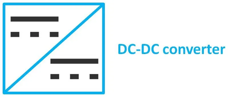
The battery or other ESS stores electric energy in the form of DC which need to be supplied to the load and other auxiliary components responsible for the operation and control of the vehicle, these appliances generally operates under different ratings. For example the battery supply voltage can be of 100V while the headlight and wind shield wipers operate at 12V rated supply, control systems operates at 5V and power systems operates at 120V. To meet this kind of different power rating needs a DC-DC converters are being employed.
In Electric and Hybrid electric vehicle 2 types of DC-DC converters are used widely as
Buck converter or Step down converter: A buck converter is a step down converter which converts the constant state power supply from the battery a magnitude lesser than that of the input. In electric or hybrid electric vehicles uses the battery with more potential difference than that of the conventional vehicle battery, but the other auxiliary and controller components in the vehicle operates at certainly at a low range supply, for this the higher potential from the battery is stepped down to a lower range by switching On and Off the MOSFET as per the duty cycle is called step down conversion.Boost or Step up converter: In electric vehicle under certain circumstance or in constant basis the power system would demand the input potential higher than that of the battery. To meet this need a DC-DC Boost converter is being used. This works by the same principle as like the buck converter that t uses a PWM for the specified duty cycle to turn On and Off the MOSEFT to achieve the magnitude of voltage that the vehicle power system requires.
- DC-AC converter (Inverter)
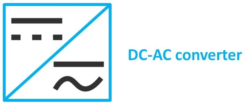
There are different types of electric drives being used in electric vehicle that includes a type induction motor. As induction motor works based on elector magnetic induction chasing the rotating magnetic field which requires the motors stator polarity change to achieve rotating magnetic field which requires AC current to the job, but the electric energy storage system in all the vehicle provides only the DC source which cannot be directly used for the induction motor, for that purpose a DC-AC converter is being employed.
This DC-AC converter converts the DC voltage in to AC sinusoidal wave patter by using switching devises with the corresponding duty ratio with the aid of programmed module. The generated waveform is not a true AC; it was formed using duty cycle to resemble the AC pattern which requires for the functioning of AC induction motor. - AC-AC converter (Cyclo converter)
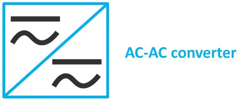
The AC-AC converters not find a wide range of application in electric vehicle but it is getting used for some specific application. While the series Hybrid electric vehicle where the generator driven by the engine directly powers up the electric motor uses AC-AC converter to attain variable speed requirement of the vehicle, this can be seen as an assist to the throttle or sometimes can be a throttle itself. This converter is also called as Cyclo converter which reduces or increases the frequency of the input AC supply to the range desirable to operate the vehicle.
Objective-2
Find the steady state speed of an electric vehicle at 70% duty cycle under given parameters
Rated armature current= 400 A
Ra= 0.5Ω, KΦ= 0.7 Volt second
Chopper Switching frequency= 400 Hz
The vehicle speed-torque characteristics are given by the below equation
Tv = 24.7 + (0.0051)
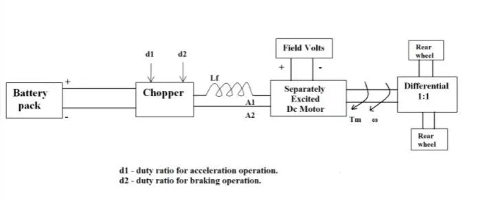
We are given with the rated armature voltage of 72V, we also know the duty cycle as 70%.
Now the armature voltage, Va = 72*0.7 = 50.4V
The vehicle Speed-Torque characteristic equation is given by the equation
`Tv = 24.7 + (0.0051)ω^2` equ (1)
Torque can also given by
`T=(V-Kφ .ω)((Kφ)/(Ra ))`
By plugging in the torque equation (2) in equation (1) we will get the quadratic equation as below
Solving for the quadratic equation using the quadratic formula, `X= (-b±√(b^2 )-4ac)/(2a )`
for positive solution we can get the speed of the motor ω = 38.915 rad/sec
By considering the reduction ratio on the vehicle wheel as 1:1 we can conclude the motor speed as the vehicle wheel speed.
Converting wheel speed of EV in to RPM we get Speed = 371.61RPM.
Since there are no data given for vehicle wheel radius so we conclude the EV speed in RPM rather than Kmph.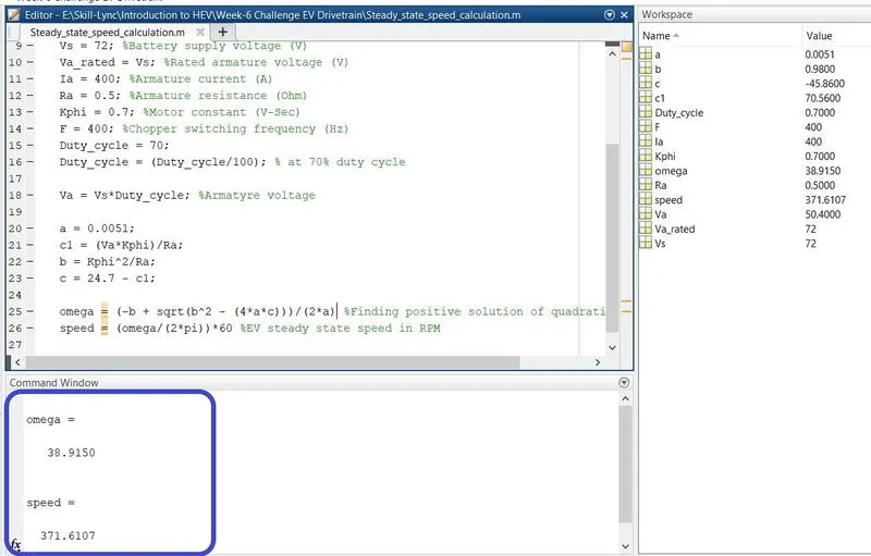
Code:
The MATLAB code for the EV steady state speed calculation is given below
clear all
close all
clc


%To find the steady state speed of the vehicle at 70% duty cycle

%Given parameters
Vs = 72; %Battery supply voltage (V)
Va_rated = Vs; %Rated armature voltage (V)
Ia = 400; %Armature current (A)
Ra = 0.5; %Armature resistance (Ohm)
Kphi = 0.7; %Motor constant (V-Sec)
F = 400; %Chopper switching frequency (Hz)
Duty_cycle = 70;
Duty_cycle = (Duty_cycle/100); % at 70% duty cycle

Va = Vs*Duty_cycle; %Armature voltage

a = 0.0051;
c1 = (Va*Kphi)/Ra;
b = Kphi^2/Ra;
c = 24.7 - c1;

omega = (-b + sqrt(b^2 - (4*a*c)))/(2*a) %Finding positive solution of quadratic equation
speed = (omega/(2*pi))*60 %EV steady state speed in RPM
The same can also be downloaded from the link provided below.
https://drive.google.com/file/d/1Qo_UNWc3ohxeP2qiGN4vLxXW3c1evW_X/view?usp=sharing
Objective-3
Develop a mathematical model of a DC Motor for the below equation using Simulink.
`ω= V/(Kφ)-R_a/(Kφ)^2 T`
We have given with the speed equation of a DC motor, to proceed this further we have taken the below parameters as assumption for this exercise
Armature voltage, Va = 72V
Armature resistance, Ra = 0.7Ω
Motor constant, K = 0.7V-S
Motor torque, T = 42.6539 N-m
The above parameters have been assigned to the appropriate variables in the simulink model workspace.
The assigned variables were then called using constant block and connecting with basic arithmetic operator block the corresponding output of DC motor speed was obtained as 59.33 rad/sec.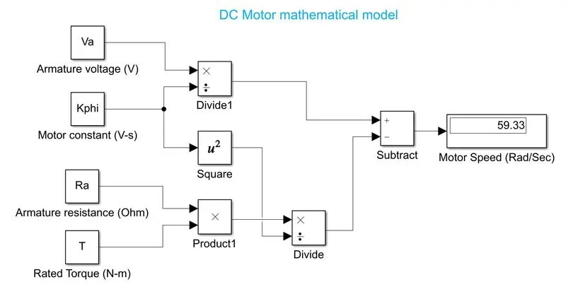
Result:
The download link for the above simulink model has been provided in the below link
https://drive.google.com/file/d/183lJNCeyjMVy_K080omDXGNiCglARUnQ/view?usp=sharing
Objective-4
Refer to the blog on below topic:
Induction Versus DC brushless motors by Wally Rippel, Tesla
Explain in brief about author’s perspective.
From the given article it was understood that the author intended to do a technological comparison between the brushless DC motor and Induction motor and how the induction motor can be tuned to compete with the DC motors for electric vehicle applications.
Some of the key points from the article has been put together in the below table.
|
Parameter |
Brushless DC motor |
Induction motor |
|
Source |
DC voltage source |
AC voltage source |
|
Rotor type |
Permanent magnet rotor |
Laminated stamped iron sheet with buried steel squirrel cage |
|
Motor principle |
Electromagnetic interaction between stator and rotor |
Electromagnetic induction due to rotating magnetic field |
|
Compatibility to utility power |
No compatible for conventional utility power since an inverter is required to produce desirable amount of starting torque. |
Compatible for conventional utility power source with good starting torque. No inverters are required. |
|
Compatibility to DC source |
Compatible to DC source with switching device for reversing the polarity of the stator pole for every 180° rotation of the rotor. |
Not compatible for DC source since rotating magnetic field cannot be achieved. With the help of inverter the DC source can be rectified in to pseudo AC wave form thus make the induction motor to produce torque. |
|
Feedback device |
Requires position sensor to aid the control system to determine the stator poles polarity change with respect to the commanded torque and speed. |
Requires a speed sensor for the controller to adjust the error between the commanded and producing torque and speed to keep the motor at desired speed variations. |
|
Peak point energy efficiency |
DC brushless motor provides more efficiency since the heat generated from the brushless DC motor is low when compared to induction motor. |
In induction motor the peak point efficiency is low when compared to brushless DC motor, as the induction motor produces more heat due to the back emf produced. |
|
Power loss |
Due to the permanent magnet rotor construction it is difficult to change the magnetic field strength during different load conditions. Which leads to eddy current and hysteresis loss. |
In induction motor the magnetic field strength is being produced in the stator and speed control being done using the AC source frequency it is possible to adjust the magnetic field strength based on speed-torque condition. This made the induction motor posses low power loss. |
|
Size to efficiency ratio |
The increase in size of the DC motor also increase the magnetic losses this decreases the efficiency. |
Increase in size of the motor does not necessarily increase the magnetic loss since it is being controlled in stator so the efficiency will not go down as like in DC motor. |
|
Cost |
Manufacturing and service cost of DC brushless motors are high as ferromagnetic materials are costlier and is difficult to protect as it cannot be de-excited for maintenance. |
Induction motor does not used permanent magnet which puts the motor manufacturing cost lesser than that of DC brushless motor but the induction motor is difficult to control over the entire speed-torque range thus adds development cost to the motor but not recurring maintenance expenses. |
Conclusion:
Thus the EV drive train system has been studied and understood and the given 4 objectives were completed.