Week-6 Challenge: EV Drivetrain
1.
aim: to find Which types of power converter circuits are employed in electric and hybrid electric vehicle
explanation:
power converters used in EV :
ev vehicles are those which are run by the battery source by using the traction motors or by using tye conventional fuel converters
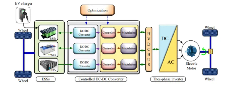
power converters used in HEV:
hev vehicles are those which uses both the conventional and battery fuel in order to run the vehicle.in this case power control techniques vary from the ev vehicle .
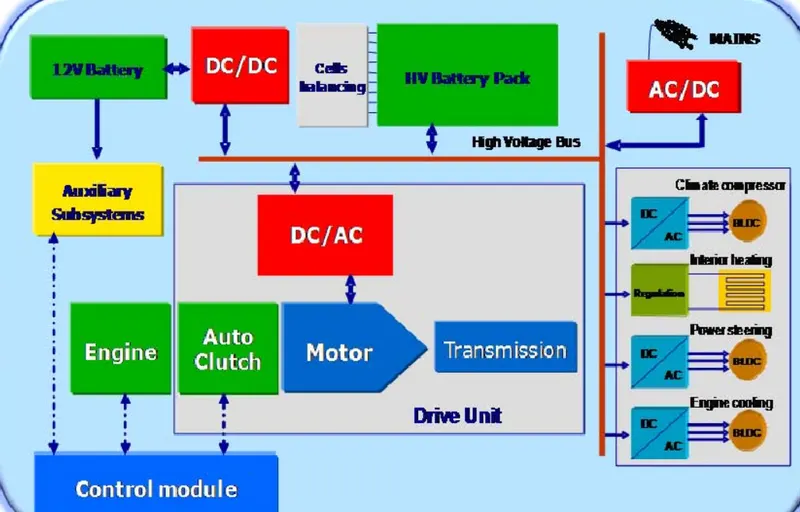
based on the topology classification these converters are classified in to two types they are
1.isolated converters
2.non isolated converters
isolated converters:
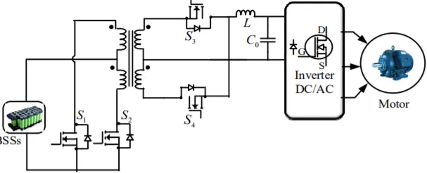
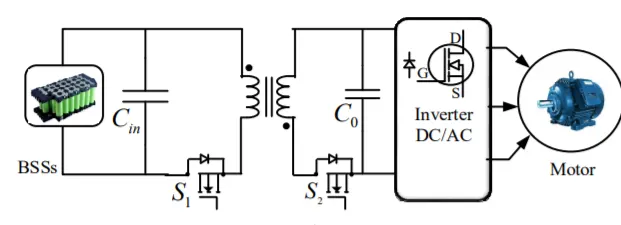
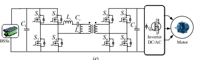
The isolated bidirectional converter is designed using three primary phases, includingDC/AC/DC. A high-frequencytransformer (HFT) is utilized to lift the input voltage athigher values through the utilization of the intermediate AC stage. The HFT is responsible for providing galvanic isolation, leading to high voltage gain. The various isolatedconverters for EV applications are presented in the following sections
examples of isolated converters:
1.push pull converter
2.flyback converter
3.resonat converter
Non isolated converters:
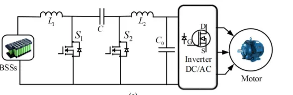
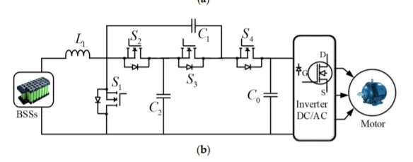
Non-isolated bidirectional DC-DC converters includes conventional DC-DC converters and interleaved DC-DC converters. Among them, conventional DC-DC converters are commonly employed due to their low cost, simple topology and easy control technique. The interleaved DC-DC converters have become popular due to their improvedperformance and efficiency
examples of non isolated converters:
1.cuk converter
2.switched capsitor bidirectional capasitor:
2.
aim:
to find the steady state speed of the ev vehicle having with 72 volt battery pack with duty cycle of 70% and other parameters as stated below
explanation:
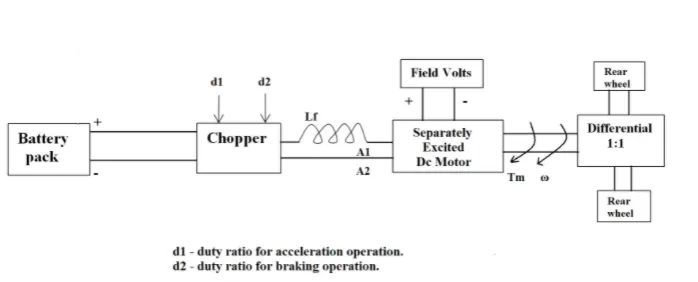
input parameters
Rated Armature voltage= 72 V
Rated armature current= 400 A
Ra= 0.5Ω, KΦ= 0.7 Volt second
Chopper Switching frequency= 400 Hz
duty cycle =70% =0.7
actaual voltage = rated voltage* duty cycle
= 0.7*72
= 52.04
we know that relation between torque and speed is
`omega =((Va)/(K*phi)) -((Ra)/(Kphi)^2)*T`
we can rewrite the above equation by solving the above parameter
`T = 70.56 - 0.98omega` ---1
given equation is
`Tv= 24.7 + 0.0051 (omega)^2`---2
compare the above two equations and obtain the values of `omega`
`24.7 + 0.0051omega^2 = 70.56-0.98omega`
`0.0051omega^2 + 0.98 omega-45.86 =0`
`omega`= 38.915 rad/sec , -231 rad/sec
from the above calculations speed of the ev vehicle is 371 RPM
3.
aim:
to Develop a mathematical model of a DC Motor for the below equation using Simulink
ω"> ωω= V/Kϕ">ϕϕ -Ra/Kϕ">ϕϕ^2 .T
explanation:
simulink block diagram:
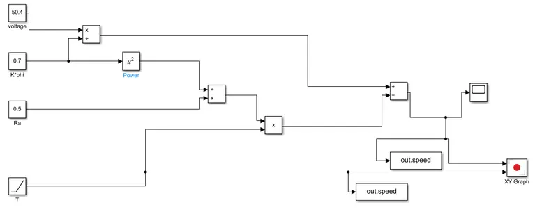
blocks used:
1.constant block: used to store a constant value

2. power block: which is used to find the square of the value

3.ramp: used to vary the value by a given slope provided

4.scope: this block is used to plot the value provided with the time

5.xy graph : this plot block is different from the scope this is used to plot grapg between to parameters

result:
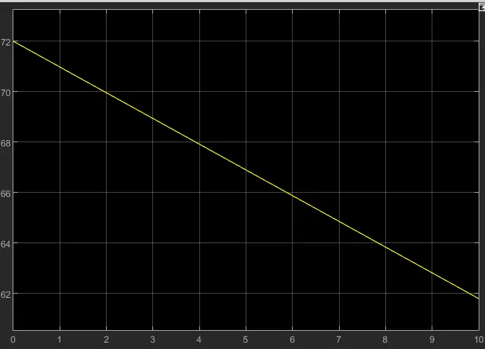
steps to follow:
1.take the constant blocks to set the values of voltage, k phi,resistance values
2.use ramp block to vary the torque to a required slope
3.connect the blocks shown as above using power , multiply and addtition block to get the equation done
4.connect the final signel to scope block to view the graph plotted
4.
Wally Rippel is a long-time proponent of electric vehicles. Prior to joining Tesla Motors, he was an engineer at AeroVironment, where he helped develop the EV1 for General Motors and was featured in the documentary movie, Who Killed the Electric Car? Wally has also worked for the Jet Propulsion Laboratory on electric vehicle battery research, among other projects. In 1968, as a Caltech undergraduate student, he built an electric car (a converted 1958 Volkswagen microbus) and won the Great Transcontinental Electric Car Race against MIT.
we have a different classifications in the models of the ic engines unlike all the engines only a single model will be put in to the production based on the prefernces such as price a performace this trick applies to the EV vehicles too
lead acid batteries and dc brushed motors are the replaced by the lithum batteries and dc brushless and induction motors. these are the motor which are going to last long due to their consistent good performace
induction motors:
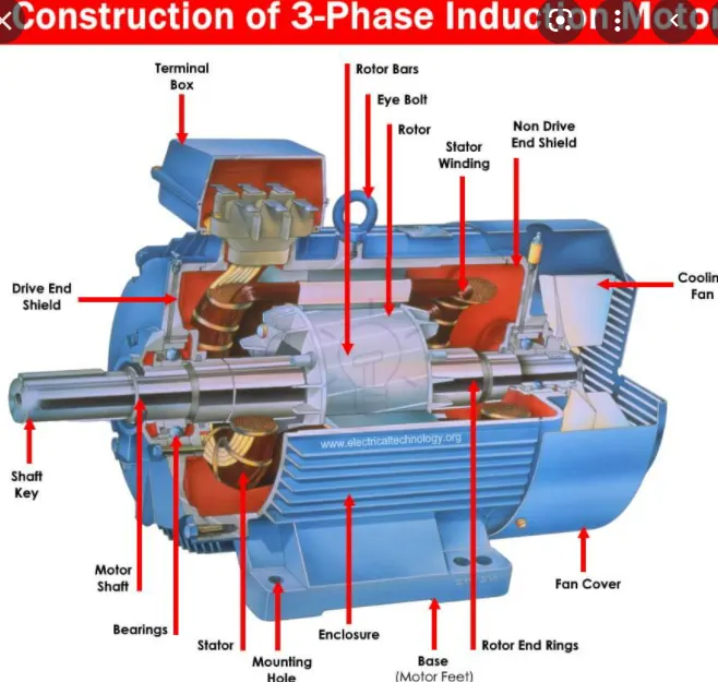
this induction motor consists of a stator and rotor.it is a three phase induction motar stator is eqipped with distributed windings this motor is somwhat similar to the dc brushless motor in the rotor construction
dc brushless motors:
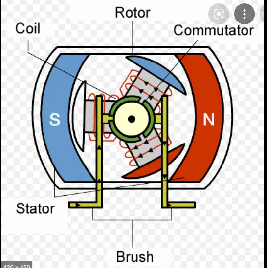
this motor consists of the two permanent magnets that generate dc magnetic field.this motor also consists of two main componets such as rotor and stator .construction of stator differs from the induction motor
advantages of these motors:
induction motors:
1.it doesnt need any magnets
2.magnetic felid is adjustable
3.motor can start with or without the inverter
4.it reduces magnetic and conduction losses
5.efficient for high performance
DC brushless motars:
1.better cooling capsity than induction motor.
2.it can operate at unity power factor
3.peak point energy efficiency is higher than that of induction motor
4.low heat generation during the working conditions.
disadvantages of motors:
induction motors:
1.it cannot operate at dc power supply it requires ac power
2.these are constant speed machines
3.limited starting torque
DC brushless motars:
1. magnetic losses increase with size of motor
2.Part load efficiency drops with size of motor
3. high cost of the permanet magnets
conclusion:
the author draws a contrast between the induction and brushless motor in the various aspects of the working condtions .these motors are mostly used in the production of the ev vehicles .he closely stuided the properties of these motors. these are the two most efficient motors which are replacing the dc brushed motors .he also predicts that these motors are going to last long in the near future.