Week-6 Challenge: EV Drivetrain
Week-6 Challenge: EV Drivetrain
1. Which types of power converter circuits are employed in electric and hybrid electric vehicle?
Answer:-
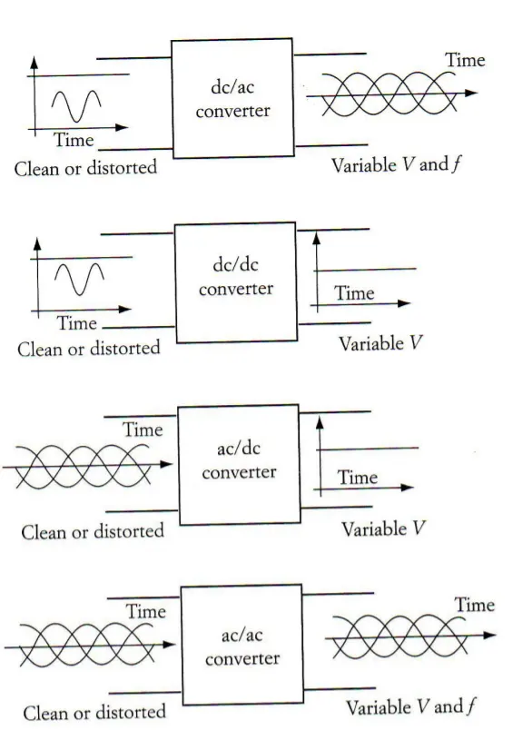
- AC to DC converter, or 'rectifier'
- DC to AC converter, or 'inverter'
- AC to AC frequency converter, or 'transformer'
- DC to DC voltage, or 'current converter'
- AC to DC Converters- An AC to DC converter circuit can convert AC
voltage into a DC voltage. The DC output voltage can be controlled by
varying the firing angle of the thyristors. The AC input voltage could be
a single phase or three phase. - AC to AC Converters - This converters can convert from a fixed ac
input voltage into variable AC output voltage. The output voltage is
controlled by varying firing angle of TRIAC. These type converters are
known as AC voltage regulator. - DC to DC Converters - These converters can converter a fixed DC input
voltage into variable DC voltage or vice versa. The DC output voltage is controlled by varying of duty cycle
Power converter used in Hybrid Electric Vehicle-
Power electronics is one of the enabling technologies propelling the shift from conventional gasoline/diesel engine‐powered vehicles to electric, hybrid, and fuel cell vehicles. This chapter discusses the power electronics used in HEVs and PHEVs. However, the focus of the chapter is on the unique aspects of power electronics in HEVs and PHEVs.
To explain the types of power electronics circuits used in an HEV, we use the configuration of a typical series HEV powertrain as shown in Figure 9.1. In this configuration, the internal combustion engine (ICE) drives a three‐phase permanent magnet synchronous generator, whose output is a three‐phase voltage with variable frequency and variable voltage. This output needs to be rectified to DC.
Figure 9.1 Power electronics converters used in a series HEV.
The front wheels are driven by an induction motor which needs to be controlled by a voltage source inverter (VSI) or a current source inverter (CSI). An energy storage system is connected to the DC bus, between the generator/rectifier output and the inverter. However, there is a bidirectional DC–DC converter that manages the charge/discharge of the battery, as well as controlling the DC bus voltage.
Power converter used in Electric Vehicle-
- An Electric Vehicle is a vehicle that uses a combination of different energy sources, Fuel Cells (FCs),Batteries and Supercapacitors (SCs) to power an electric drive system as shown in Fig. 1.
- In EV the main energy source is assisted by one or more energy storage devices. Thereby the system cost, mass, and volume can be decreased, and a significant better performance can be obtained.
- Two often used energy storage devices are batteries and SCS. They can be connected to the fuel cell stack in many ways. A simple configuration is to directly connect two devices in parallel, (FC/battery, FC/SC, or battery/SC). However, in this way the power drawn from each device cannot be controlled, but is passively determined by the impedance of the devices.
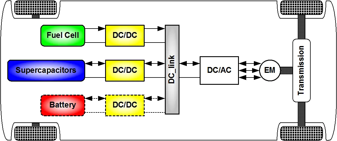
Figure 1.Electric vehicle drive system.
2. An Electric Vehicle's powertrain with 72V battery pack in shown in the diagram below. The duty ratio for acceleration operation is 'd1' and for the braking operation the duty ratio is 'd2'.
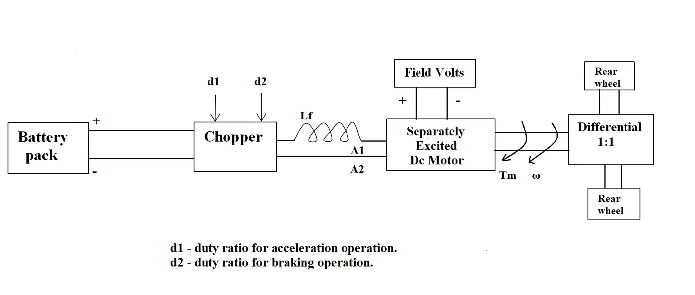
The other parameters of the electric vehicle is given below,
Motor and Controller Parameters:
Rated Armature voltage= 72 V
Rated armature current= 400 A
Ra= 0.5Ω, KΦ= 0.7 Volt second
Chopper Switching frequency= 400 Hz
The vehicle speed-torque characteristics are given by the below equation

What is EV steady state speed if duty cycle is 70%?
Answer:-
Given-
- Bttery pack voltage=72v
-
Rated Armature voltage= 72 V
-
Rated armature current= 400A
-
Armature resistance Ra= 0.5Ω
-
Motor constant KΦ= 0.7 Volt second
-
Chopper Switching frequency= 400 Hz
- Duty cycle =70%
- Vehicle Torque-speed chara. equation `Tv=24.7+(0.0051)omega^2`
- Tm:Tv
Calculation-
Duty cycle =70%=0.7
Average Voltage Vo=Va*duty cycle
Vo=72*0.7
=50.4
`omega=(Vo)/(Kphi)-(Ra)/(Kphi^2)*Tm`
`omega=50.4/0.7-0.5/0.7^2*Tm`
`omega=72-1.0204*Tm`
`Tm=70.56-0.98omega`
given is Tm:Tv
`70.56-0.98omega=24.7+0.0051omega^2`
`0.0051omega^2-0.98omega-45.86=0`
This equation is like quadratic equation `ax^2+bx+c=0`
`x=(-b+-sqrt(b^2-4ac))/(2a)`
by solving this quadratic equation we get
`omega=38.915 and omega=-231.072`
for Speed value we take only positive value
so ω=38.915 rad/sec
Speed at rpm = 38.915*60/2*3.14
=371rpm
EV steady state speed if duty cycle is 70% is 371rpm.
3. Develop a mathematical model of a DC Motor for the below equation using Simulink.
ωω= V/Kϕϕ -Ra/Kϕϕ^2 .T
Answer:-
Speed-Torque characteristics of DC motor is
`omega=V/(Kphi)-(Ra)/(Kphi^2)*T`
Simulation Model-
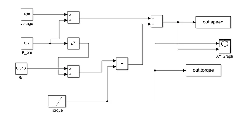
Procedure-
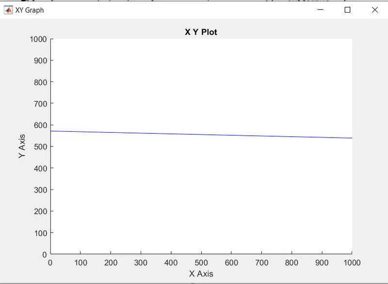
- Add the required block in model such as add,divide,product,square,constant,ramp,xyGraph,Toworkspace.
- Connect the block as per above fig.
- For voltage V constant input is given as 400V.
- K_phi is constant input is 0.7.
- Ra is constant resistance value is 0.5.
- For torque input the ramp block is given.
- To get the Speed-Torque characteristics the XY-Graph block is use.
- Run model for 300sec.
Result-
4. Refer to the blog on below topic:
Induction Versus DC brushless motors by Wally Rippel, Tesla
Explain in brief about author’s perspective.
Answer:-
- Objective of this blog is to campare the Induction Motor over the DC brushless Motor with there construction,operation,advantages,etc.
- The author Wally Rippel,Tesla which is long time proponent of electric vehicle discussed about various types of motor that came across from 1960s. Back then the motor used in electric vehicle is brushed DC motor with contactor which is no more used in this field.Nowadays its replaced with Brushless DC Motor and 3-phase induction motor
- In case of Brushless DC Motor, the rotor includes two or more permanent magnets that generate a DC magnetic field. In turn, this magnetic field enters the stator core (a core made up of thin, stacked laminations) and interacts with currents flowing within the windings to produce a torque interaction between the rotor and stator. As the rotor rotates, it is necessary that the magnitude and polarity of the stator currents be continuously varied – and in just the right way - such that the torque remains constant and the conversion of electrical to mechanical energy is optimally efficient. The device that provides this current control is called an inverter. Without it, brushless motors are useless motors.
- The 3-phase induction motor was invented by Nikola Tesla.In induction motor,the induction rotor has no magnets – just stacked steel laminations with buried peripheral conductors that form a “shorted structure.” Currents flowing in the stator windings produce a rotating magnetic field that enters the rotor. In turn, the frequency of this magnetic field as prodused by the rotor is equal to the difference between the applied electrical frequency and the rotational “frequency” of the rotor itself.
- In both motor construction the stator are same but only difference in there rotor and inverter control.
- In brushless DC motor much less heat is generated by stator and rotor and the cooling is possible therefore the peak efficiency is achived also the the motor operated at unity power factor in other hand the induction motor are operated at 85% efficiency.
- The brushless DC motor operation at peak performance is effient.The induction motor may be less efficient at peak.But the average efficiency of induction motor is better than the brushless DC motor.
- In brushless DC motor, permenant magnet is used which is more expensive.This means that induction motors will likely retain a cost advantage over PM machines.
- Induction machines are more difficult to control. The control laws are more complex and difficult to understand. Achieving stability over the entire torque-speed range and over temperature is more difficult with induction than with DC brushless.
Conclusion-
The Brushless DC motor is used for Hybrid and Plug-in-hybrid vehicle.While the induction motor is used for pure electric vehicle.