Week -2
1.Make a Simulink model of Doorbell using solenoid block with the following details:
In the above arrangement, when the switch is closed the electromagnet receives electrical power from the battery and pulls the metal arm to hit the bell producing sound.
Create a situation where the switch is closed for 2 seconds and then released. Observe the physical movement of the plunger.
Aim:
Make a Simulink model of Doorbell using solenoid block
Condition:
swich is closed for 2sec and the released
Simulink Model:
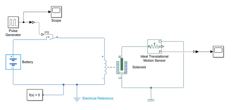
Block use for simulink model:
- Pulse Generator
- Switch
- Solenoid
- Battery
- Ideal Translational Motion Sensor
- Solver Configuration
- Mechanical Translational Reference
- Electrical Reference
- Scope
- PS-simulink converter
- Simulink-PS converter
Theory:
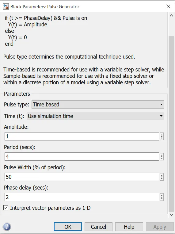
- The pulse generator is used to create square wave pulses at regular intervals of time.The block parameter as shown below
- The switch block used is controlled by external physical signal.If the external signal is greater than the thersold parameter then the switch is closed,otherwise switch is open.
- The positive terminal of switch is connected to battery and the negative terminal is connected to electrical reference.
- The solenoid block is connected with battery and switch.
- C port is connected with mechanical reference and R port connected with ideal translational sensor.
- Scope is connected with pulse generator and ideal translational sensor to get the input and output signal.
- PS-simulink converter is used to convert to physical signal to simulink signal.
- Solver configuration: Each physical network represented by a connected Simscape block diagram requires solver settings information for simulation. The Solver Configuration block specifies the solver parameters that your model needs before you can begin simulation.
Results:
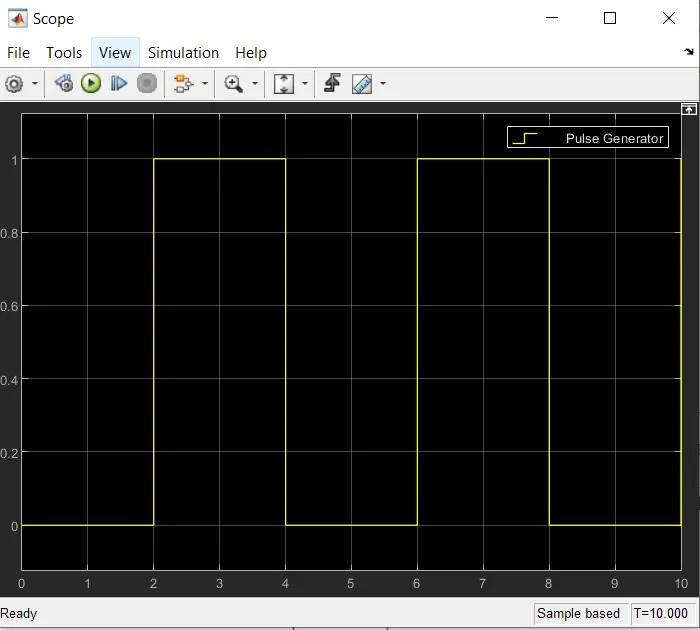
INPUT:
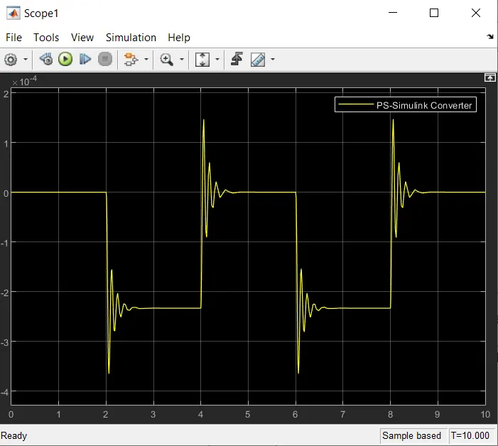
OUTPUT:
Conclusion:
The simulation was run for 10sec and the result obtained is shown above.It can be observed that at each 2sec interval the bell is ringing.
2. Use a thermistor to sense the temperature of a heater & turn on or turn off the fan as per the below conditions:
Temperature source: 20 °C from 0 to 10 seconds, 27 °C from 10 to 30 seconds, 23 °C from 30 to 50 seconds Fan conditions: ON if the temperature above 25 °C, OFF otherwise
Simulink Model:
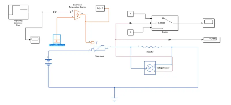
Block use for simulink Model
- Repeating Sequence Stair
- Controlled Temperature Source
- Thermistor
- Voltage Sensor
- Battery
- Resistor
- Thermal Reference
- Electrical Reference
- Switch
- Solver connfiguration
- Display
- Scope
Theory:
- A Repeating Sequence Stair is given as input to the thermistor through a controlled temperature source.The definite of Repeating Sequence Stair block is given below.
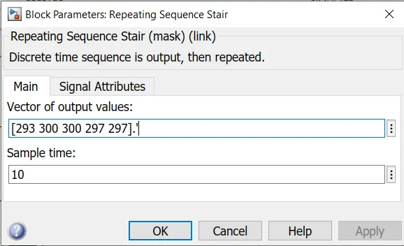
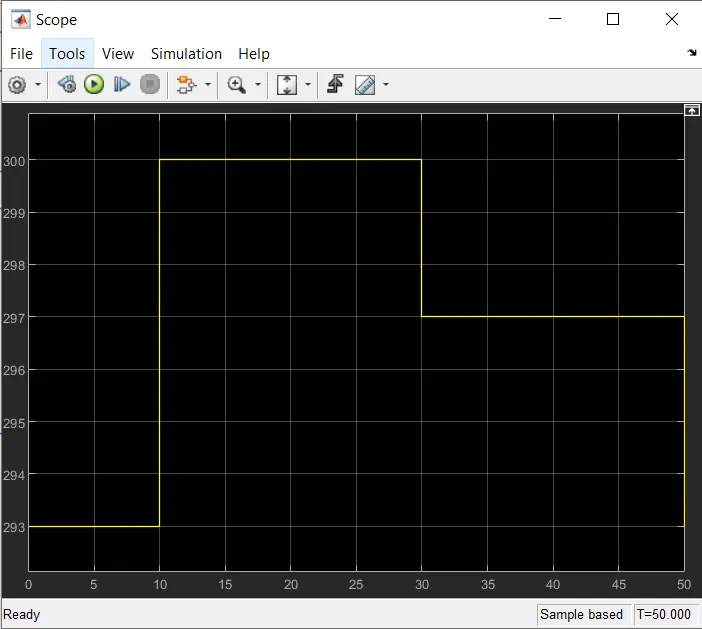
- The sample time is taken as 10sec and the simulation time is take as 50sec because there are 5 temperature condition given for each 10sec interval of time i.e [293, 300, 300, 297, 297]
- Battery and a resistor is connected in the thermistor circuit.
- The voltage sensor was given across the resistor to measure the voltage chande during the different temperature inputs.
- The resistance of this resistor can be set to any value,but it should not be changed onces the thersold voltage is found.
- The two different constant block given to this switch block
- If the simulation run at first time then the display block shows the thersold voltage value.After that this thersold value is putting into the switch block.
- Then once again the simulation is run and we get the output signal.
Result:
INPUT signal:
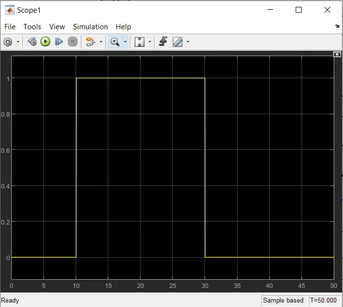
OUTPUT signal:
Conclusion:
The simulation was run for 50sec and the result obtained is shown above.It can be observed that whenever the temperature goes above the 25 °C i.e. 298K the fan will be turn ON similarly if the temperature goes below the 25 °C i.e. 298K the fan will be turn OFF.