Week - 4
- Implement control logic of a “washing machine” using Stateflow as per given sequence:
- If the power supply is available, the system gets activated
- If the Water supply is not available, stop the process & indicate through LED
- Soaking time should be 200s followed by Washing time of 100s.
- Then rinsing happens for next 20s & dryer runs for 50s
After all the processes have completed turn on the finished LED
Ans:
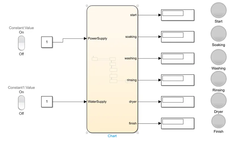
Simulation Model:
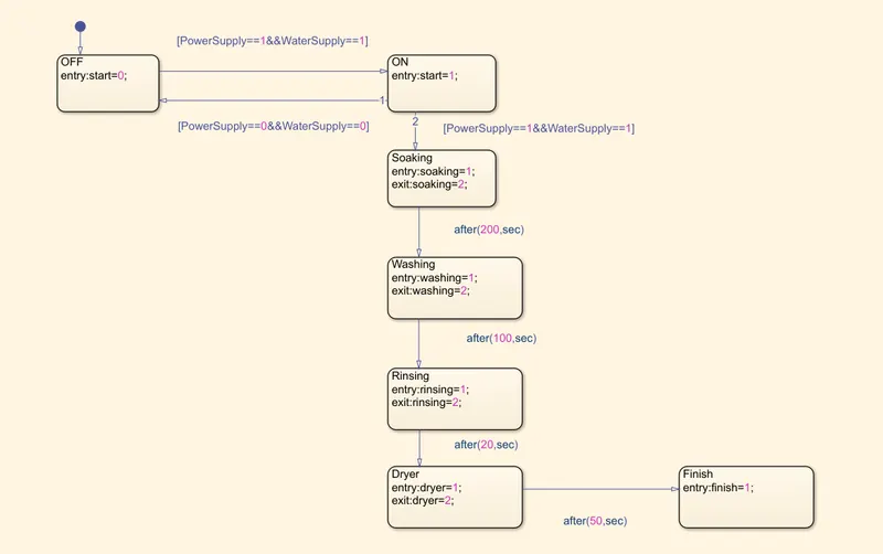
StateFlow Chart:
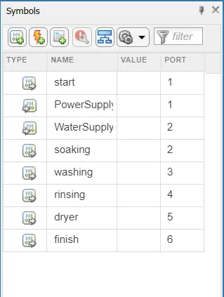
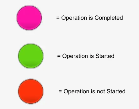
Symbols Lane:
Theory:
- In this simulation,Power supply and Water supply are two input singnal.
- In first two chart as shown in stateflow,the condition is given such as the system will run only on both the input signal is available.
- If any one from both power supply and water supply is not present then the system will not started.
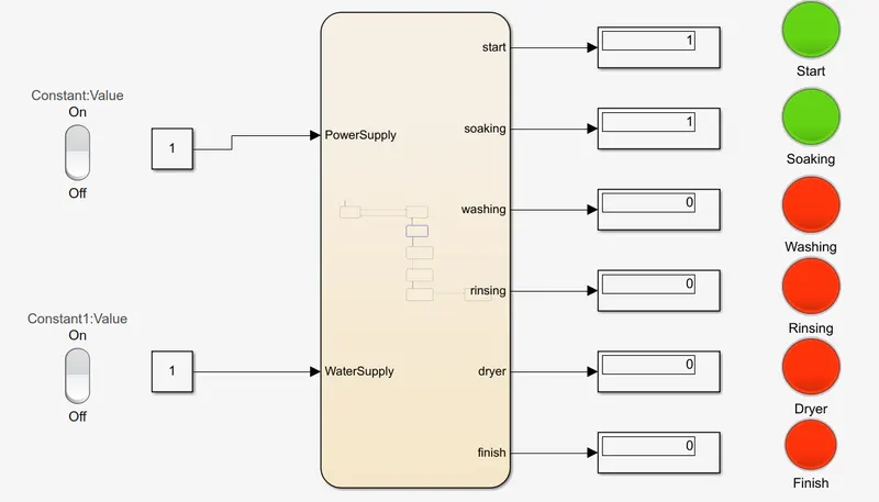
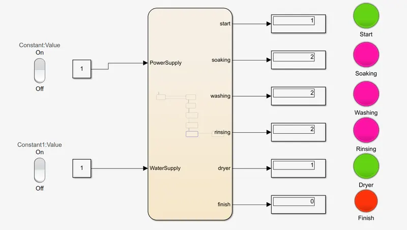
- As per the given condition,the soaking will started for that the lamp indicate the Green signal.The soaking is done for 200sec after that the lamp indicate Pink signal which means soaking is done.
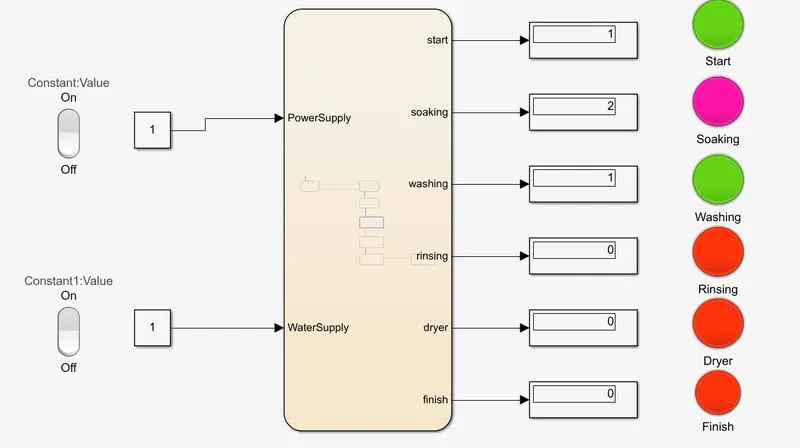
- After soaking,The washing get started and the lamp shows Green signal and after 100sec the washing is completed and lamp shows Pink signal.
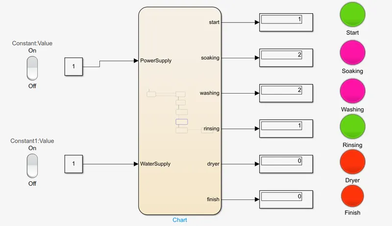
- Similarly,after washing Rinsing is started and same lamp indication is done.Rinsing last for next 20sec.After rinsing the dryer is run for next 50sec.
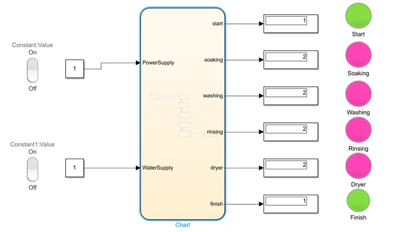
- After dryer which is run for 50sec then the operation is completed and the system is finish and finish lamp indicated Green signal.
Simulation Run Model:
1.Operation and Soaking start
2.Washing Start
3.Rinsing Start
4.Dryer Start
5.Operation is Finish
2. Make a Simulink chart for the “Gear shift” logic as per below conditions:
Speed Range(kmph) Gear
0 to 15 1
16 to 25 2
26 to 40 3
41 to 60 4
Above 61 5
Give speed input while the simulation is running & display the gear number.
Ans:
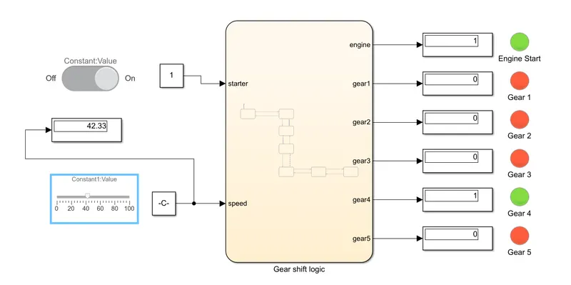
Simulation Model:
StateFlow Chart:
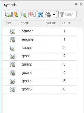
Symbols Lane:
Theory:
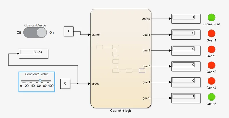
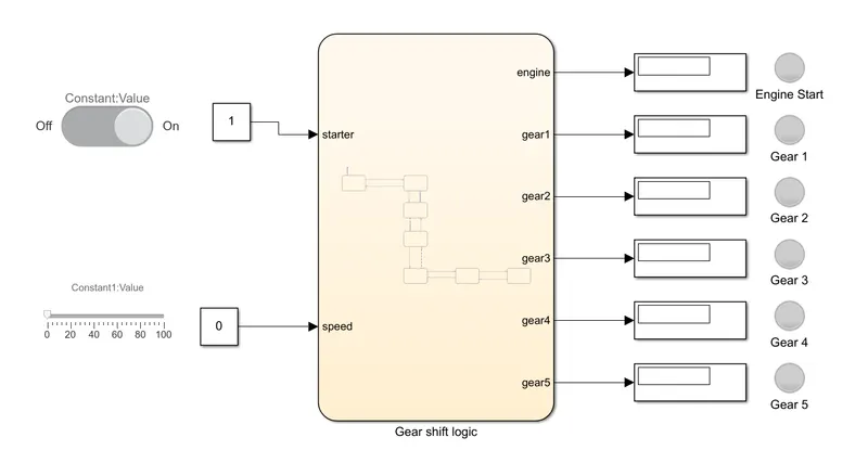
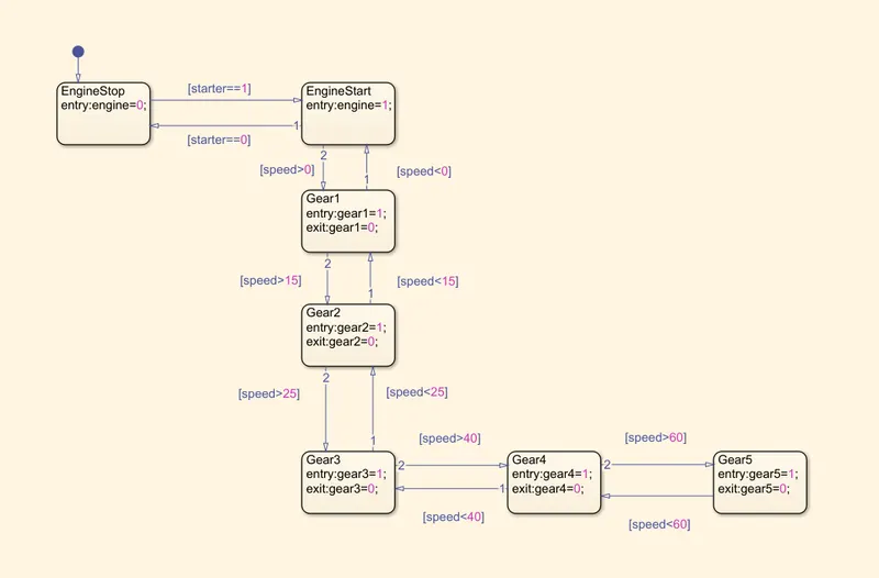
- In this simulation,the condition is define as if the starter is ON then only the system will run otherwise the gear system is not activated.
- The slider block is use for variable speed output and this slider is connected with constant block.Similarly slider switch is use for ON&OFF operation of starter.
- As per the given condition the different gear is difine for the different speed range
-
Speed Range(kmph) Gear
0 to 15 1
16 to 25 2
26 to 40 3
41 to 60 4
Above 61 5
- for example,if the speed is goes above 40 then lamp which is connected with Gear 4 is blow Green and other lanp is shows Red colour.
- The operation of different gear for different speed is shown below.
Simulation Run Model:
1.Engine Start and Gear 1
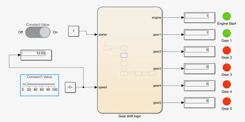
2.Gear 2
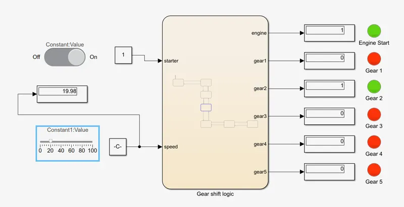
3.Gear 3
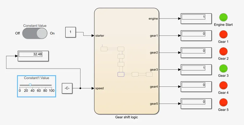
4.Gear 4
5.Gear 5