Week-6 Challenge: EV Drivetrain
- Aim:
- Which types of power converter circuits are employed in electric and hybrid electric vehicle?
- An Electric Vehicle's powertrain with 72V battery pack in shown in the diagram below. The duty ratio for acceleration operation is 'd1' and for the braking operation the duty ratio is 'd2'.
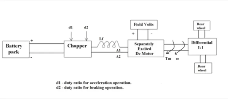
The other parameters of the electric vehicle is given below, Motor and Controller Parameters:
Rated Armature voltage= 72 V 0
Rated armature current= 400 A
Ra= 0.5Ω, KΦ= 0.7 Volt second
Chopper Switching frequency= 400 Hz
The vehicle speed-torque characteristics are given by the below equation
What is EV steady state speed if duty cycle is 70%?
- Develop a mathematical model of a DC Motor for the below equation using Simulink. ω = V/K ϕ -Ra/K ϕ ^2 .T
- Refer to the blog on below topic: Induction Versus DC brushless motors by Wally Rippel, Tesla Explain in brief about author’s perspective.
Solution 1:
The power converter circuits are employed in electric and hybrid electric vehicles. There are three major power electronic units in the general configurations.
- DC-AC inverter
- DC-DC converter
- AC-DC Rectifier
DC-AC inverter:
The supply converter from a Direct Current supply to the alternating Current supply, from a Battery to the Ac supply . This type of converter is referred to as an 'inverter and is widely used in homes and in EV/HEVs.Using an electronic switch, which is basically a set of semiconductor transistors for example IGBTS, MOSFETs, which are controlled by a controller to either be in an open or closed position to direct the flow of current in a circuit. In the case of EVs and HEVs, the battery pack will supply its power to the inverter. The inverter contains a transformer which consists of a primary and secondary winding. The current from the battery is first supplied to the primary winding where the electronic switches will repeatedly reverse the direction of the current to create an AC waveform. This current will return back the way it came from. The AC current in the primary winding will induce an AC current in the secondary winding which then supplies this current to an AC load example, the AC traction motor.
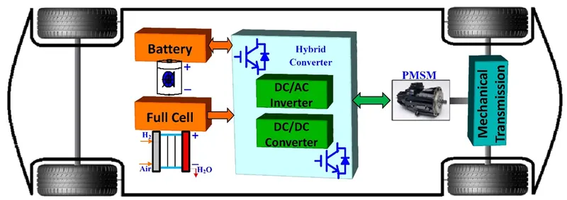
DC-DC converter:
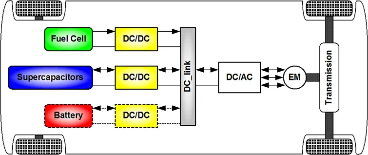
DC-DC converters can be used to interface the elements in the electric power train by boosting or chopping the voltage levels. By introducing DC/DC converters one can chose the voltage variation of the devices and the power of each device can be controlled. The different configurations of EV power supply show that at least one DC/DC converter is necessary to interface the Battery or the Supercapacitors module to the DC-link. The amount of power flow between the input and the output can be controlled by adjusting the duty cycle. his type of converter is similar to a transformer in that it can change the voltage from its current level to another level. It can take an input supply of voltage and increase it or do the exact opposite and decrease it similar to a step up or step down transfomer. This kind of a converter is called a 'chopper. The purpose of using this type of converter is to provide the necessary level of power to a particular component and for the safety of the appliance and the user. If a component if suppled with too little or too much voltage, it won't operate due to lack of power or it will get damaged, so it all depends on the load requirement. It works by taking the DC supply and passing it through a switching element which converts the waveform to a square wave which is actually AC in nature. Then this AC is passed through a filter which will will turn it back in to a DC supply for use in a load. EVS, HEVs and conventional vehicles, this type of converter is used for various purposes. E.g. In the case of stepping down the voltage, the car radio may require a stepped down voltage of 12V to operate and would not need the full voltage of the car battery. In the case of stepping up the voltage, the motor of a car may require 500V to operate, but the vehicle may need more voltage than the battery pack can provide.There are 2 main types of DC to DC converters
- Buck - to step down the voltage
- Boost - to step up the voltage
AC-DC Rectifier:
The AC to Dc converter takes an AC power supply and converts it to a DC power supply. Power received at homes is 230V at a frequency of 50Hz .Many of the appliances operate on a DC supply, So as per requirements of Ac to DC converters for examples in our daily appliances are: phone charger, laptop charger etc. AC power supply has an alternating waveform which repeatedly reverses direction. An AC to DC converter will prevent the current changing direction, so that it only flows unidirectionally. In the circuit of an AC to DC converter, there is a stepdown transformer, a diode, a capacitor and a low dropout voltage (LDO) regulator. A The stepdown transformer takes the high level 230V from the mains supply and steps it down to a lower level for exampe 12 or 13V for our use, but it is still in AC form. Then, a diode or group of diodes is implemented restrict the current to flow in just one direction. In an AC waveform, there will be positive and negative peaks at each half cycle like a sine wave. The diode(s) will remove the negative parts of the waveform so that there are positive peaks only. This is called 'rectifying' and this part of the circuit is referred to as a 'rectifier! This can be a half wave, full wave or a bridge rectifier. Then, the rectified output voltage waveform is smoothened by a filter capacitor. Finally, the LDO regulator will regulate the output for our use .In the case of EVs or HEVs, the battery pack which operates with a DC power supply is charged at home or at a charging station both of which are supplied power in AC form from the electric grid. So, the chargers for these vehicles are an example of the AC to DC power converter.
Solution 2:
As per the question we have given data;
Motor and Controller Parameters:
Rated Armature voltage= 72 V
Rated armature current= 400 A
Ra= 0.5Ω, KΦ= 0.7 Volt second
Chopper Switching frequency= 400 Hz
Duty cycle=70% , Vbat = 72V
We know that as per Formula;
Ω = Vt/Kϕ -Ra/Kϕ^2 .Tt
Vt = Vbat * Duty cycle.
=72 * 0.70
Vt =50.4
Ω= (50.4/0.7) - (0.5/(0.7) 2). Tt
Tt = (72- Ω)/1.020
Tt = 70.58-0.98 Ω
Know,
Tv=24.7+0.0051 Ω2
Comparing Tv and Tt,
24.7+0.0051 Ω2 = 70.58-0.98 Ω
0.0051 Ω2+0.98 Ω-45.88 = 0
(Ω-38.92)( Ω+231.08) = 0
Ω=38.92, -231.08
By the Solutions we obtain to values as speed cannot be a negative, hence considering only the positive value
Hence EV steady state speed = 38.92 rad/sec.
Solution 3 :
- As per question mathematical model of a DC Motor for the below equation using Simulink. ω = V/K ϕ -Ra/K ϕ ^2.T .
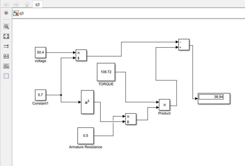
- Result :Below image shows the model for the above question having the output as 38.94 rad/sec speed in the display Simulink block
Solution 4 :
As per question we refer to the blog on below topic: Induction Versus DC brushless motors by Wally Rippel, Tesla hence; Wally Rippel’s perspectives are
The differences between the two most commonly used motor drives in the automobile industry: the DC brushless motor drive and the induction motor drive. Ripple goes in to detail about the differences in construction, working, and cost between the two drive types. However, with what he has written, he has not arrived at the conclusion that one type is better than the other. In the last lines of the opening paragraph, Ripple writes that "there is no one best engine type" and that it is all a matter of personal preference when it comes to choosing an engine. It is in this same regard that he ends the blog stating that there is still 'no winner' when it comes to motor drive selection either. In spite of both motor drive types having similarities, they also have their benefits and drawbacks.
- As per requirements the improvising technology, there has been alternatives found now and then such as lead-acid batteries, DC brush motors and contact controllers have been replaced by lithium batteries, brushless DC or induction motors and inverters.
- Though there has been various replacements, brushless DC and induction motors are playing a major role till this date. For DC Brushless drives, we are told that their construction implements 2 or more permanent magnets at the rotor to generate a DC magnetic field. It also consists of a stator core (made up of thin, stacked laminations) It also uses an inverter for the current control, meaning that it cannot run on a DC power supply as the current direction has to be changed repeatedly in to maintain a constant torque.
- For induction drives, there rotor has no magnets, but instead stacked steel laminations with buried peripheral conductors which form a 'shorted structure. It is the current in the stator Windings that generates a rotating magnetic field that interacts with the rotor. Induction motors can be used directly with power from the mains and does not require an inverter to start the drive and generate the starting torque. It has the ability to start under the mains load applied. However, DC brushless drives cannot do the same. They cannot generate a starting torque when connected to a mains power supply. They require an inverter to do this.
- The pros and cons of both brushless DC motors and induction motors are being discussed. The advantages of brushless dc motors are: much less rotor heat is generated. the peak point efficiency will only be a few % higher than an induction motor. The disadvantages are: as the machine size grows, the magnetic losses increase proportionately and part load efficiency drops. permanent magnet (PM) rotors are also difficult to handle due to very large forces that come into play when anything ferromagnetic gets close to them.
- Induction motor has some advantages: the motor has no magnets. the motor can start under no-load conditions. the disadvantages are: they cannot operate in DC. When operated with utility power, they have limited starting torque and limited running peak torque capabilities when compared to DC type machines.
- The author’s conclusion is that DC brushless drives will likely continue to dominate in the hybrid and coming plug-in hybrid markets, and that induction drives will likely maintain dominance for the high-performance pure electrics.
- Also now fact is that hardware for both of them are common that we will see induction and DC brushless live and applicable for the future era of hybrid and electric vehicles.
- Conclusion:
- From Q1: We get the information about different types power converter circuits are employed in electric and hybrid electric vehicle.
- From Q2: We get to know that the EV steady state speed is 38.92 rad/sec. if duty cycle is 70% .
- From Q3: We get to know that by developing a mathematical model of a DC Motor for the below equation using Simulink. ω = V/K ϕ -Ra/K ϕ ^2.T is EV steady state speed is 38.94 rad/sec. observed in the
- From Q4: Comparing both of the machines are common that we will see induction and DC brushless live and applicable for the future era of hybrid and electric vehicles.