Project
- Aim: To study and prepare a technical report of BAJA ALL- TERRAAIN Vehicle (ATV) under different conditions.
- Objectives: Model Properties and technical report.
- ALL TERRAIN VEHICLE:
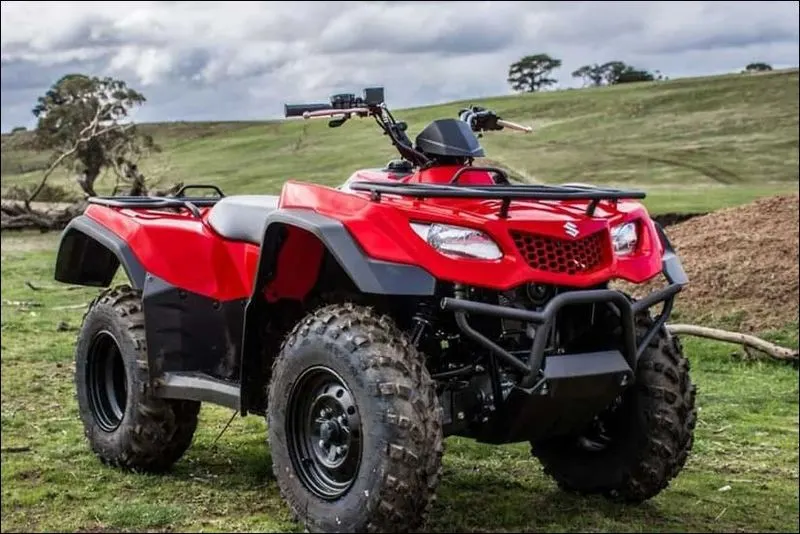
Above images shows an ALL TERRAIN VEHICLE (ATV) is a four wheel drive vehicle, as a motorized off-highway vehicle designed to travel on four low-pressure or non-pneumatic tyres, having a seat designed to be straddled by the operator and handlebars for steering control.
- Case1: Simulink Model for BAJA ATV With CVT
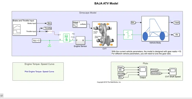
- Explanation:
- Generic Engine Block :
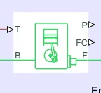 This block represents a system level model of spark-ignition and diesel engines suitable for use at initial stages of modelling when only the basic parameters are available. Optional idle speed and red line controllers are included. The throttle input signal T lies between zero and one and specifies the torque demanded from the engine as a fraction of the maximum possible torque. If the engine speed falls below the stall speed, the engine torque is blended to zero. If the engine speed exceeds the Maximum speed, the simulation stops and issues an error message. Connections F and B are mechanical rotational conserving ports associated with the engine crankshaft and engine block, respectively. Connections P and FC are physical signal output ports through which engine power and fuel consumption rate are reported.
 - Signal builder:
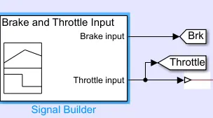 Here this block is used to build signals for Brake input and Throttle input.
 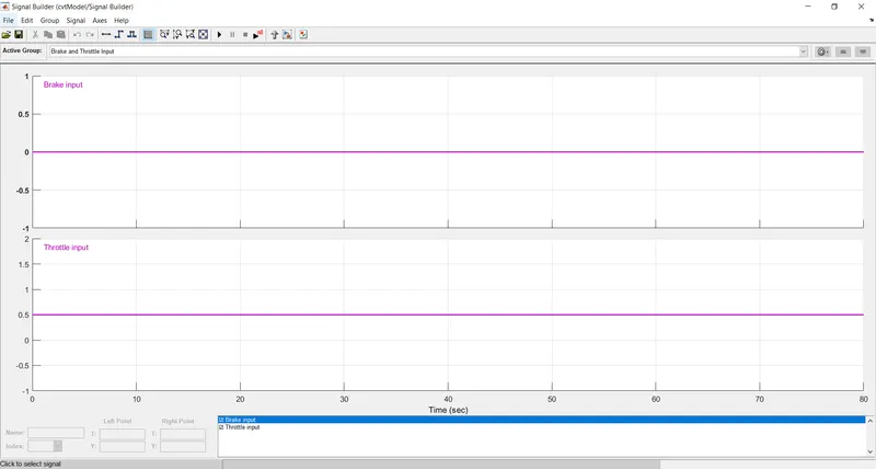 Also
Also 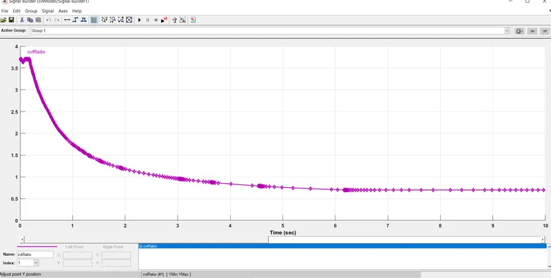
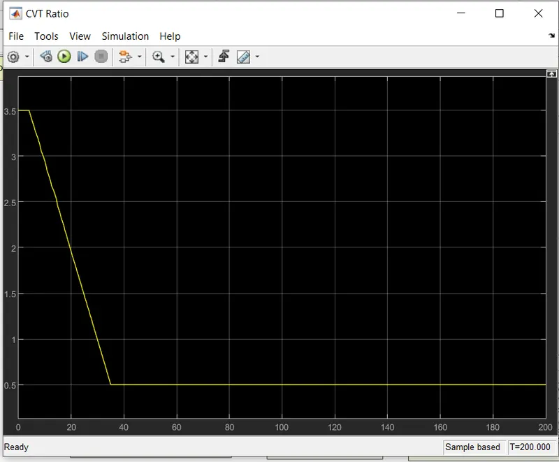
Above image showing results for the signal building Cvt Ratio.
- CVT Model Block Diagram
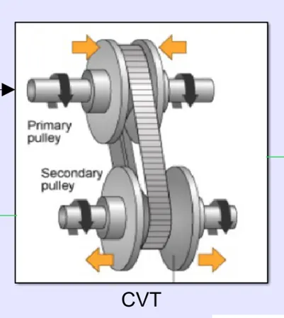
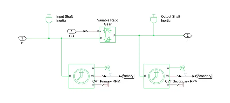
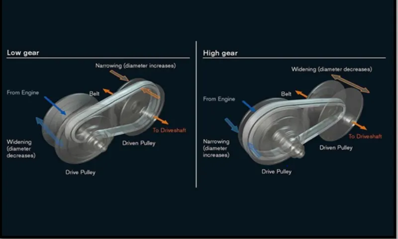
Above image represents mechanism of gears in CVT. Requirement of gears is the most important function role, the more the gears better functioning of transmission by optimizing the engine speed in a variety of conditions. Hence it is predicted low gears provides better acceleration while higher gears enhances Fuel Economy. Here CVTs differ from the traditional automatic transmission in that they donot have gears that . provides (steps) between low and high speed operations. Although the majority of them work via pair of variable – Diameter, Cone-shaped Pulleys connected by a steel or composite belts. The halves of each pulley are aligned with the pointed ends of the cones touching. These form a V- shaperd groove in which the connecting belt rides. One side of the pulley is fixed and the other is movable, actuated by a hydraulic cylinder which is used to increase and decrease the amount of space between the two sides of the pulley allowing the belt to ride lower or higher along the walls of the pulley, depending on the driving conditions, there by changing the (Gear ratio).
The block used in the CVT model are:
a.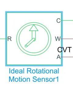 Ideal Mechanical Rotational Motion Sensor -The block represents an ideal mechanical rotational motion sensor, that is, a device that converts an across variable measured between two mechanical rotational nodes into a control signal proportional to angular velocity or angle. The sensor is ideal since it does not account for inertia, friction, delays, energy consumption, and so on. Connections R and C are mechanical rotational conserving ports and connections W and A are physical signal output ports for velocity and angular displacement, respectively. b. b.
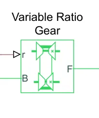 Variable Ratio Gearbox – This block represents a variable ratio gearbox such as implemented by mechanical belt CVT, electric, or hydraulic transmissions. The physical signal input r defines the ratio of input to output angular shaft velocities. Also the Connections B (base) and F (follower) are mechanical rotational conserving ports. Specify the relation between base and follower rotation directions with the Output shaft rotates parameter.
c. 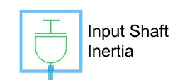 Inertia Block - The block represents an ideal mechanical rotational inertia. Which has one mechanical rotational conserving port. The block positive direction is from its port to the reference point. This means that the inertia torque is positive if the inertia is accelerated in the positive direction.
4. 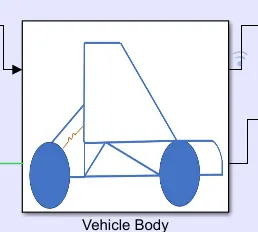 Here we have created a sub sytem for the specified vehicle body block diagram;
Simulink Block Diagram:
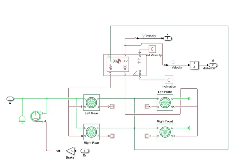
Above and below image describes about the vehicle body Consisting of blocks used for the working.
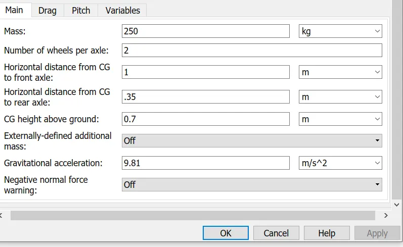
Represents a two-axle vehicle body in longitudinal motion. The block accounts for body mass, aerodynamic drag, road incline, and weight distribution between axles due to acceleration and road profile. The vehicle can have the same or a different number of wheels on each axle. Optionally include pitch and suspension dynamics or additional variable mass and inertia. The vehicle does not move vertically relative to the ground.Connection H is the mechanical translational conserving port associated with the horizontal motion of the vehicle body. The resulting traction motion developed by tires should be connected to this port. Connections V, NF, and NR are physical signal output ports for vehicle velocity and front and rear normal wheel forces, respectively. Wheel forces are considered positive if acting downwards. Connections W and beta are physical signal input ports corresponding to headwind speed and road inclination angle, respectively. If variable mass is modeled, the physical signal input ports CG and M are exposed. CG accepts a two- element vector representing the x and y distance offsets from vehicle CG to additional load mass CG. M represents the additional mass. If both variable mass and pitch dynamics are included, the physical signal port J accepts the inertia of the additional mass about its own CG.
5. Results:
Output Speed Results
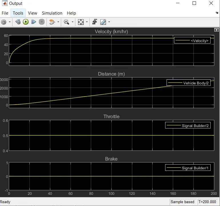
Above image shows results as the Velocity of the vehicle is (V= 55km/hr).
CVT Shaft Rpm Results -
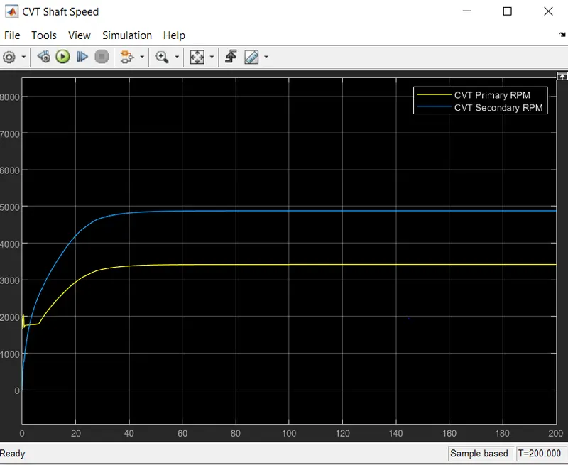
Above image shows the graph of the input and output shafts of the gear transmission system. Values are shown aspect to the gear ratio.
Torque vs Engine Speed 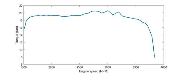
Above image shows the graph plotted between the Torque and the Engine speed.
- Case2: Simulink Model for BAJA ATV CVT with Dashboard
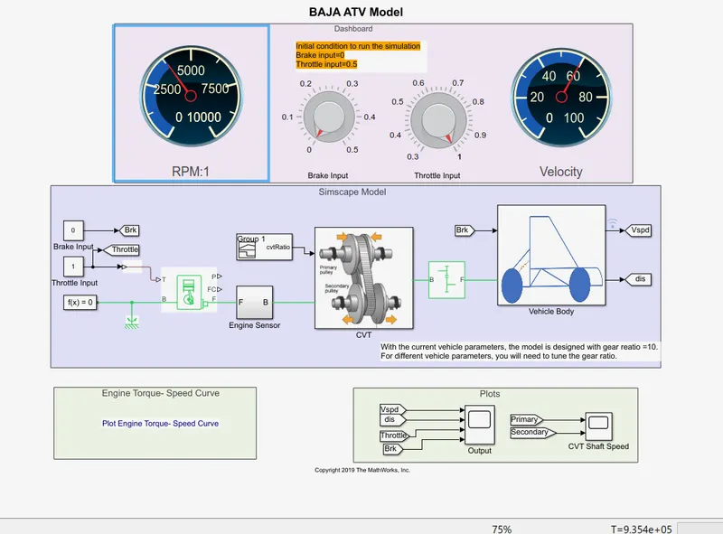
Above Simulink mode described as having a dashboard for the Baja ATV vehicle with the specific knobs for controlling the inputs, As in the case inputs are Throttle and Brake input are not provided with the signal builder.
- Results
Running the model at Brake input = 0.1
Threshold input given is 0.8
Outputs as results by the running the model at the conditions
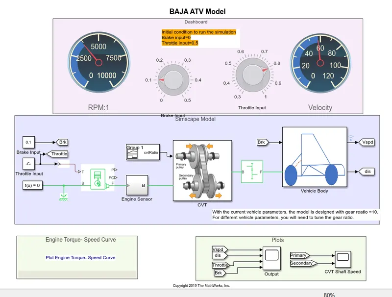
Observed Speed in the model is near 60km/hr predicted speed is 58 km/hr.
Output results can be seen in the graphs plotted
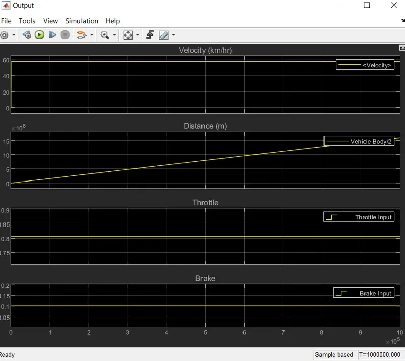
Observations:
Speed = 58km/hr , Throttle = 0.8 Brake=0.1 Time = 1000000 seconds to run the model.
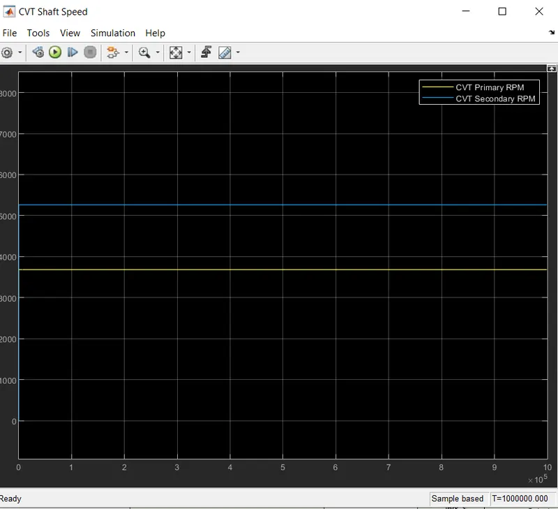
CVT Shaft Rpm Results -
- Case3: Simulink Model for BAJA ATV With CVT using look up table:
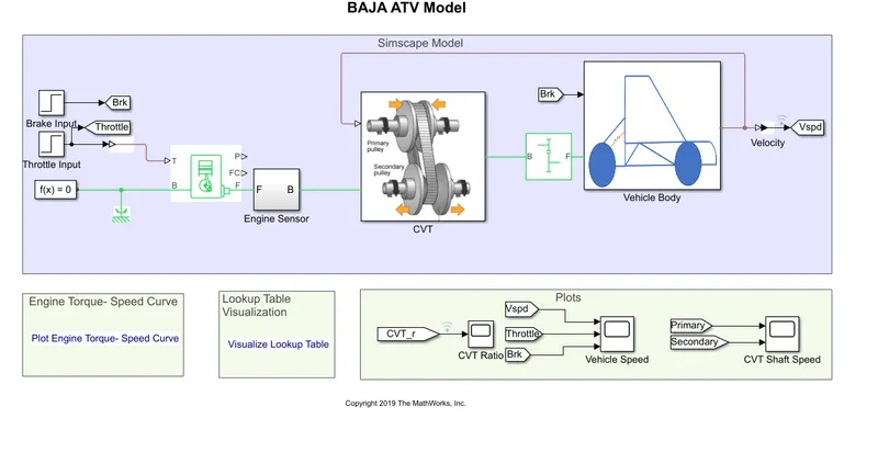
Above image shows the Simulink Model of the BAJA ATV model visualizng Lookup table
- CVT Model Block Diagram:
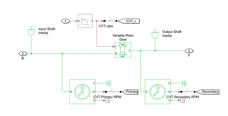
Above image shows the model of the CVT Block , the differnce can be predicted by visualizing the given gear ratio input is provided by using a look table herecomparing to the above cases Case 1 and Case2.
CVT Gear ratio:
Given Lookup Table Visualization:
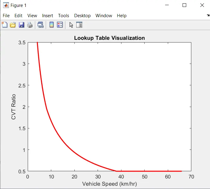
Above image shows the given Lookup table for the Cvt gear Input model
As a plot between the Vehicle speed and the CVT Ratio.
- Results:
Output reults observed on the vehicle :
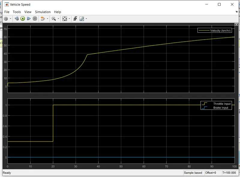
Sample based Time for running the model is 100 seconds.
Also speed is gradually increasing upto 40km/hr and hence increase further.
Throttle input upto 20seconds is 0.3 after 20seconds the Throtlle input becoms 1.
Brake input is 0
CVT SHAFT RPM results :
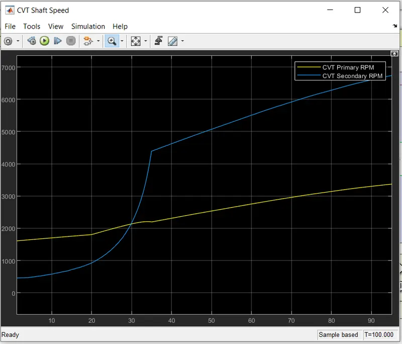
Above image showing the results for the Primary and Secondary CVT Rpm results.
Case 4: BAJA ATV With CVT using look up table with dashboard:
- Simulink Model for BAJA ATV With CVT using look up table with dashboard-
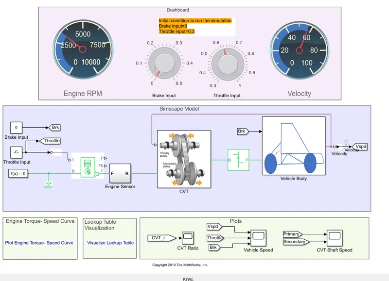
Above image shows the Simulink Model of the BAJA ATV model visualizing Lookup table with Dashboard.
- Simulink Model used for CVT :
Above image shows the Simulink model for the CVT,
- Results:
- Outputs of vehicle Speed-
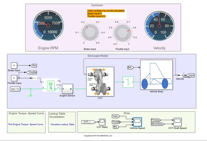
Model representing the data
Observations from the model are: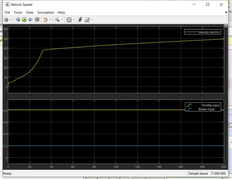
As th e brake input is set to the 0.2and the throttle is set to the 0.8 Engine rpm nearly 26000 also speed of the vehicle is nearly 50km/hr.
Above images shows the output results of Velocity of the vehicle Throttle input Brake input Plotted on the graph. For the sample based time = 200seconds.
CVT Shaft Rpm Results -
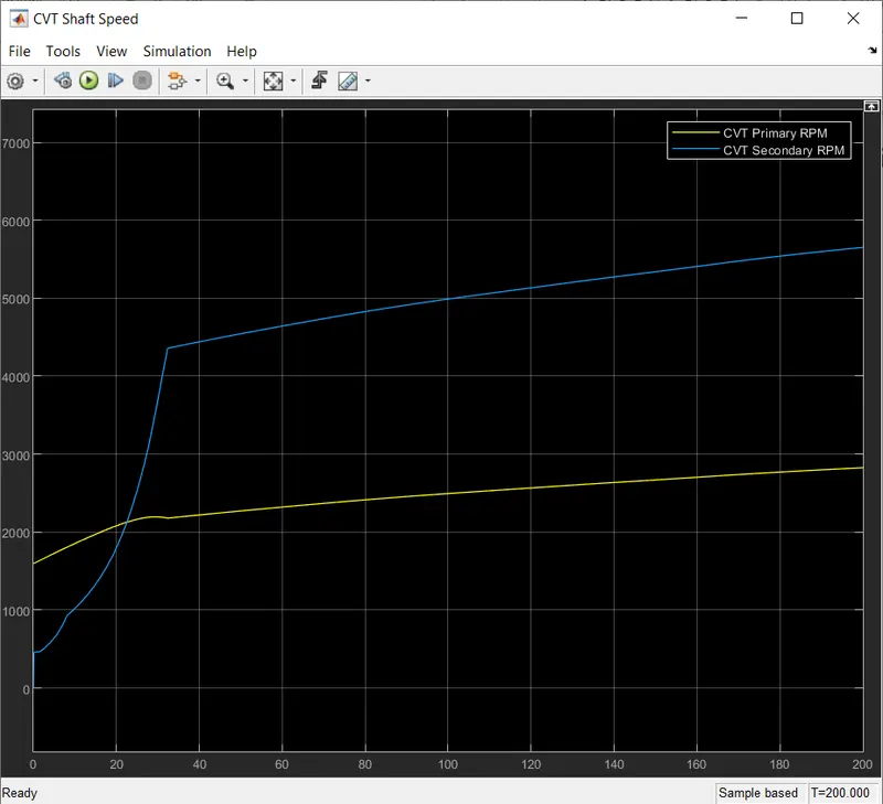
Above image showing the results of the shaft of the Primary and Secondary CVT Rpm.
- Conclusion:
Hence we have made a project Study on the BAJA ALL- TERRAAIN Vehicle (ATV) under different conditions. We have divided the project in 4 Cases
Case1: Simulink Model for BAJA ATV With CVT.
Case2: Simulink Model for BAJA ATV With CVT and with the dashboard.
Case3: BAJA ATV With CVT using look up table.
Case 4: BAJA ATV With CVT using look up table with dashboard.
And recorded the outputs with the above datas